AIRZONE MANTEL RECEIVER

CONTACT : COMMENTS AND QUESTIONS
back/home
In Australia the design and performance of vacuum tube broadcast receivers had reached
a very high standard by the 1940s.
The transmitter powers were relatively low - usually 10KW for the national stations and
2KW for the commercial transmitters. This, coupled with vast distances, dictated very sensitive
receivers.
By 1940 much attention was given to increased fidelity with higher
bandwidths and lower distortion.
Negative feedback and push-pull amplifiers were introduced into the audio stages.
The bandwidth of the IF amplifier was "ganged" with the tone control to give a full
audio bandwidth of 5KHz.
Two manufacturers producing such designs were Breviille and Airzone.
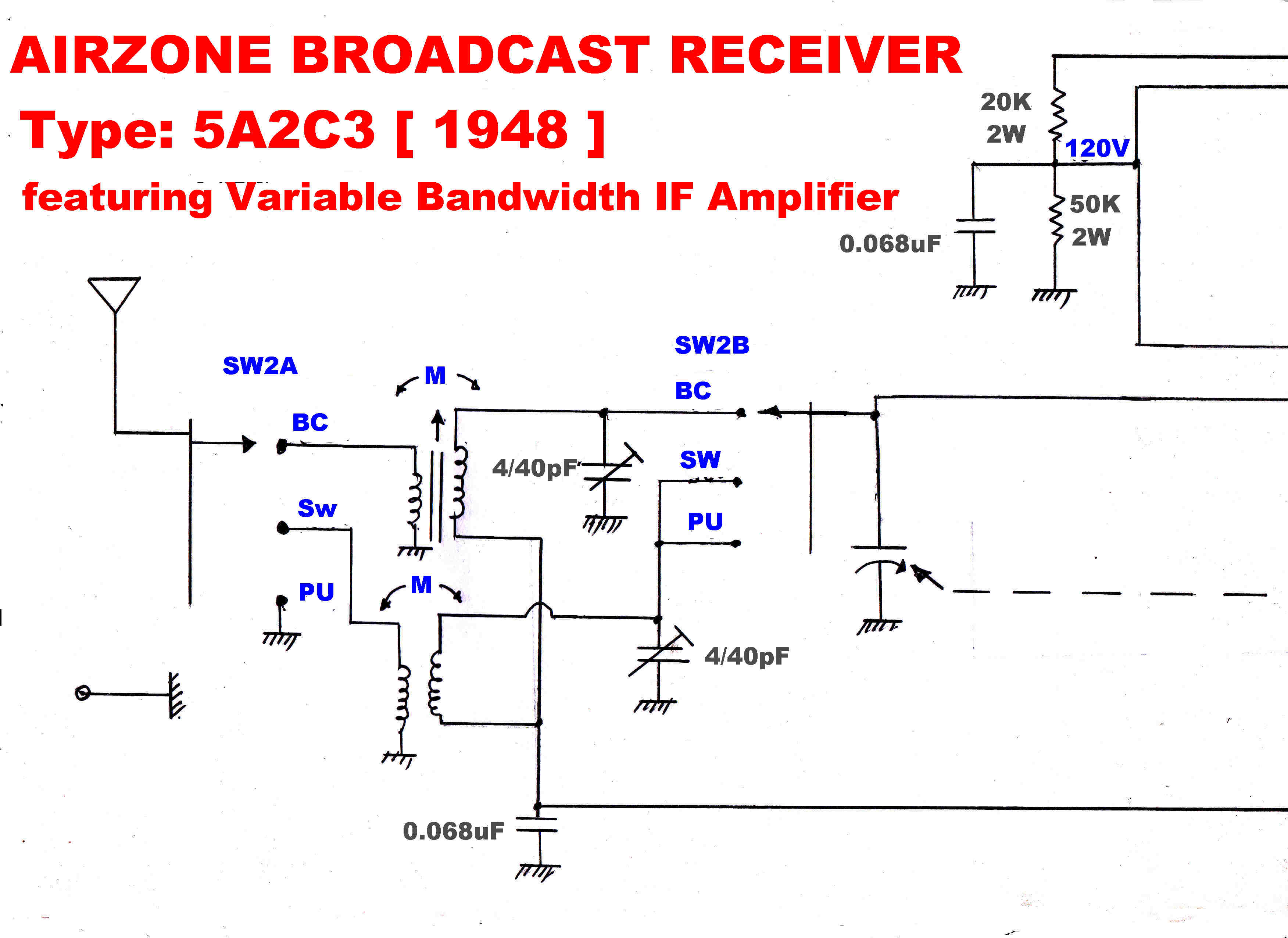
The following section is a discussion of the design and performance of an Airzone mantel receiver
type 5A2C3.
Some of the points mentioned here are discussed in more detail in the Tuner and Regenerative
Receiver section.
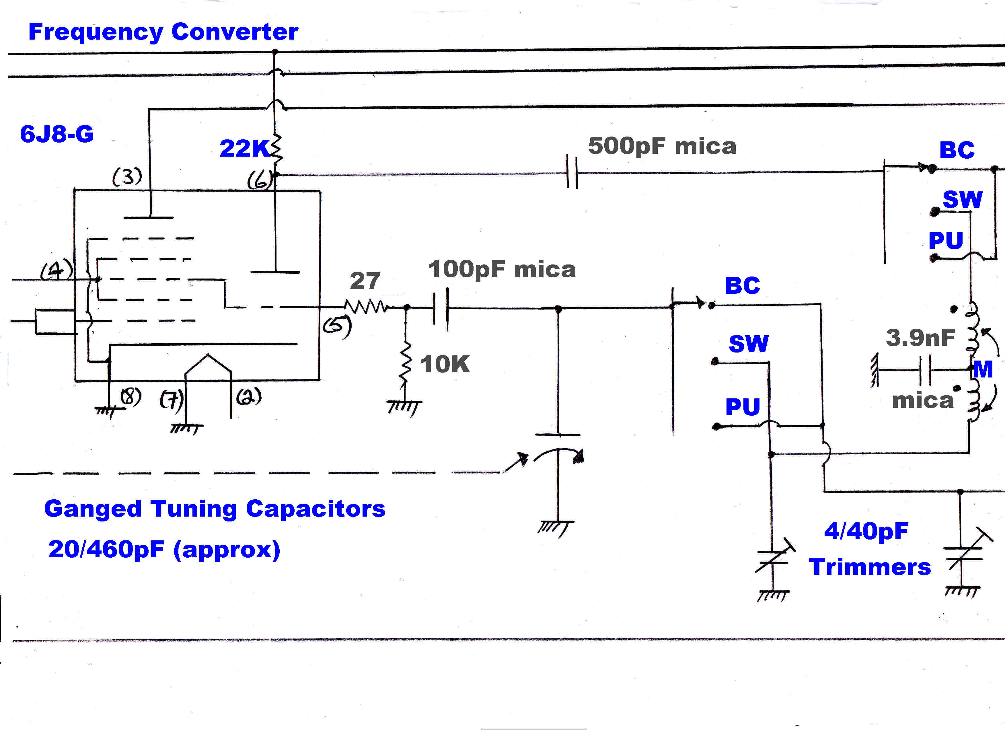
The circuit of the Airzone mantel broadcast receiver is shown below.
|
|
|
|
|
|
RECEIVER BANDWIDTH
In the thirties and forties the de facto standard for the upper cut off frequency for AM audio
broadcasting was 5KHz.
Many of the transmitters had a useful response to at least 15KHz.
We have a record of this from Bode plots on the transmitters that sometimes extended out to 100KHz.
These were used to design stabilizing networks for envelope feedback. This consisted of a high
level diode detector coupled into the final tank circuit, providing an overall feedback signal into
the low level stages of the modulator.
A power rectifier such as the 5AR4 with carrier input of about 400 volts
was used as the detector. Under such conditions the detector distortion is extremely low.
To limit co-channel interference at night a 10KHz low pass filter was inserted at the input
to the modulator of the transmitter. Since the channel spacing in the capital cities was at least 100KHz,
these could be removed in daylight hours to give a full frequency range.
When received on a wide band low distortion tuner, direct studio broadcasts achieved a quality more
than competitive with any other system.
However most signals were limited to a bandwidth of 5KHz before they reached the transmitter.
There were two reasons for this:-
The main disc pickup used by the ABC during this period was the Western Electric WE4A.
This was designed as a second order system with a cutoff frequency of 5KHz.
Virtually all recorded music broadcast had a cutoff of 5KHz.
Many of the programs arrived over open wire transmission lines, either between cities, or
to regional transmitters. For channeling purposes, the signals in such transmission systems
usually encountered a number of very sharp cutoff low pass filters - usually with a 5KHz. bandwidth.
By the mid thirties broadcast receiver design had stabilized and used one IF stage
with two mutually coupled IF transformers on 455 - 465 KHz.
In order to extract maximum selectivity, these were usually under-coupled to give a very droopy
baseband response with a typical 3 db frequency of about 2.5 KHz.
The audio was not very bright, but acceptable.
Expressed in more modern terms, the baseband transfer function contained four poles close to the real
axis to give an approximation to a Gaussian response.
At least two Australian manufacturers elected to produce broadcast receivers flat to 5KHz.
- the Breville 239 and the Airzone 5A2C3.
Both receivers reflect the excellent design standard Australian receivers reached.
This article describes the techniques used in the Airzone to produce a broadband IF which can
be switched to the more selective response if required.

A plot of the baseband response of the Airzone in the normal and wide band position
is shown above.
The 3db point in the normal position is 2.5KHz. The receiver is 3.5db down at 5KHz.
in the wide band position - a remarkable result after sixty years of operation.
The step function response is also sketched in.
This is consistent with the steady state response.
The "droopy" response in the narrowband position produces a monotonic output with a slow rise time.
The broadband response with a greater bandwidth and sharper cutoff produces a shorter rise
time with overshoot.
The broadband IF is always in circuit when the receiver is on the short wave band.
This is almost certainly to accommodate frequency drift in the local oscillator.
Acoustic feedback in vacuum tube short wave receivers caused problems - particularly on the
upper end of the short wave band. Broadbanding the IF reduced the problem.
This is discussed in the tuner section.
A number of conditions should be met in broadbanding an IF amplifier:-
(1) The centre frequency, and so the receiver alignment, should not
change as the bandwidth is increased.
(2) Any switching should be at a low impedance level to avoid stray
capacitive coupling which will either modify the pass band or,
at worst, produce instability.
Increasing the mutual coupling between windings increases the bandwidth and leaves the
centre frequency unaltered.
One set of poles moves up in frequency and the other set down by
an equal amount, thus preserving the symmetry about the carrier, but increasing the bandwidth.
Unfortunately, changing the mutual inductance involves changing the relative position of two coils.
This is not easy to arrange in a receiver for domestic use.
Changing any type of capacity coupling always produces a change in the centre of the pass band,
and so detunes the receiver.
If the C of top coupling is increased, the frequency of one set of poles remains fixed while
the frequency of the other set decreases, lowering the centre frequency. The opposite happens with
bottom coupling.
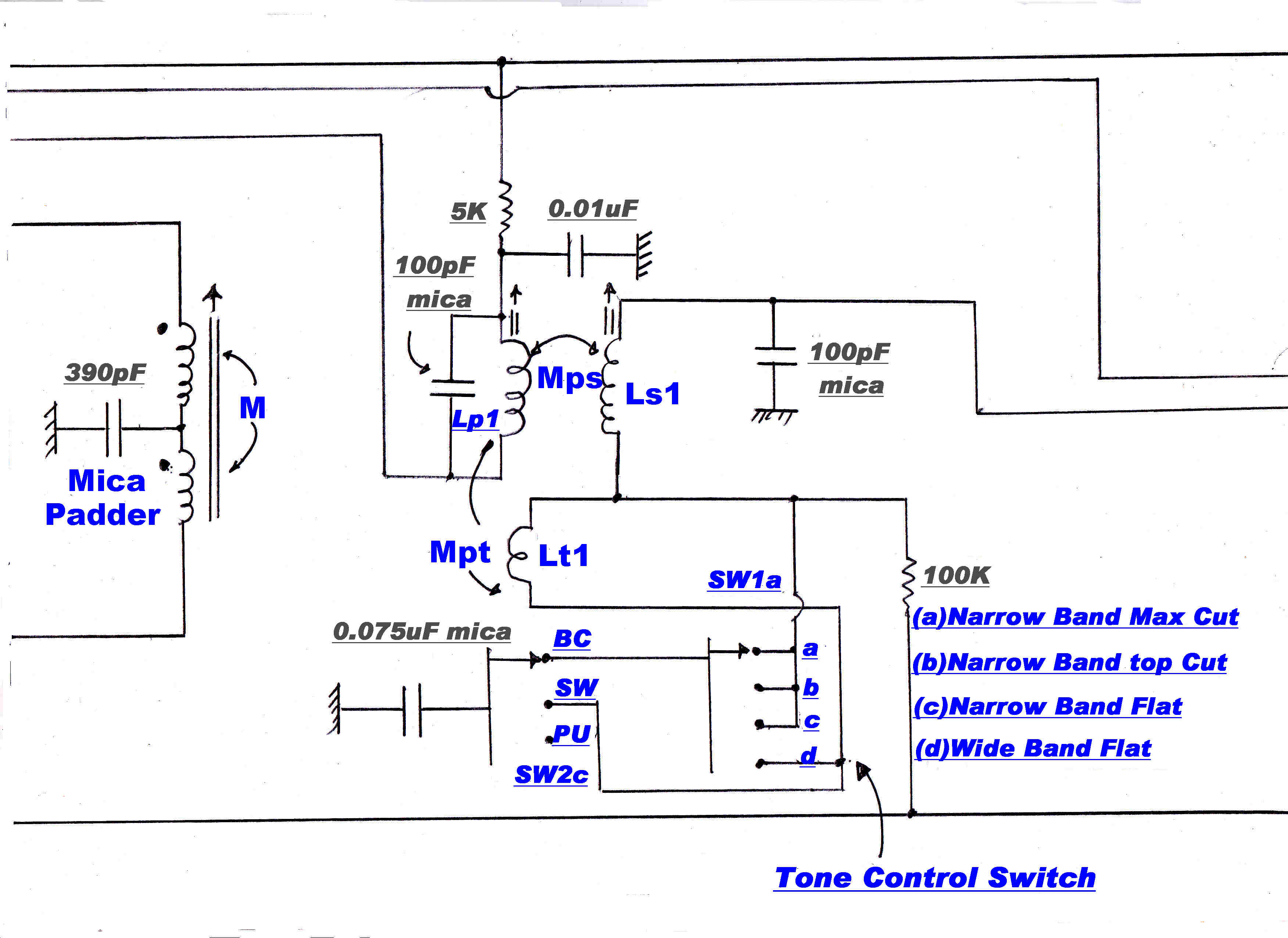
The change of mutual inductance can be closely approximated by a very neat system that involves
only a single switch operating at a low impedance level at the "earthy" end of a transformer.
This is the system used in the Airzone and the Breville.
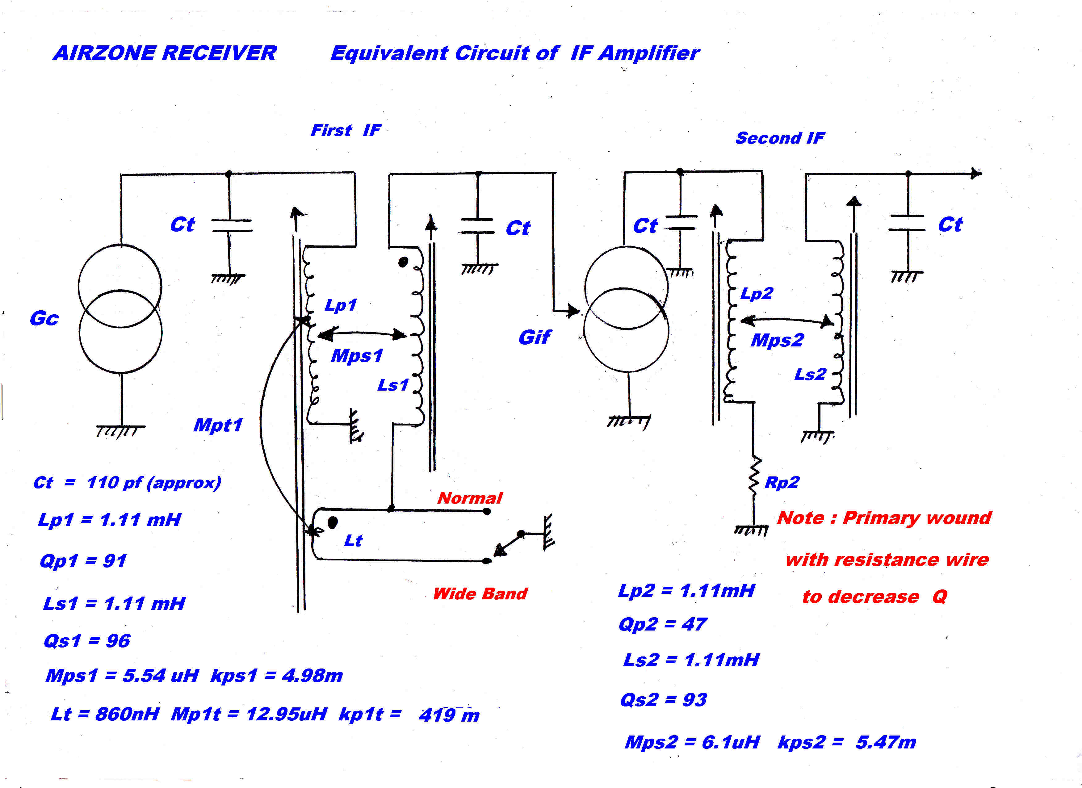
The equivalent circuit is shown above.
To increase the mutual inductance between the primary and secondary inductance, a small tertiary
winding is placed in series with the secondary.
This tertiary winding is closely coupled with the primary, so that its mutual inductance adds to
the primary - secondary mutual inductance.
The inductance of the tertiary winding adds to the secondary inductance, and so will lower its
resonant frequency. The inductance of the tertiary winding should therefore be as low a possible.
To provide a given increase in mutual inductance, therefore, the coupling between primary and tertiary
should be a tight as possible.
Since the primary winding is at HT potential and the tertiary earthed,
insulation requirements mitigate against tight coupling.
It is interesting to see how the designer of the Airzone managed:-
Inductance of tertiary winding = 0.86uH
Coupling factor with primary = 0.419
Increase in Mutual Inductance = 12.95uH
Primary - secondary mutual inductance = 6.1uH (normal)
The secondary inductance is 1.11 mH.
Adding 0.86uH to it detunes it by 176 Hz.
- a negligible amount.
The measured parameters for both transformers are given in the equivalent circuit.
These values are taken with the coils in the cans.
These lower the Qs, the winding inductance and the mutual inductance.
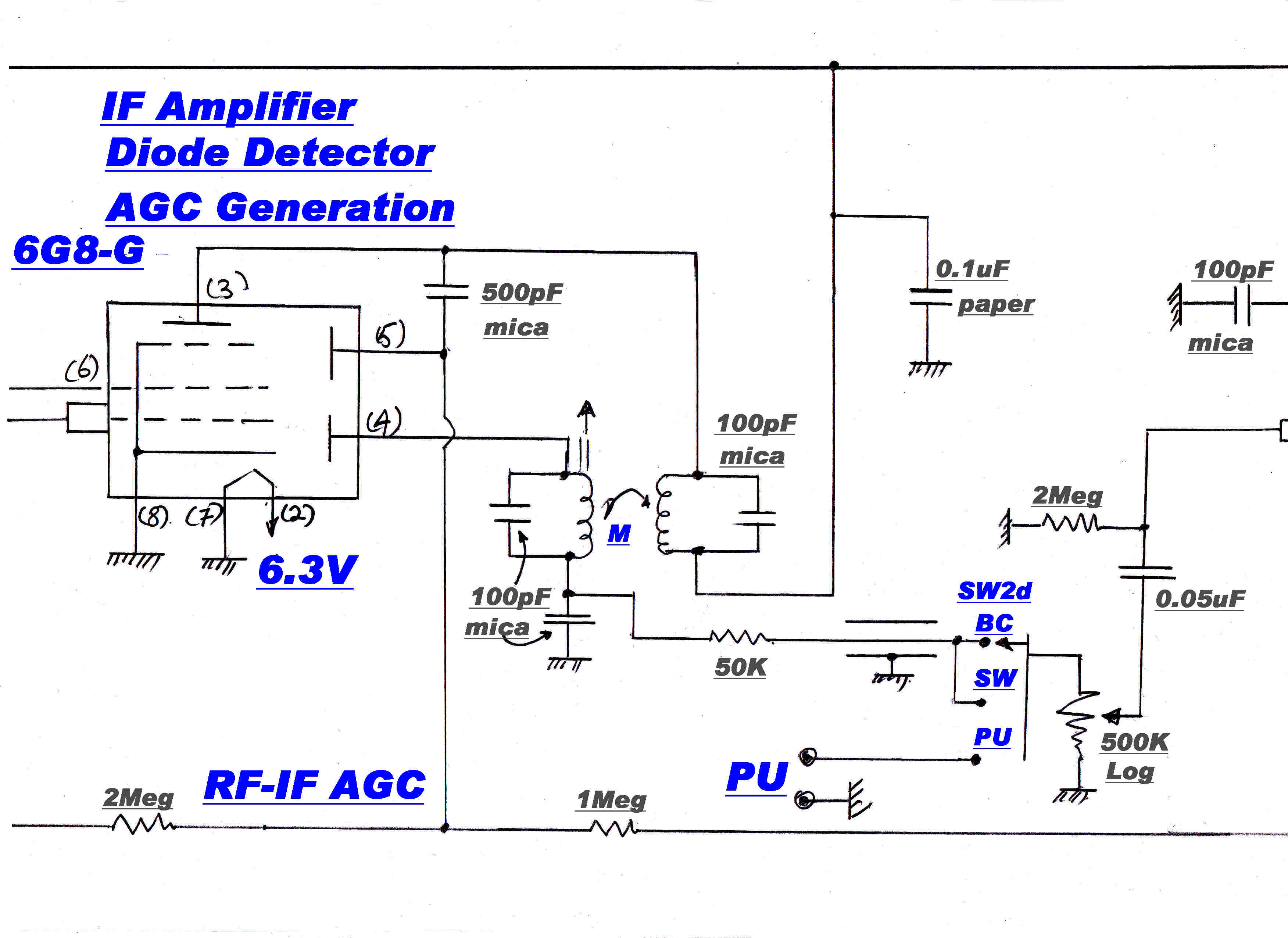
Note that the primary of the second IF transformer is wound with resistance wire to lower
the Q and increase the bandwidth.
The diode detectors provide further loading and increased bandwidth.
In the wide band position the poles of the first transformer are displaced from the real axis.
These combine with a pole on the real axis of the second transformer to give a good approximation to
a maximally flat response.
A picture of the IF transformers is given above.
The 100pf mica tuning capacitors can be clearly seen. In practice about 10pf is added by
tube and stray capacity.
The tertiary winding at the bottom of the primary is also evident.
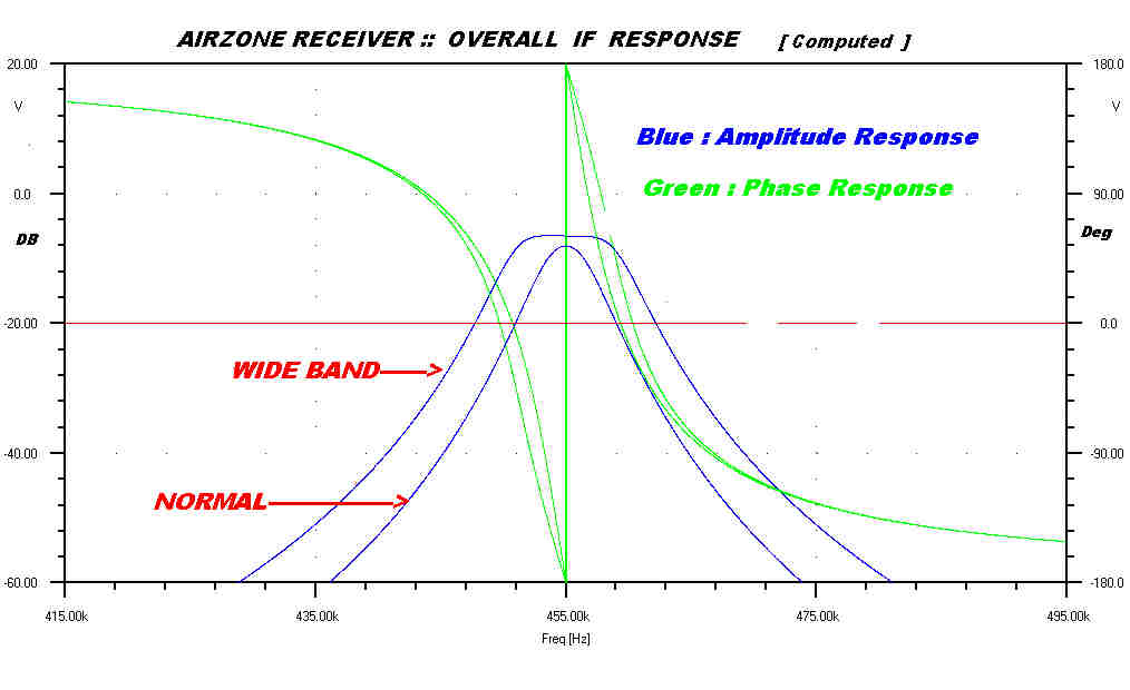
A computer solution for the normal and wideband overall response is shown above.
Note that the Airzone designer has produced a beautiful flat topped response
in the wide band position - not bad for 1948 when only slide rules and log tables were available.
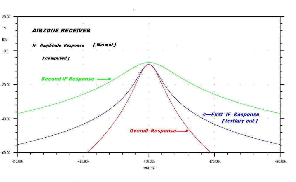
The above computer solution shows how the narrowband overall response is generated by combining the first and second IF responses.
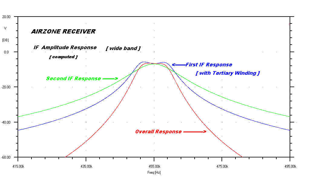
The above computer solution shows how the wideband overall response is generated by combining the first and second IF responses.
Stray capacity coupling between the primary and secondary of vacuum tube IF amplifiers can
have a disastrous effect on the gain and bandwidth.
The coupling coefficient of IF transformers in the normal position is about 5 in 1000.
For top capacity coupling this represents a C of only 0.55pf !
The overall effect will depend on whether the capacity coupling adds or subtracts from the mutual
inductance coupling.
In general, a negative mutual inductance adds to stray capacity coupling and positive coupling
subtracts.
Reversing the polarity of vacuum tube IF transformers can be disastrous if there is any capacity
between primary and secondary.
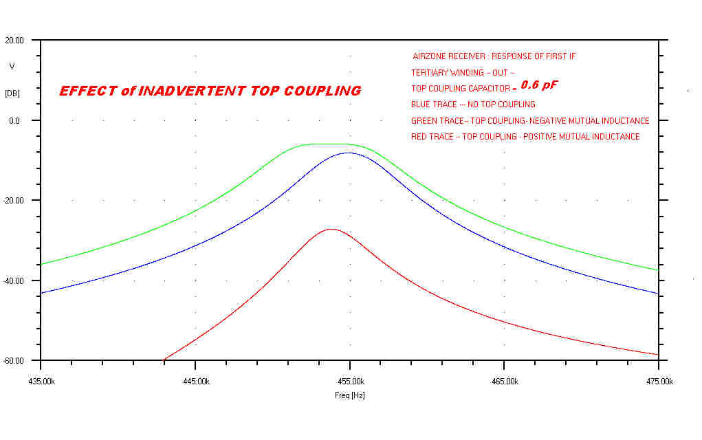
A computer simulation of the response of the first IF in the Airzone in the narrowband position
with a stray capacity of 0.6pf is shown above.
With positive mutual inductance the bandwidth and gain are drastically reduced. With negative mutual
inductance the gain and bandwidth are increased, but the IF is detuned with its centre lowered by
approximately 2KHz.
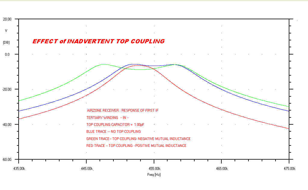
A computer simulation of the response of the first IF in the Airzone in the wideband position
with a stray capacity of 0.6pf is shown above.
If both windings of a transformer are wound in the same direction, negative mutual inductance
occurs when the input and output are taken from the bottom and top or, alternatively, both are taken
from the centre
In order to reduce the input to output capacitive coupling to a very small value, vacuum tubes
were designed with the grid brought out to the top of the tube. The drastic effects of only small
coupling illustrate its importance.
There are two main sources of distortion in the RF - IF amplifiers
of AM broadcast receivers:-
(1) The curvature of the plate current - grid voltage characteristic of the IF
output stage [ 6G8]
(2) The diode audio and AGC detectors.
Diode detectors are one of the few circuit elements where the distortion decreases as the signal
level increases.
The opposite is true of the IF output stage. The design then involves a compromise.
It can be shown that no distortion occurs to the modulation on an AM wave when passing through
a device with a square law transfer characteristic.
This means that the IF amplifier tube will produce no distortion if:-
Ip = K [ Vco + Vg ]^[ 2 ]
Where Ip is the plate current.
Vco is the grid cutoff voltage.
Vg the grid voltage.
If we differentiate, we see that, for no distortion in the output stage of the IF amplifier,
the Gm should rise linearly with grid voltage:-
dIp/dt = Gm = 2K [ Vco + Vg ]
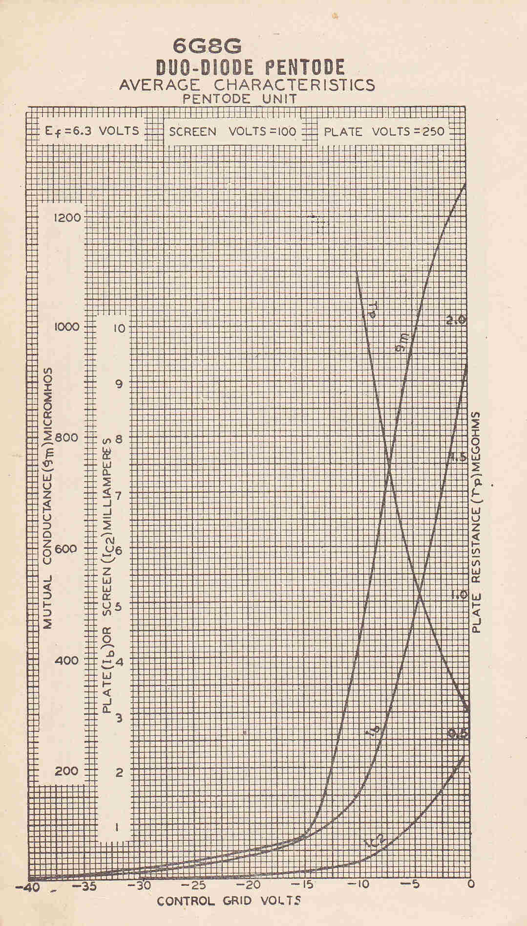 A plot of the Gm of the 6G8 against grid voltage is shown on the right.
For most of the working range the ideal characteristic given above is closely approximated.
The 6G8 provides an IF output stage with low distortion.
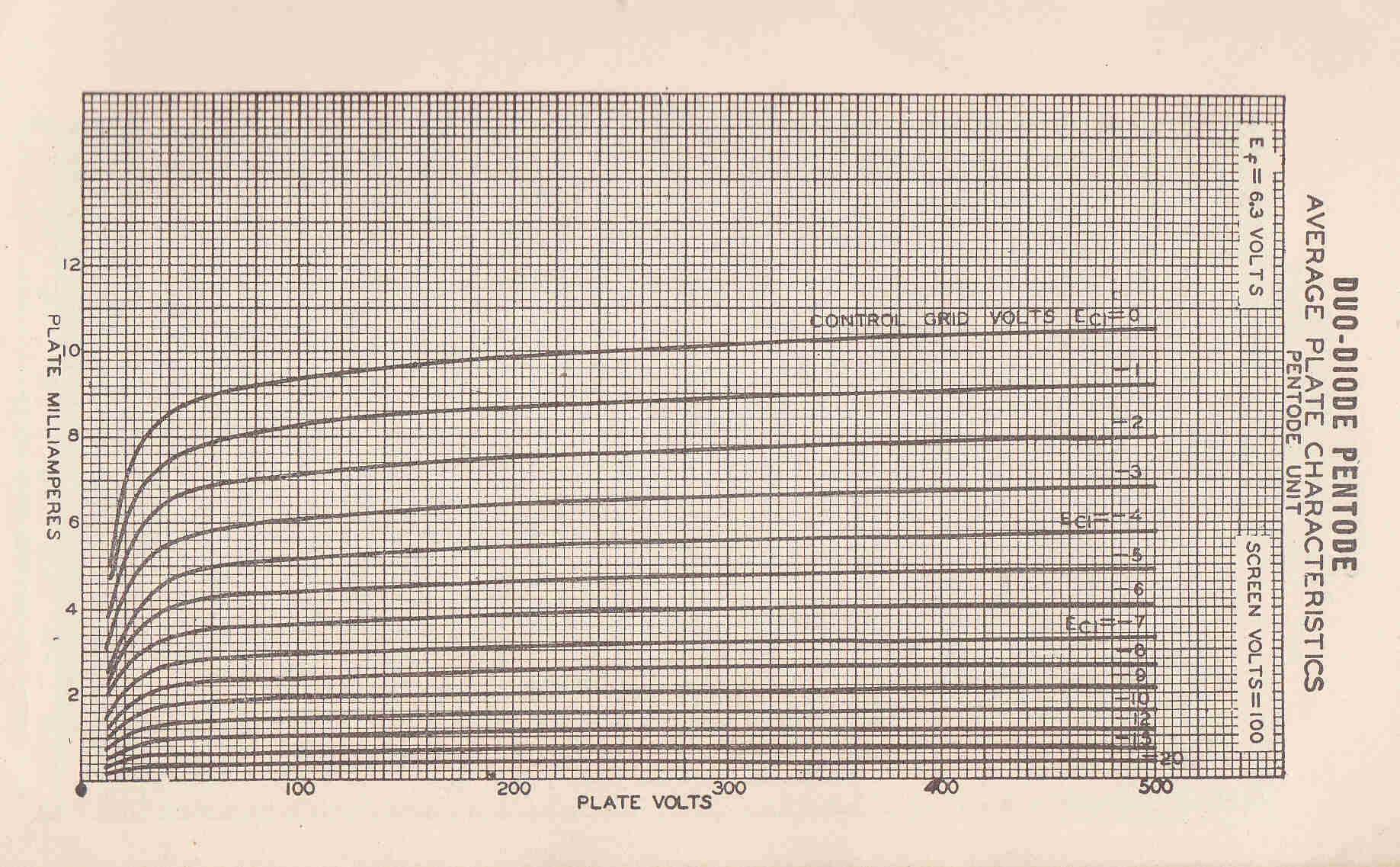
The plate current curves for the pentode section of the 6G8 are shown above.
At a grid bias of -2 volts the plate resistance is about 570Kohms.
It increases with increasing grid bias, and so has little effect on the Q of the tuned
circuit in the plate.
The variation of input capacity with bias can be more of a problem when the
RF/IF transfer function is critical.
The increase in input capacity from cold to maximum plate current is usually about a third
of the cold capacity.
To minimise the effect either:-
(A) A small non-bypassed resistor can be included in the cathode.
or
(B) The tuning capacities can be inceased or the input tapped down in a capacitive divider.
In a few high quality Australian receivers with RF stages, such as the Breville 239 [1940],
no AGC was applied to the IF stage.
Note: The circuit of the Breville 239 with an analysis is given in the HISTORY SECTION under the title:-
AM RECEIVER QUALITY VERSUS TRANSMITTER PERFORMANCE
The IF stage was operated under fixed bias conditions to give minimum distortion.
The AGC applied to the RF and mixer stages gave adequate gain control.
As far as I know, the 6G8 was an Australian designed tube produced by AWA in Sydney.
Once again, Australian design was of a high standard.
The plate current of the 6G8 IF stage does, however, carry an audio component with
some distortion. The square law transfer characteristic gives rise to what was called
"anode - bend detection".
This was of importance in some Australian receivers which were "reflexed".
In these receivers a second IF stage was added. The IF output tube was also used as the audio
voltage amplifier driving the power output pentode.
The demodulated component in the IF stage passed directly to the grid of the output, bypassing
the volume control. When this was turned to the "off" position low level distorted audio remained.
The modulation depth which a diode detector can handle increases as the ratio of
the total AC to DC load increases.
Typically, in many receivers a DC detector load of about 500k was coupled into a 1Meg
volume control pot. with a 0.02uF condenser. This severely limited the maximum modulation depth
without clipping.
In the AIRZONE the 500k volume control pot. provides the diode detector load. Under normal
listening conditions the 2Meg AC load of the audio input stage is set towards the bottom of the pot,
so the AIRZONE can handle modulation depths well above 95%.
The diode detector generating the AGC voltage is a further cause of distortion. The AGC detector
is biased off with a back bias of about -3volts, so that no AGC is produced until the carrier reaches
a preset value. Under test conditions, with a fixed depth of modulation,
this presents no problem. With dynamic modulation, a nonlinear
load is presented to the IF amplifier and distortion can result. The effect is not easy to quantify.
When tuning between stations large changes in signal level can occur. For a fast recovery,
low time constants around the AGC loop are desirable. Fast response is also required for short wave
reception.
If the response of the AGC system is made too fast it will mistake the low frequency modulation
component as a change in signal level and try to suppress it. Unfortunately this process is highly
non-linear and can cause fierce distortion on high-level low frequency amplitude modulation.
The AIRZONE is a mantel model and so the low frequency response is limited and the effect was not
detectable. It can be serious in large cabinet receivers with a better low frequency response.
In high quality wideband low distortion AM tuners two AGC time constants should be provided -
a low one for tuning and a very long one for normal operation. This is possible because of the
stability of ground wave propagation on the broadcast band.
When an amplitude modulated wave passes through any network it splits into two - an in-phase
carrier and a carrier in phase quadrature.
The modulation on the two new carriers is not the same as the original modulation,
but is related to it by two linear differential equations.
Because these equations are linear there is no distortion on the modulation of either wave.
However, diode detectors respond to the envelope or amplitude of the wave. The amplitude of two
waves when 90 degrees out of phase is obtained by squaring the amplitude of each, adding them, and
then taking the square root. This is a non-linear process, so a diode detector will always produce
distortion when a quadrature wave is present.
Any asymmetry about the carrier frequency, either in amplitude or phase, will generate a quadrature
wave.
Most asymmetry in receivers is caused by mistuning or misalignment. Since the parameters of the
Airzone IF are known, it is interesting to do a computer analysis to find the irreducible minimum for
a perfectly tuned receiver.
QUADRATURE DISTORTION
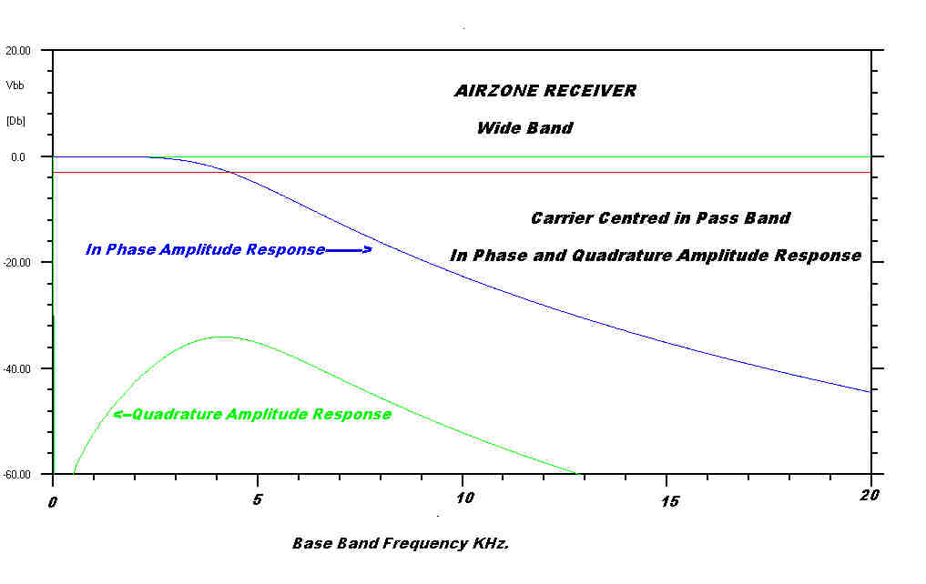
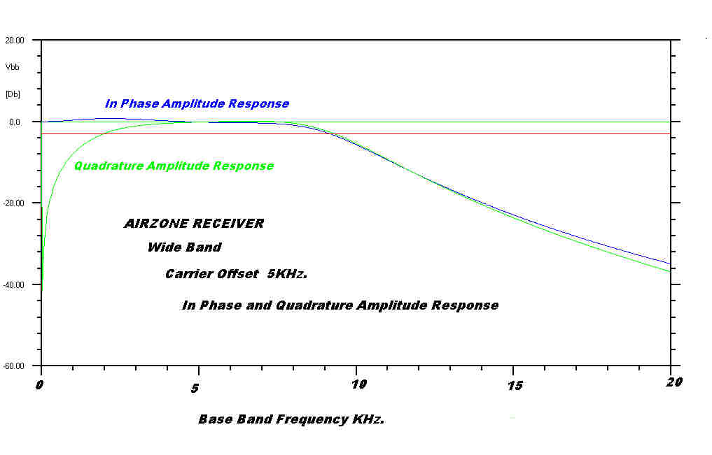
The plot of the I and Q components is shown below.
|
|
|
Receiver Centered in Pass Band |
Receiver Detuned by 5KHz. |
TRANSIENT RESPONSE
The step function response corresponding to the tuning conditions shown above.
|
|
|
|
Receiver Centered in Pass Band |
Receiver Detuned by 5KHz. |
QUADRATURE DISTORTION of SINUSOIDAL MODULATION
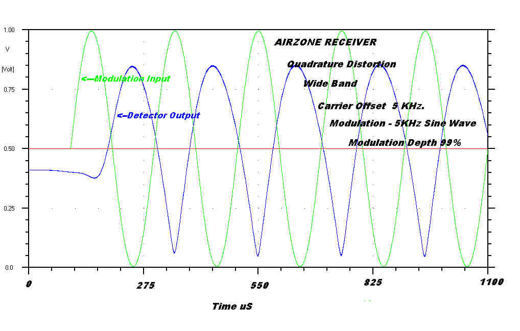
The distortion on a 5KHz. modulated wave with the receiver detuned by 5KHz. is shown above.
The generation of a quadrature carrier explains the distortion when receivers are mistuned:
and also the distortion on skywave at night when ionosphere transmission
develops severe asymmetry.
The output from a product demodulator is either the IP or Q component or a linear combination
of both. No distortion can occur in an AM transmission link with a product demodulator.
This is one of the great strengths of AM transmission.
On the other hand, FM modulation is governed by a nonlinear differential equation
and distortion always occurs. With FM the trick is to design a transmission network
to reduce the distortion to an acceptable amount.
Unfortunately, as with multipath caused by reflection, the response of the transmission path
is not always under the control of the design engineer.
It can be shown that distortion to an FM wave is always accompanied by incidental
amplitude modulation.
The above serves as a pointer in the design of very high quality tuners.
AM broadcast tuners should employ both envelope and product detectors. The envelope detectors
are used for house keeping duties such as AGC and during tuning, with the product detector providing
the long term audio output. This technique is adopted in the high fidelity tuner described
in another section.
FM tuners should have a front end with an AM detector, so that an estimate can be made of the
distortion occurring over the transmission path. As pointed out in the introduction, FM network
distortion is always accompanied by AM.
It is highly desirable that the local oscillator amplitude be constant across the band,
since there is an optimum injection level into the grid of the mixer.
Too low an injection level reduces conversion transconductance and increases conversion noise.
Too high an injection level again reduces conversion transconductance and increases
cross modulation.
Fortunately, the optimum injection level is fairly broad.
To achieve a constant amplitude across the broadcast tuning band, two separate
feedback paths have been designed into the Airzone oscillator.
At high frequencies, mutual inductance coupling predominates. The padder capacity and the
variable tuning capacity form a capacity voltage divider which provides positive feedback at the
low frequency end to give a Colpitts oscillator.
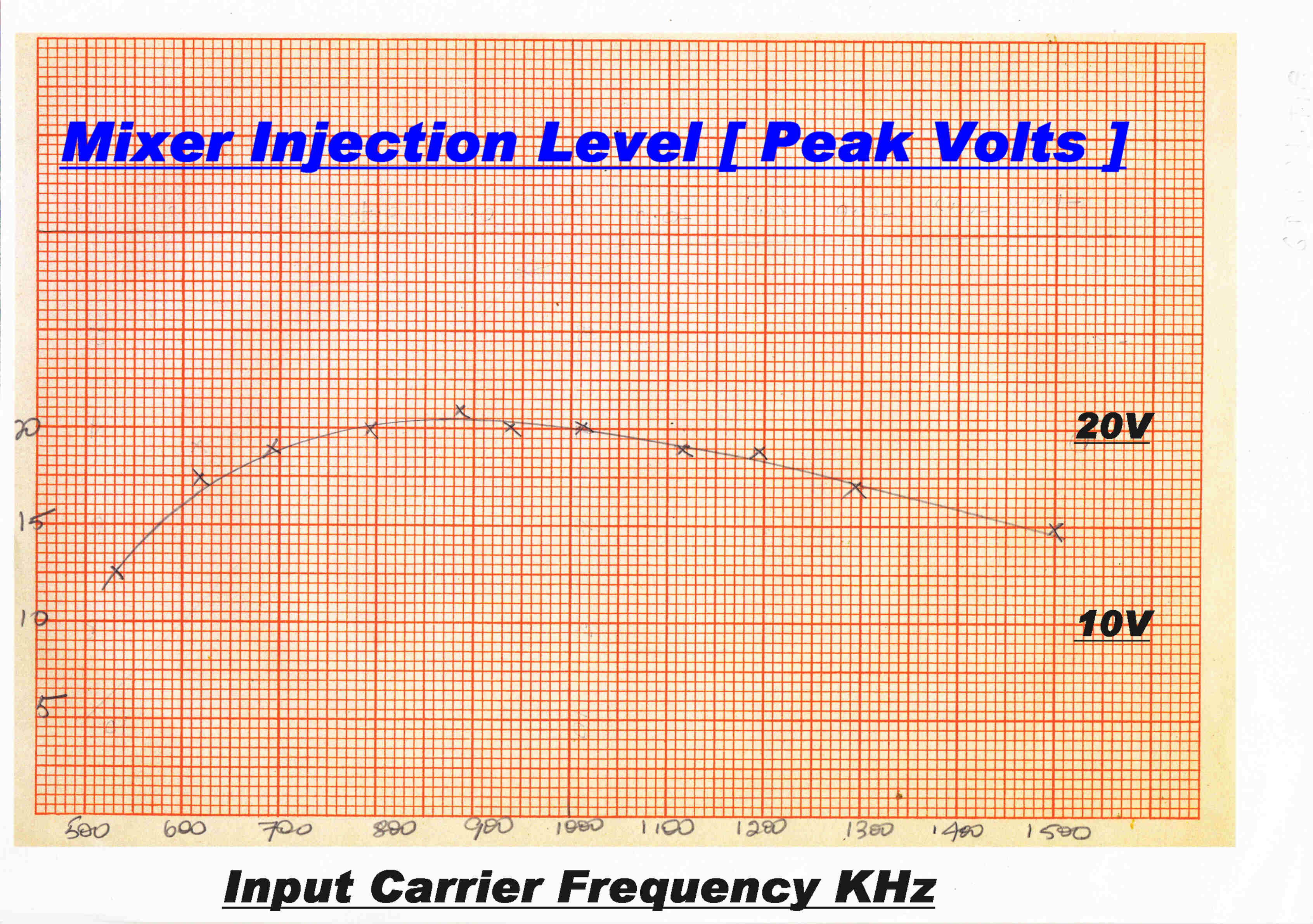
The variation of local oscilltor amplitude across the band is shown above
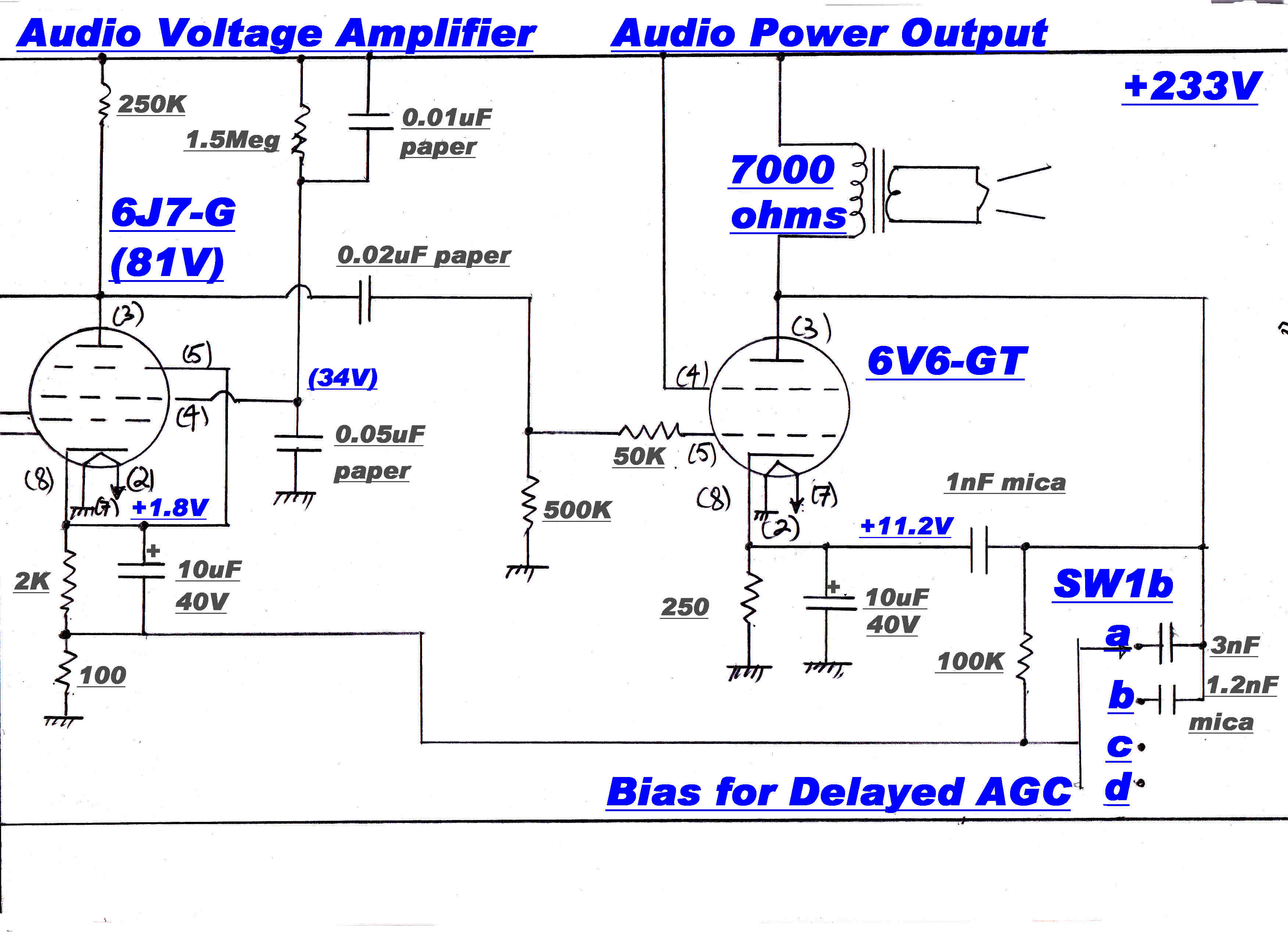
The audio amplifier follows the usual topology of a pentode voltage amplifier driving a
single ended pentode output stage.
However, there are a number of refinements not found in the usual mantel receiver :-
(1) Negative feedback is applied over the audio amplifier.
"Tone Control" or high frequency attenuation is achieved by varying the amount
of high frequency feedback. This control is also ganged to alter the IF bandwidth.
The main stabilising pole in the forward loop is formed by the 100pF capacitor in
the plate of the 6J7 pentode voltage amplifier.
(2) The capacitive voltage divider ( 0.01uF and 0.05uF ) in the screen of the 6J7
provides feed forward to cancel high tension disturbances in the plate.
This technique is discussed fully in the 6V6 amplifier section.
A back view of the receiver is shown below:
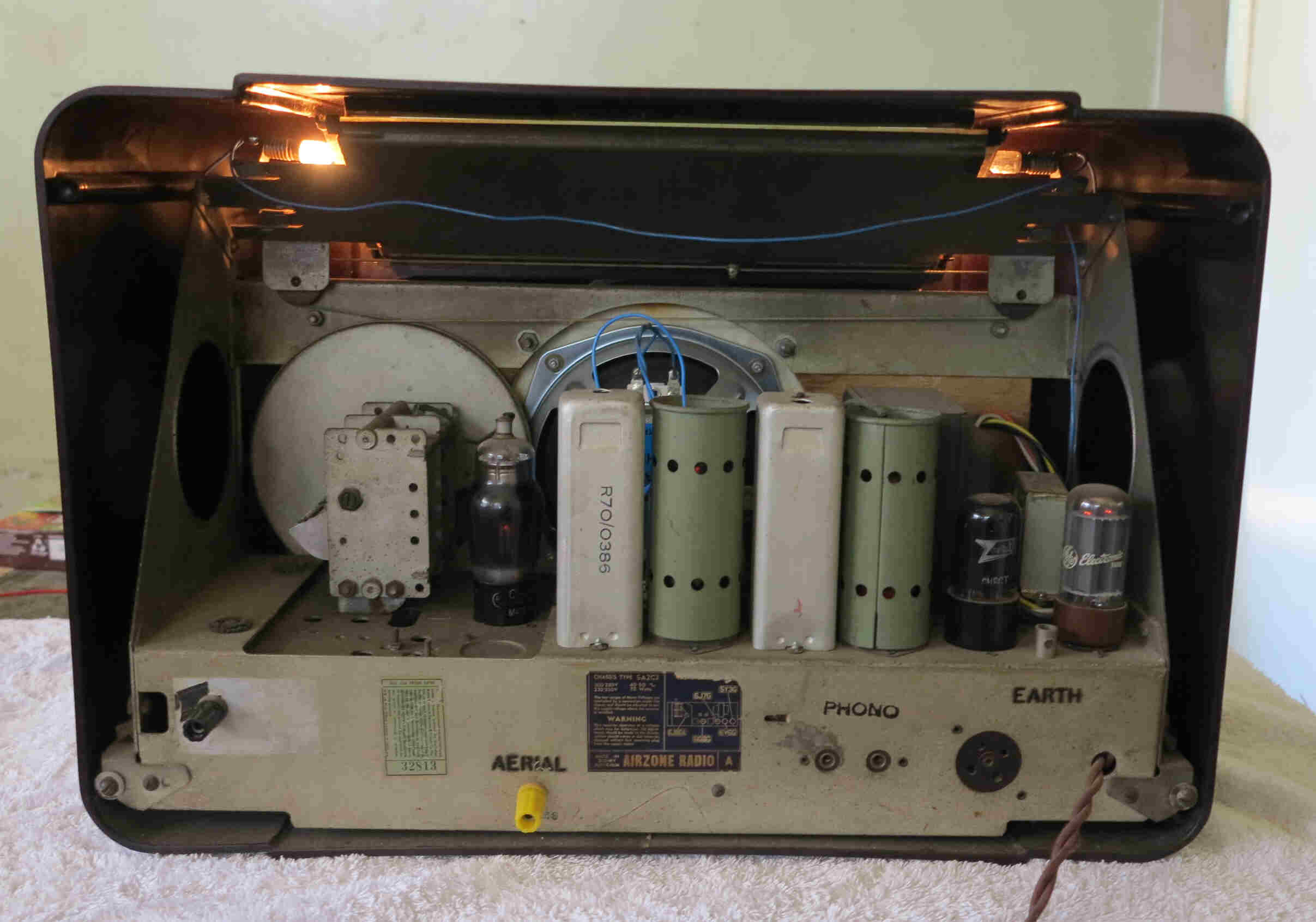
The signal progresses from the tuner on the left to the 6V6 output on the right.
The 6V6 is followed by the 5Y3 rectifier.
Note that the tuner has a spare place for an RF amplifier and extra gang on the
tuning capacitor.
The heavy shielding on the 6G8 and the 6J7 is also noteworthy.
Very few mantel receivers were equipped with short wave.
This was due to acoustic feedback.
In mantel receivers the speaker was in close proximity to the converter stage.
Vibration of components in the local oscillator ( triode valve, tuning capacitor,
tuning inductor and wiring ) caused frequency modulation.
This was demodulated when the receiver was tuned through the flank on the IF
and completed a mechanical feedback loop.
The problem was particularly severe on the top end of the shortwave band.
Note that the tuner subassembly in the Airzone is mechanically isolated with
rubber mounts to minimise the coupling.
|
|
|
|
|
|
|
|
|
|
|
|
|
|
|