|
It would seem the practice these days to denigrate
the AM service on the broadcast band. In fact,the medium wave
AM service can probably cover a greater service area with better average fidelity
than any other broadcast system. This is particularly valuable in Australia where
large sparsely populated areas must be covered.
The wheel is old technology, but it is still used because it is
highly appropriate for the task: and so for amplitude modulation on the
broadcast band.
This introduction is devoted to AM techniques: the design of an ultra
low distortion wide band AM tuner and low power transmitter,
and then a discussion of the distortion mechanisms
in both AM and FM transmission.
INDEX
The Tuner is all solid state and looks like this:-
GENERAL DESCRIPTION:-
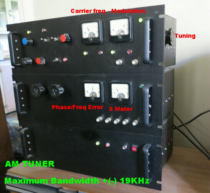 The maximum bandwidth of the tuner is +(-)19KHz.
This can be reduced to +(-)8KHz or +(-)5KHz.
Two additional IF strips can be added in series:-
(a)A fifth order maximally flat filter +(-)15KHz.
(b)A sharp ceramic filter +(-)8KHz.
The IF frequency is 455KHz.
(c) A variable depth 9KHz. notch filter may be inserted in the audio path.
The tuner is equipped with four demodulators:-
(a)An ultra low distortion envelope detector which can handle
100% modulation.
(b) Two product demodulators for the I and Q components.
(c) The phase modulation on the carrier is extracted from the error
in the phase lock loop with a sensitivity of 1 volt per 5 degrees.
Low frequency phase modulation is caused by non-linear processes
in the transmitter. High frequency phase modulation is usually
due to an assymetric pass band in the matching hut and radiating system.
The AGC loop contains an integrator, so that the DC gain exceeds 106.
Consequently the output from the detectors is a function only of the modulation
depth and independent of the input signal level. This facilitates the
calibration of modulation meters and modulation alarms.
All outputs including the IF signal are available simultaneously.
Modulation is presented on a meter in three modes:-
(a) Average modulation.
(b) Positive peak sample and hold.
(c) Negative peak sample and hold.
Red and green leds indicate modulation greater than 95% in either
the negative or positive direction.
With present day practice these lights remain on almost continuously.
Sample audio is included.
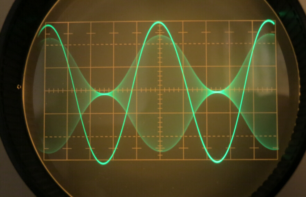
TUNER TRANSIENT RESPONSE
BANDWIDTH = +(-)19 KHz.
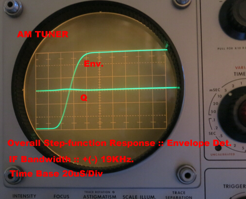 In the 19KHz. bandwidth position the slope of
the amplitude response flanks is not very steep, so that the
transient response is essentially monotonic with a rise time of
about 22uS.
In the 19KHz. bandwidth position the slope of
the amplitude response flanks is not very steep, so that the
transient response is essentially monotonic with a rise time of
about 22uS.
The response is not completely symmetrical about the carrier
resulting in a small output from the quadrature detector.
In daylight hours the tuner is operated with a bandwidth of 19KHz.
It was expected that the resulting increase in noise would be intolerable
in a suburban location. This is not the case, so that it should be possible
to use the full audio bandwidth for medium wave AM during daylight hours.
BANDWIDTH = 8KHz.-- Sharp Cutoff
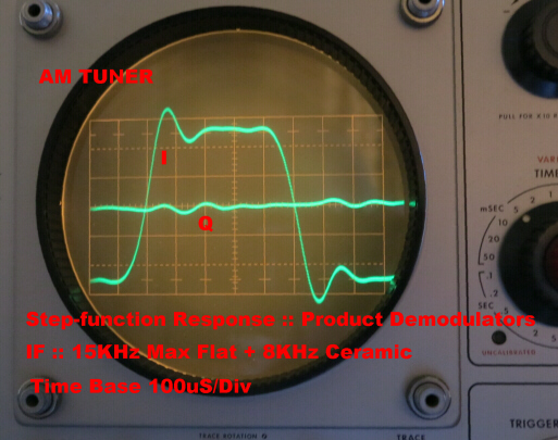 In this position two sharp cutoff ceramic filters are added in series
with the normal IF. The sharp cutoff causes ringing in the transient response.
The assymetry in the passband produces a significant quadrature component.
In this position two sharp cutoff ceramic filters are added in series
with the normal IF. The sharp cutoff causes ringing in the transient response.
The assymetry in the passband produces a significant quadrature component.
 AM allows the simplest demodulation of all modulation systems.
This was one of the reasons for its initial adoption in broadcasting.
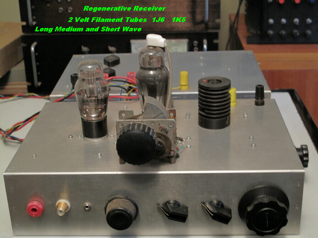
It is instructive to compare the performance of an early regenerative
receiver with the tuner.
AM allows the simplest demodulation of all modulation systems.
This was one of the reasons for its initial adoption in broadcasting.
It is instructive to compare the performance of an early regenerative
receiver with the tuner.
To do this I rebuilt my first receiver. It uses 2 volt filament tubes -
a 1K5 as a regenerative detector and a 1J6 double triode as a transformer
coupled audio amplifier.
Investigation with modern test gear revealed much more complicated circuit
behaviour than is described in text books - nonlinearities within nonlinearities-
yet the audio on modern headphones sounded remarkably clean.
Sample audio taken across the headphone jack is included.
top
back/home
GENERAL DESCRIPTION:-
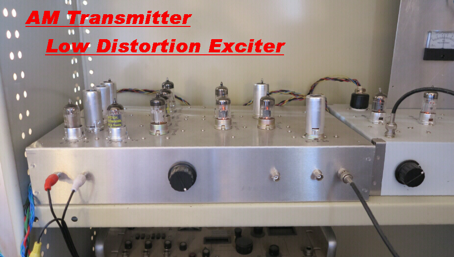
The transmitter is all vacuum tube and divided into two sections:-
(a) A low power exciter driving:
(b) A low distortion low power class A amplifier.
The exciter is shown in the photo on the right.
Modulation occurs in a 6AR8 beam deflection tube with heavy feedback
to improve the deflection linearity. The modulation process is virtually
distortionless.
The class A power amplifier has internal current feedback to reduce distortion.
Overall voltage feedback ensures that the bandwidth is independent of the load.
The amplifier will drive a wide range of inductive and capacitive loads.
DISTORTION:-
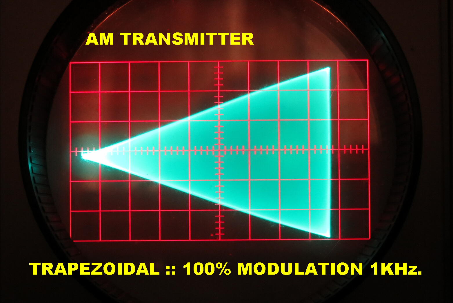 The classical method of examining distortion in AM transmitters and
receivers is the trapezoidal pattern.
The classical method of examining distortion in AM transmitters and
receivers is the trapezoidal pattern.
In transmitters the RF output is plotted against the modulating audio input
( usually sinusoidal).
In receivers the modulated RF input is plotted against the receiver audio output.
High level plate modulation is not an inherently linear process. Approximation
to linearity can be achieved by varing the RF load and modulation depth on the grid drive.
Trapezoidal patterns gave extremely useful information during this adjustment.
In many old receivers the detectors could not follow the modulation below about 10%
and this was usually the first cause of distortion to show up in a trapezoidal pattern.
In this transmitter and receiver the linearity is many orders of magnitude better than
deflection linearity of the oscilloscope -- so it is really test of the oscilloscope.
FREQUENCY RESPONSE:-
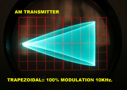 The trapezoidal pattern provides a quick and easy method of evaluating
the amplitude and phase response of an AM transmitter.
The trapezoidal pattern provides a quick and easy method of evaluating
the amplitude and phase response of an AM transmitter.
As the amplitude response falls off at high frequencies the pattern will change
from a triangle to a trapezoid. Phase change results in an ellipse on the sides
of the trapezoid.
The trapezoidal pattern for the transmitter at 10KHz. is shown.
Since the pattern is still a triangle, the response is flat to 10KHz.
and the narrow ellipse shows that there is a small phase change.
In fact the transmitter is flat from about 1Hz. to 40KHz.
TRANSIENT RESPONSE:-
 Since the transient response is uniquely related to the steady state
response, it provides a quick method of evaluating the dynamic behaviour of
a transmitter.
Since the transient response is uniquely related to the steady state
response, it provides a quick method of evaluating the dynamic behaviour of
a transmitter.
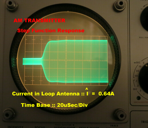
The step function response of the transmitter is shown. It plots the RF current
in a loop antenna for a step function input to the modulation input.
The response is fast with very little ringing.
top
back/home
OPENING REMARKS:-
When an AM signal is transmitted through a linear network of finite
bandwidth non-linear distortion may occur to the modulation content.
When an FM signal is transmitted through a linear network of finite bandwidth
non-linear distortion ALWAYS occurs.
Of course non-linear distortion in a linear network seems a contradiction. We must
regard the modulator, the transmission network and the demodulator as a unit. Since the
modulator and demodulator are both non-linear elements, non-linear behaviour
is really no mystery.
If product demodulators are used in an AM system no distortion can result from
transmission through a linear network. This is a very valuable property of
AM transmission.
HISTORY
 R.A Fessenden, a Canadian from Knowlton, Quebec, Canada invented and
patented AM in 1901.[ US Pat.753,863 ] One of his early ideas to produce
a high power AM transmitter without the use of vacuum tubes (invented 1906)
was to frequency modulate an arc transmitter with a condenser microphone
and turn this into AM by detuning the antenna system. He therefore was
aware of FM but did not patent it. This was done by C.D.Eheret of Chicago
in 1902.
R.A Fessenden, a Canadian from Knowlton, Quebec, Canada invented and
patented AM in 1901.[ US Pat.753,863 ] One of his early ideas to produce
a high power AM transmitter without the use of vacuum tubes (invented 1906)
was to frequency modulate an arc transmitter with a condenser microphone
and turn this into AM by detuning the antenna system. He therefore was
aware of FM but did not patent it. This was done by C.D.Eheret of Chicago
in 1902.
[ US Pats. 785,803 785,804 ]
For the historic broadcast from Brant Rock on Xmas Eve 1906, Fessenden
used a high speed variable reluctance alternator to generate the carrier.
The carrier was modulated by a water cooled carbon microphone in the
antenna matching network.
The signal was radiated from a 420 foot top loaded monopole.
The carrier frequency was probably 88KHz.
Tests of this AM transmitter were received in Machrihanish in Scotland in
November 1906 - the first transalantic audio.
top
back/home
A BRIEF ACCOUNT of AM and FM
AM
An AM signal is usually defined as:-
v = V[sin(wct)][ 1 + mcos(wmt)]
where wcis the carrier angular frequency; wm is the
angular modulating frequency; m is ihe modulation depth where:-
0 < m < 1
This expands to:-
v = V [ sin(wct) +(m/2)( sin(wc + wm)t
+sin(wc - wm )t )]
A carrier- an upper sideband - and a lower sideband.
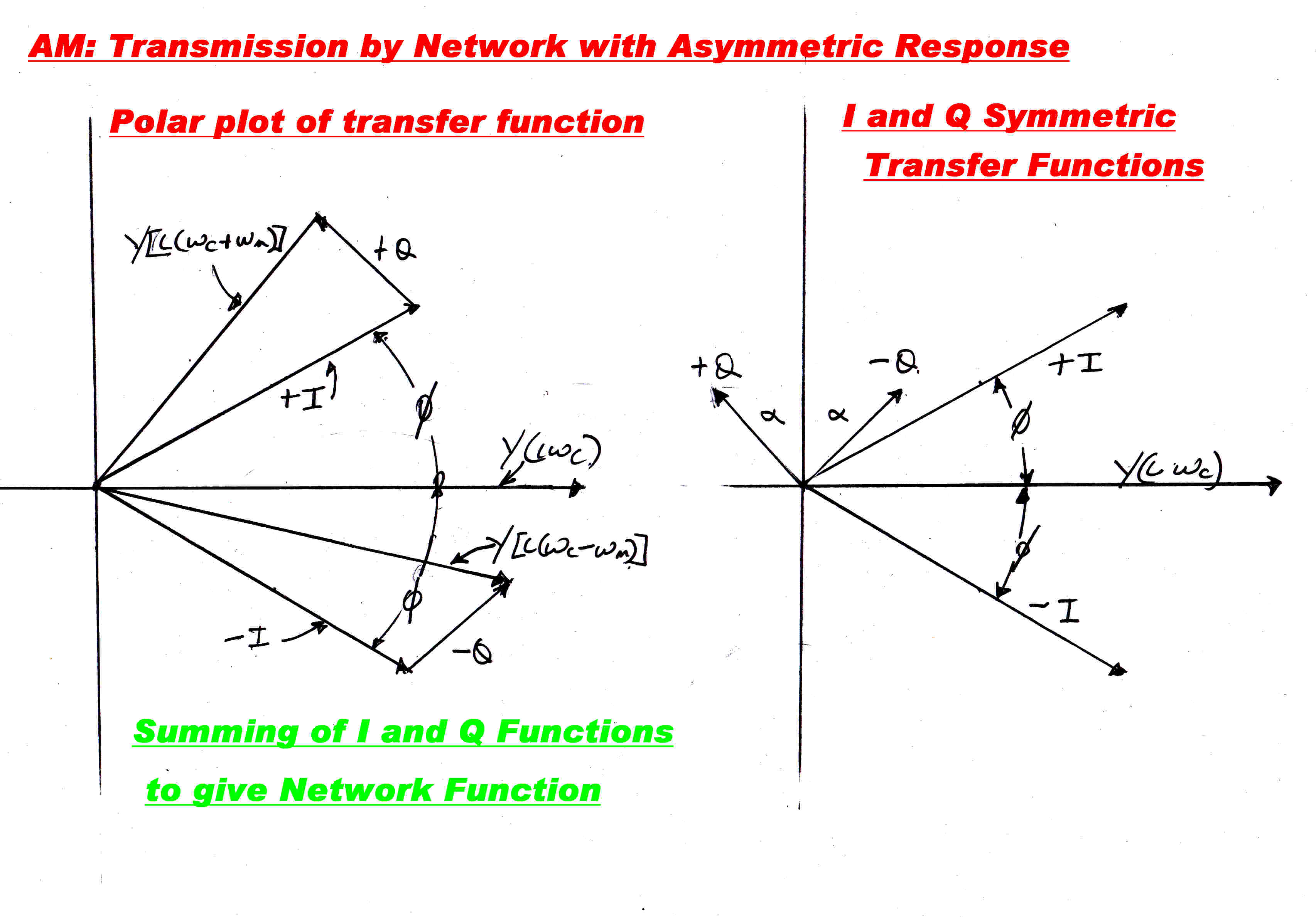
Note that an AM wave is characterised by complete symmetry between the upper
and lower sideband, but on passing through an asymmetrical network this symmetry
is destroyed. How do we deal with this?
We employ the same algebraic trick power engineers use to render unbalanced three phase
systems into three symmetrical - and hence calculable - components:- two completely
symmetrical three phase components rotating in opposite directions and a third
common mode component.
Here we imagine the transmission network to be made up of two channels in parallel;
one with symmetry about the real axis and one with symmetry about the imaginary axis.
The imaginary axis implies modulation on a quadrature carrier.
Let the transfer function of an AM channel be YTi( wc + wm )
Form a normalised transfer function Yi( wc + wm ) by making:
Yi( wc + wm ) =
YTi( wc + wm)/YTi( wc )
At carrier frequency wm = 0 so that:
Yi( wc ) =
YTi( wc )/YTi( wc )
This has a magnitude of 1 and an angle of 0 degrees.
Let the two component transfer functions with symmetry be:-
YIi( wc + wm ) for the IN phase channel and:
YQi( wc + wm ) for the QUADRATURE phase channel.
Then two simultaneous equations can then be written equating the components of the upper
and lower sidebands.
The solution of these equations gives:-
YIi( wc + wm ) = [1/2][ Yi( wc + wm)
+ Y*i(wc - wm) ]
YQi( wc + wm ) = [1/(2i)][ Yi( wc + wm)
- Y*i(wc - wm) ]
Note: Y* implies conjugation.
Where YIi( wc + wm ) is transfer function of the I or
IN PHASE CHANNEL and
YQi( wc + wm ) is the transfer function of the Q or
QUADRATURE CHANNEL.
Note that the quadrature channel has no carrier-- suppressed carrier modulation.
This can be seen by putting wm to 0
The equation for the quadrature transfer function then becomes:
YQi( wc ) = [1/(2i)][ Yi( wc )
- Y*i(wc ) ] = 0
If I(t) and Q(t) are the amplitudes on the two channels then, since the carriers are in
quadrature, the envelope amplitude, E(t) will be given by:-
E(t) = [ I(t)2 + Q(t)2](1/2)
And the phase modulation ,Θ(t), is given by:-
Θ(t) = tan-1( Q(t)/I(t) )
We have the result that any mechanism which causes asymmetry in an AM transmission network,
such as detuning of the receiver or multipath, will cause distortion if envelope detection
is used.
With product demodulation - where a locally generated carrier is multiplied with the AM signal-
no distortion occurs.
We can express the output,v(t), from the I and Q channels as:-
v(t) = [ 1 + I(t)]sin(wc)t) + Q(t)cos(wct)]
If we multiply this by a locally generated inphase [sin(wct)]
and quadrature [cos(wct)] carrier
we get vout(t) where:-
vout(t) = v(t)sin(wct)
= sin(wct) + I(t)( sin2wct) ) +
Q(t)sin(wct)cos(wct)
= sin(wct) + I(t)( 1/2)( 1 - cos(2wct)) + Q(t)(1/2)sin(2wct)
This contains a baseband signal, (1/2)I(t), and components at the carrier frequency and
twice the carrier frequency. After passing through a low pass filter we are left with I(t).
Similarly, if we multiply by cos(wct) we are left with Q(t).
If we multiply by sin(wct + φ) we get:-
V(outt) = I(t)cos(φ) + Q(t)sin(φ)
A general conclusion about AM transmission can now be made:-
If product demodulation is used in AM transmission, the demodulated output can be
described as the sum of the solutions of two linear differential equations for transmission
through ANY linear network.
top
back/home
FM
INSTANTANEOUS and STEADY STATE FREQUENCY
Although patented in 1902, the true nature of FM was not understood,
probably up until Carson's paper in 1922.
John R Carson. Notes on the Theory of Modulation. Proc. IRE Feb. 1922.
The steady state circuit theory used to evaluate its performance was not applicable.
The classical solution of a linear differential equation for a network consists of two parts:-
[1] A particular solution -- The steady state component.
[2] The complementary function -- The transient terms.
In the steady state solution the transient terms are neglected. It is assumed the response
is taken after all the transient terms have died down. This is inadmissable in an FM signal
for, by its very nature, it is constantly changing and exciting transients.
In FM we deal with instantaneous frequency NOT steady state frequencies.
If the FM modulating signal changes only very slowly, then the transient terms will drop
out and the instantaneous frequency approaches the steady state frequency.
Many FM systems - such as Foster - Seely discriminators and Ratio Detectors - are designed
intuitively using steady state equations. Their behaviour at high modulating frequencies
often differs markedly from that predicted by the steady state design equations.
In a signal defined by the equation:-
v(t) = sin( Φ(t) )
the angular instantaneous frequency, Ω(t), is defined as:-
Ω(t) = dΦ(t)/dt
and the instantaneous frequency, f(t), is given by:-
f(t) = Ω(t)/( 2 Π )
In frequency modulation Φ(t) is defined as:-
Φ(t) = ωc t + ∫fm(t)dt
where fm(t) is the modulating signal.
So that the instantaneous frequency, Ω(t), becomes:-
Ω(t) = ωc + fm(t)
Virtually all the properties of FM can be understood
from the study of a simple* equation.
If two sinusoids of diffefrent angular frequencies
ω1 and ω2 and different amplitudes A and B are
added algebraically, we get:-
v(t) = Asin( ω1t ) + Bsin( ω2t )
The instantaneous frequency, Ω(t), of the sum is given by:-
Ω(t) = ω1 +
(ω2 - ω1)[ (B/A)2
+(B/A)cos( ω2 - ω1 )t )] /
[ 1 + (B/A)2 +
2(B/A)2cos( ω2 - ω1 )t ]
And the amplitude, E(t), is given by:-
E(t) =
[ 1 + (B/A)2 +
2(B/A)2cos( ω2 - ω1 )t ](1/2)
We can now rewrite the instantaneous angular frequency, Ω(t), as:-
Ω(t) = ω1 +
(ω2 - ω1)[ (B/A)2
+(B/A)cos( ω2 - ω1 )t )] / [ E(t) ]2
* Although the equation is simple, its derivation
does involve some nasty algebra.
THE FM COMPONENT OF TWO ADDED SINUSOIDS IS A NON-LINEAR FUNCTION.
THIS IS THE BASIC MECHANISM OF DISTORTION IN FM TRANSMISSION.
If the first sinusoid is assigned to the FM carrier, then the other may be
due to transients in a transmission network or an interfering signal caused by
multipath transmission. All will produce distortion in the FM modulation content.
In practice we have to design the bandwidth and phase response of
the FM transmission network to reduce the level of the induced transients - and hence the
distortion - to an acceptable level.
We have control over the networks in the transmitter and receiver but less control
over multipath when the signal is radiated.
 The graph shown opposite plots the instantaneous frequency for two
ratios of sine wave:- B/A = 1.32 and B/A = 1.05.
The graph shown opposite plots the instantaneous frequency for two
ratios of sine wave:- B/A = 1.32 and B/A = 1.05.
As the ratios approach unity the amplitude of the envelope tends to zero
and, since it is the denominator, the FM has a large peak. It is therefore
possible for the response of an FM system to exhibit singularities when
the amplitude approaches zero.
This presents a puzzle for, in any network of finite bandwidth, the
rate of change can only be finte.
Imagine the FM component given by the inverse of the time between zero crossings.
If the amplitude is very small, the signal can cross and recross zero
in very short times, even with a finite rate of change, and so very large spikes
can be generated in the FM response.
Since FM distortion is accompanied by amplitude modulation, it seems prudent to
equip FM tuners with an envelope detector before limiting to give an indication
of multipath distortion.
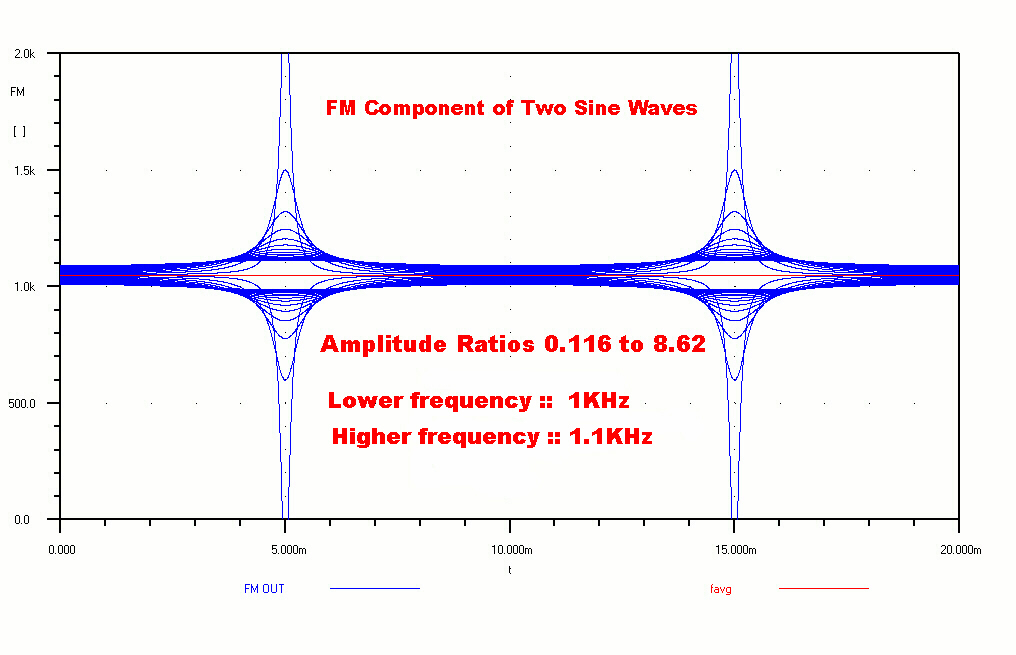 If we plot the above equation for B/A ratios between 0.116
and 8.62 we get the plot shown on the right.
If we plot the above equation for B/A ratios between 0.116
and 8.62 we get the plot shown on the right.
For B/A = 1 the expression becomes indeterminate, but just on either
side it is very large indicating a singularity.
STEP FUNCTION RESPONSE
 FM analysis usually throws up horrific algebra because of
its non-linear nature. It is possible to get closed algebraic
solutions for the step function response in some cases.
FM analysis usually throws up horrific algebra because of
its non-linear nature. It is possible to get closed algebraic
solutions for the step function response in some cases.
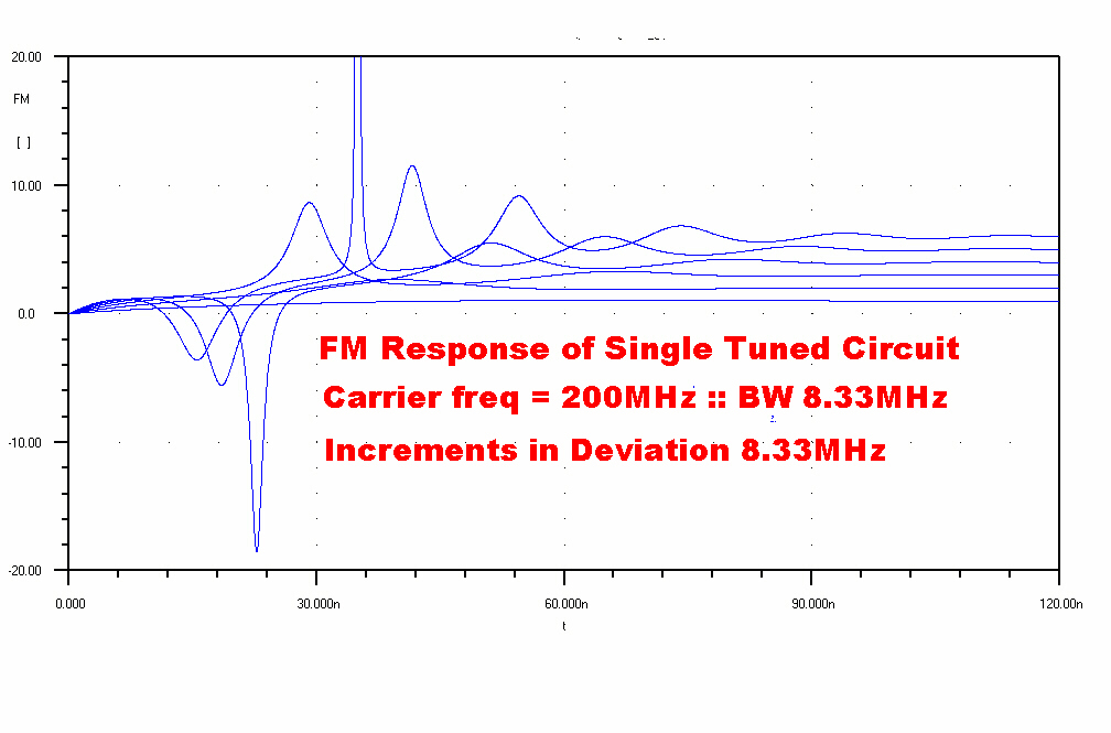
A plot of the step function response to a single tuned circuit
is shown on the right.
If we increase the deviation, the underlying non-linearity of the
response is apparent.
The general solution for the response of a single tuned circuit to
an FM step function of wb from the centre frequency is given by:-
Ω(t) = [ 1 + ( exp( - wbt )) sin(φ)
{ ( wm/wb - wb/wm )cos ( wmt - φ )
+ 2sin( wmt - φ ) }] /
[ 1 + (( wm/wb)2 )
( exp(-2wbt) ) + 2exp( -wbt )sin(φ)
{ (wm/wb )cos( wmt - φ )
+ sin( wmt - φ ) } ]
where:-
Ω(t) = FM response
tan(φ) = wm/wb
wb = wc/( 2Q )
wm is the frequency deviation ( rad/sec) on the carrier
wc is the centre frequency of the carrier and tuned circuit
wb is the bandwidth of the tuned circuit with quality factor Q
The complexity of the solution, together with the possibility of singularities,
is an indication of the highly non-linear nature of FM.
AN FM MYTH
One often sees explanations like the following to explain
noise reduction in FM:-
"A noise signal adds to a modulated wave to produce changes in
amplitude, so an FM receiver which responds only to FM ignores it."
This is both simplistic and wrong.
Any signal added to a modulated wave pulls the zero crossing points,
and so adds FM modulation to the wave. No amount of amplitude limiting
will remove it.
Armstrong did not invent FM. He simply realised that the deviation
could be increased to compete with the noise.
NOISE
In any transmission system we can decrease the noise
by decreasing the sensitivity of the receiver while still keeping
a constant signal output.
In AM we have only one degree of freedom, and so have to increase
the transmitter power output.
In FM we have two degrees of freedom: transmitter power and frequency deviation.
The price we pay for increased deviation is an increase in transmission bandwidth
and a greater propensity for distortion.
Suppose we regard the noise vn(t) in an FM system as a small
disturbing sinsuoid given by:-
vn(t) = Bsin( ωnt )
added to a carrier given by:-
vc(t) = Asin(ωct )
where B/A << 1
The above equation reduces to:-
Ω(t) = ωc +
(ωn - ωc )
( B/A )cos(ωn - ωc)t
Because of the term (ωn - ωc ) the
frequency modulation due to noise increases linearly with separation from the carrier.
The noise is BLUE.
Pre-emphasis is used to overcome this. It is a mixed blessing.
While it reduces "blue" noise, it can increase distortion on fast transients.
In a sense, the benign nature of AM is its own worst enemy.
It will accomodate poorly designed narrow band IF strips in cheap
receivers without the introduction of distortion.
The same technique in an FM tuner results in horrendous distortion: so FM tuners
are - of necessity - broadband.
Note that all these desirable characteristics apply
only to pure AM. Any attempt to multiplex with any other form of modulation,
say FM for stereo, can introduce horrendous distortion.
This was discovered as early as 1926 by Bell* engineers.
At that time the transmitters used L-C oscillators sharing a common power
supply with the modulators. The lack of regulation caused FM modulation, and this
resulted in bad distortion in the received signal.
This was one of the reasons for the adoption of quartz crystal oscillators.
* Some Studies in Radio Broadcast transmission.
Ralph Brown: DeLoss K Martin: Ralph K Potter
Bell System Telephone Journal January 1926 pp `143 -- 213
top
back/home
In AM reception on the broadcast band, loop aerials can reject
unwanted signals in two ways:-
[1] Loop aerials are directional and have no response to signals arriving at
right angles to the plane of the loop.
The polar plot of the response is sinusoidal, so that if the interfereing
signal arrives at a significant angle from the wanted signal, it
can be eliminated.
[2] Loop antennas are responsive to the magnetic component of a signal since:-
Vout = ∫∫ ∂B/∂t •dA
For locally generated near fields, the electric component overwhelms
the magnetic component. An antenna responsive to the magnetic component, rather
than the electric component, will therefore tend to minimise locally
generated noise.
Any local noise generator, such as an arcing commutator, can be regarded as
being made up of elementary current elements represented by
Idlcos(ωt).
Where I is the peak current along a vector element dl.
Charge will acumulate at the ends of the current element, and will
be at a maximum when the current goes to 0.
The accumulated charge Q on the ends of the element is given by:-
Q = ∫Icos(ωt)dt = (I/ω)sin(ωt)
So that the peak charge Qp = I/ω
The current element I becomes a doublet or dipole of charge of moment M where:-
M = (Idl/ω)sin(ωt)
Now Maxwell's Equations have charge conservation inbuilt
(see below),
so the general solution for the oscillating current element will
automatically include the field of the electrostatic doublet or dipole.
We now solve for the complete field surrounding such an element:-
General Solution of Field Surrounding Oscillating Current Element
Consider a current element I dl cos(ωt)
placed at the origin
with the vector dl on the z axis.
Then, using the usual spherical coordinate designations, we have:-
Eθ = [(Idlsin(Θ))/4πε]
[ sin(ωt′)/ωr3 +
cos(ωt′)/r2c -
ωsin(ωt′)/rc2 ]
Er = [(2Idlsin(Θ))/4πε]
[ sin(ωt′)/ωr3 +
cos(ωt′)/r2c ]
HΦ = [(Idlsin(Θ))/4π]
[ cos(ωt′)/r2 -
ωsin(ωt′)/rc ]
where r, Θ, Φ are usual spherical coordinates.
t′ = t - r/c : delayed time.
c = velocity of light = 1/[με]1/2
Discussion of General Solution
We now examine the terms one by one:-
[A] The third term of the form: - ωsin(ωt′)/rc
(1) Since this term varies as 1/r and the other terms as
1/r2 and 1/r3, it will eventually predominate and
is the radiation term.
(2) Since dcos(ωt)/dt = - ωsin(ωt), it depends on the derivative
of the current: that is the acceleration of the moving charge.
(3) The ratio E/H is 1/εc
Since c = 1/[με]1/2,
E/H = intrinsic impedance of free space
= [μ/ε]1/2 = 377 ohms (MKS)
[B] The second term of the form: cos(ωt′)/r2
(1) The magnetic field H is simply that predicted by Ampere's law, but with a time delay.
Ampere's law for the current element Idl is:-
dH = [I dl x (r/r)]/r2
[C] The third term of the form: sin(ωt′)/ωr3
(1) The electric field is that predicted for a charge doublet of
moment M = (Idl/ω).
(2) The electric and magnetic fields are in quadrature as expected.
(3) The 1/ω term means the interference is worse at the low
frequency end of the broadcast band.
(4) The 1/r3 term means that this term will
dominate near the source of the noise.
(5) By equating terms, the radius R where the 1/r3 term dominates is given by:-
R = λ/2π
In the middle of the broadcast band this is about 50 metres. The field from any source
of interference within a house will therefore be predominantly electric.
A well screened loop antenna does not respond to this: an extremely
valuable property.
To show that Maxwell's Equations have charge conservation inbuilt.
We have:-
∇xH = J + ∂D/∂t
Take the divergence of both sides:
∇•(∇xH) = ∇•J +
∇•(∂D/∂t )
But: ∇•(∇xH) = 0
So that: 0 = ∇•J + ∇•(∂D/∂t )
And: ∇•J = - (∂∇•D/∂t )
But from Maxwell: ∇•D = ρ
Substituting: ∇•J = - (∂ρ/∂t )
Using Gauss' Theorem: ∫∫J•dA =
∫∫∫∇•JdV
Therefore: ∫∫J•dA = -
∫∫∫∂ρ/∂t dV
Now ∫∫J•dA is the total current flowing out of
the enclosed space and ∫∫∫∂ρ/∂t dV is the total
loss of charge. Since the two are equal charge is conserved.
top
back/home
This site is a reaction, in part, to the modern
tendency to denigrate the AM service.
This practice seems almost universal in presenters of the national
broadcaster.
Although their knowledge of modulation theory and transmitter
design is probably minimal, they never miss an opportunity at
dissmissing the AM service as "old and scratcy".
As pointed out above, AM on the broadcast band is capable
of providing a high quality monophonic signal to a wide audience -
admirably suited to Australian conditions.
For "boutique broadcasting" or narrowcasting FM does offer some advantages.
[1] In FM transmitters modulation is at a low level and is followed by saturated
or "bottomed" RF stages. This permits high efficiency with ease of adjustment.
Ampliphase or "Chiriex" modulation allowed the same technique to be used in
vacuum tube AM transmitters. Many of these were let down by poor circuit design,
and the departure from normal pracrice was not popular with many transmitter technicians.
Many modern AM transmitters use class E mosfet power amplifiers. In these the active elements
run saturated, so the difference between AM and FM transmitters has largely disappeared.
[2] As pointed out above, an FM transmitter with a deviation of +(-) 75KHz must occupy
a bandwidth of about 100KHz to keep the non-linear distortion to a manageable level.
It is easy to show that, in the limit, the transfer function for the FM modulation is
the same for AM modulation.
The bandwidth for the FM channel modulation content is then about 100KHz wide.
This allows for the addition of
high frequency sub-carriers - one for stereo and the possibility of more
for other services. The only disadvantage is that the deviation on the base band channel
has to be decreased.
[3] FM antennas can usually be added to existing TV towers with a minimum of cost.
Further, these antennas usually have sufficient bandwidth to accomodate the complete
FM band, so that multiplexing is possible for a number of FM transmitters.
[4] The process can be repeated from city to city without danger of interference.
Night time propagation on the broadcast band which used to be a strength, is now
a mixed blessing.
[5] AM stations with monopole radiators of approxmately half wavelength occupy a fair area,
usually around swampy ground. These sites are becoming more difficult to find.
[6] The broadcast band is more than fully occupied, so that no more AM services are possible.
This is a plea to value the AM services we have, particularly the high power transmitters
used for the national service.
[7] The root of most of the criticism of the AM service is the extremely poor performance
of imported receivers. With modern integrated circuit technique and mechanical
filters there is no excuse for this.
 Although programs with a 9KHz cutoff can still sound remarkably bright,
it should be possible to operate the AM service with full bandwidth, at
least during the day.
Although programs with a 9KHz cutoff can still sound remarkably bright,
it should be possible to operate the AM service with full bandwidth, at
least during the day.
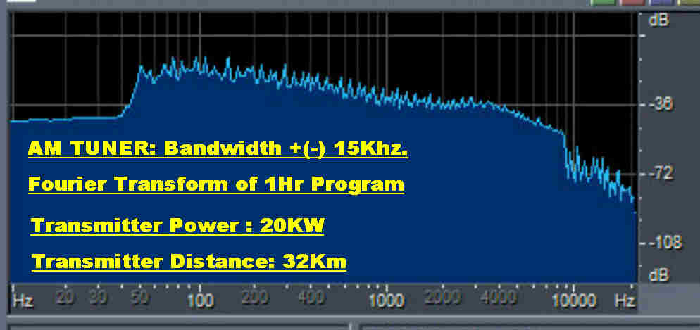
It has come as a suprise that the tuner can be operated with a bandwidth of
+(-)15KHz in a built up suburban area during the day without noticeable noise.
A Fourier transform of an hour long program is shown.
The 9KHz sharp cutoff at the transmitter is apparent. It would seem that there
is also a low frequency cutoff about 50Hz.
top
back/home
|