PREAMPLIFIER and UNIVERSAL DISC EQUALISER
CONTACT : COMMENTS AND QUESTIONS
back/home
This section describes a vacuum tube preamplifier and disc equaliser.
The next section describes a universal tone control.
These, together with the either the 6V6 or 6L6 power amplifier and the regulated power supply, combine to form a high
quality vacuum tube audio system.
PREAMP
(1) To accomodate magnetic cartridges of varying sensitivity, the gain of
the preamplifiers can be adjusted over wide limits - 21 (26db) to 221 (47db)
(2)The preamplifiers are switched to respond to three recording modes:-
(a) Stereo
(b) Lateral Monaural
(c) Vertical Monaural [ Hill and Dale ]
The relative gain between the channels can be altered to optomise performance.
For instance: The track on an Edison Diamond disc has only vertical modulation, so the system should be
unresponsive to lateral modulation.
To ensure this the disc is first played with the control in the LATERAL position
and the relative channel gains adjusted for minimum output.
When playing a mono disc with lateral modulation, the system is adjusted for zero
vertical rersponse to suppress distortion due to pinch effect.
DISC EQUALISER
The disc equaliser has the following functions:-
(a) Constant Velocity for Acoustically Recorded discs.
(b) Constant Amplitude below 250 Hz - constant velocity above.
(c) Constant Amplitude below 500Hz - constant velocity above.
(d) Constant Amplitude from 150Hz to 750Hz continuously variable - constant
velocity above.
(e) Constant Amplitude below 250 Hz - variable cut from 1.8KHz to 10KHz.
(f) Constant Amplitude below 500Hz - variable cut from 1.8KHz to 10Hz.
(g) Constant Amplitude from 150Hz to 750Hz continuously variable - variable cut
from 1.8KHz to 10KHz
(h) 78 RIAA
(i) Stereo RIAA
 The block diagram of the disc player is shown opposite:-
The sum and difference of the two channels appears on the left hand equaliser and tone control,
so both output amplifiers are driven from the LHS in the mono positions.
Because of the low signal levels, noise and hum, not distortion, pose most of
the problems in the design of the preamplifier.
THERMAL NOISE
It is good practice in feedback amplifier design to form the error signal in a passive network
and apply it to the input grid. The passive network is usually about the 100k impedance level
and introduces a significant amount of thermal noise, so it is not attractive in low
level amplifiers.
In low level amplifiers the grid impedance should be the impedance of the signal generator
( magnetic cartridge ) and the feedback introduced into the cathode of the first stage.
HUM
The heater to cathode capacity of an EF86 is about 5pF, and this can inject 50Hz hum into
the cathode if it is not heavily bypassed to bring it near earth potential : so we desire that all
cathodes in a low level preamplifier be bypassed with a large capacitor.
The resistor introduced into the EF86 cathode for feedback therefore should have a low value.
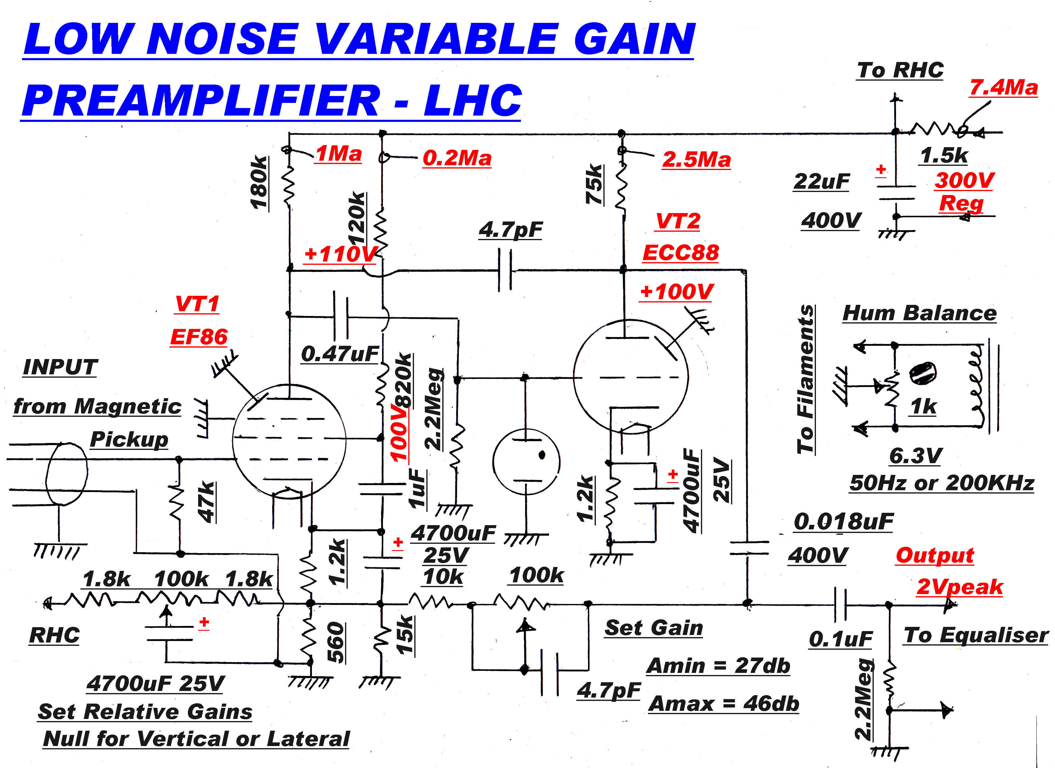
The circuit of the preamplifier is shown below.
THERMAL NOISE
The RMS thermal voltage Vt across a resistor is given by:-
Vt2 = 4kTBR
where :-
k (Boltzmann's constant ) = 1.381 x 10⁻²³ J/oK
If T = 300oK: B = 20KHz: R = 100k
Then Vt = 5.757 microvolts - significant in this context.
SHOT NOISE
where: e = charge on electron = 1.6022x10⁻¹⁹ coulombs
And I = 1MA (DC): B = 20KHz
So: Isn = 2.5314 x 10⁻⁹ Arms
But the Gm of the EF86 = 1.5 x 10⁻³ A/V
So the effective shot noise on the grid is: Isn/Gm = 1.69 microcolts (RMS)
The valve data claims that the total noise referred to the grid is about 2 microvolts.
The extra noise is made up of partition noise introduced by the screen current and
flicker noise at low frequencies.
Hum suppression poses the most difficult problem in the design and construction of
high gain preamplifiers.
For all positions except "constant velocity", the disc equaliser introduces an
extra 20db of gain at 50Hz. This exacerbates the problem.
Hum is introduced into the first (EF86 ) stage through two paths:-
(1) Capacity between the grid and the two heater leads
(2) Capacity between the cathode and the heater within the tube.
In an EF86 this is about 5pF.
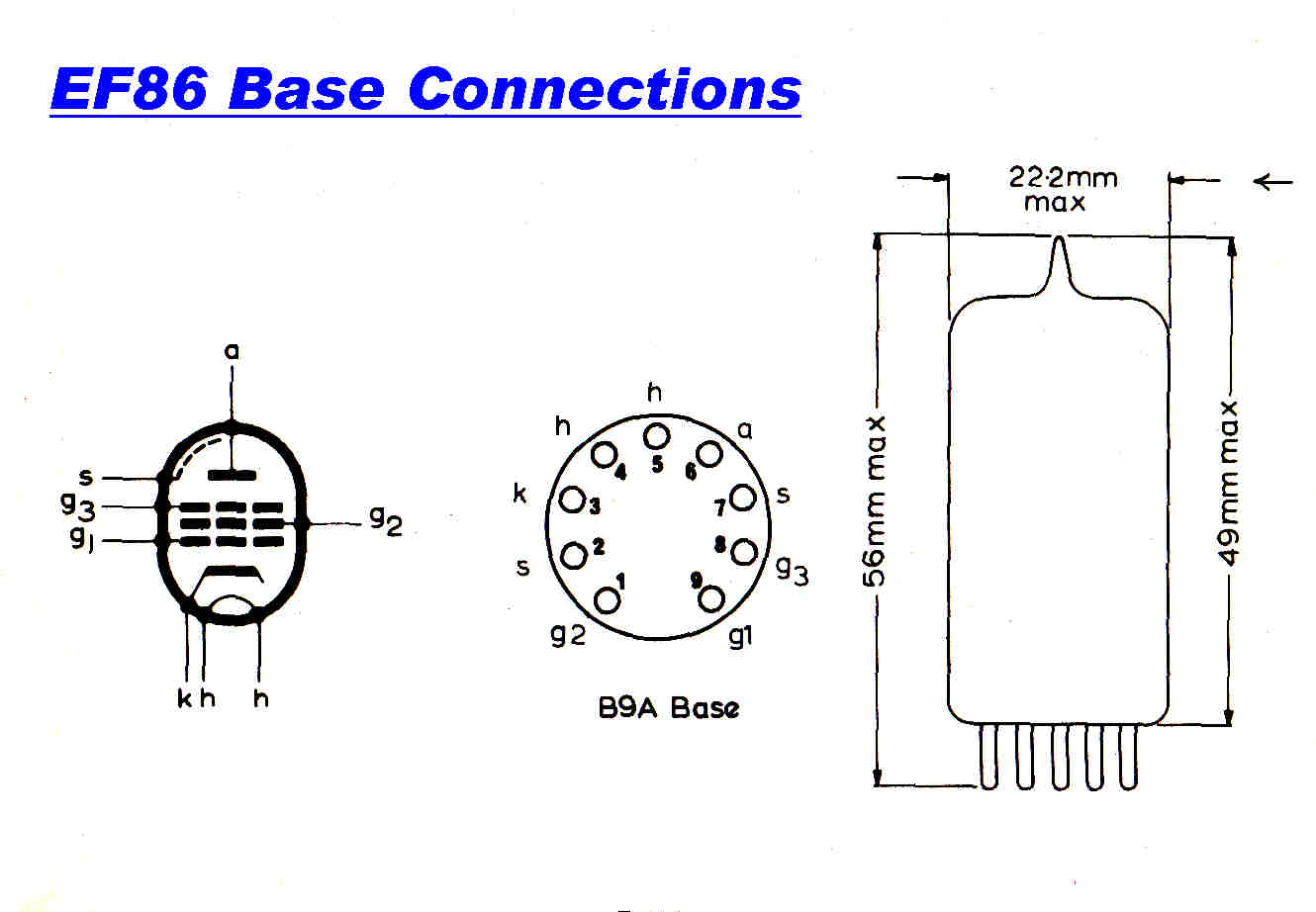
The design of the EF86 has special features to reduce hum as shown below.
|
|
|
The base of the EF86 is arranged for minimum capacitive coupling between
the grid (pin 9 ) and the 6.3 volt AC on the filaments pins (4 ,5 ). |
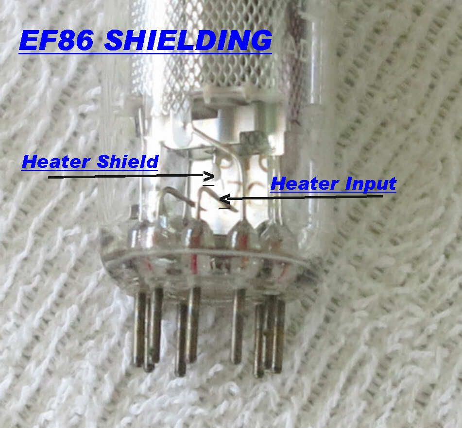
The internal rectangular shield in the EF86 between the grid and
the filament supply. |
 The comments on the EF86 in the Mullard valve handbook are shown opposite.
Note that hum may be eliminated completely if the filaments are energised from either DC
or high frequency AC.
DC
The large capacitors and inductors involved make its use unattractive.
AC
Usually about 200KHz generated by a twin triode push-pull oscillator with a ferrite
transformer. The oscillator uses the 300 volt regulated rail.
The total filament power for both preamplifiers is 4.8 watts.
There are some problems with the use of a 200KHz high frequency oscillator:-
(1) The audio system will usually incorporate a high quality AM tuner and harmonics
from the oscillator may coincide with one of the AM frequencies.
The oscillator should be active only while playing discs, so the switching
should be in the filament of the oscillator tube.
This causes a delay of about two filament warm up times on switchiong on -
about 40 seconds.
(2) The cold resistance of an EF86 filament is 4.26 ohms. This rises to 31.5 ohms.
Because the oscillator is initially heavily loaded, starting can be a problem.
HUM CANCELLATION
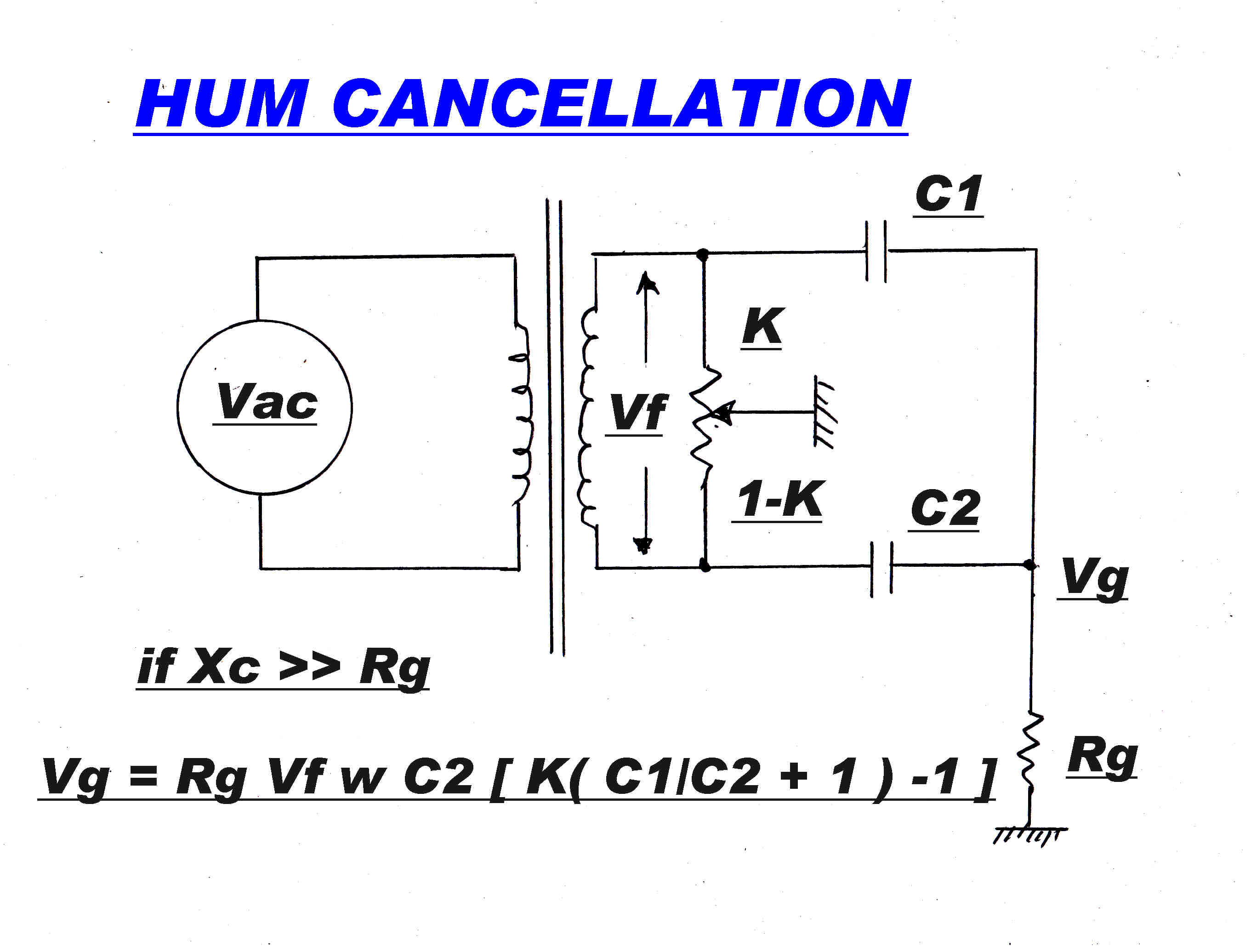 Capacitively induced hum may be cancelled by the bridge circuit shown opposite.
For the grid Rt is the impedance of the magnetic cartridge.
For the Stanton 500 MKII cartridge:-
R = 535 ohms: L = 400mH : |Z| = 549.6 ohms at 50Hz.
C1 and C
For the cathode, the resistance is the feedback resistor - 500 ohms -
paralleled with the resistance looking into the cathode of the EF86 - 1/Gm
Gm = 1.5Ma/V, so R|| = 285.8 ohms.
C1 and C2 are fixed by the heater to cathode capacity of the EF86
- 5 pF , so C1 = C2 = 2.5pF
From the above figures it would appear that cathode induced hum is more serious
than grid induced hum.
The worst case without cancellation is given when K = 1 .
For this case V = 0.224 μV .
The change in the overall gain of the preamplifier from 26db to 46db is achieved
by varying the feedback.
The steady state and transient response must not be affected unduly by the variation
in feedback
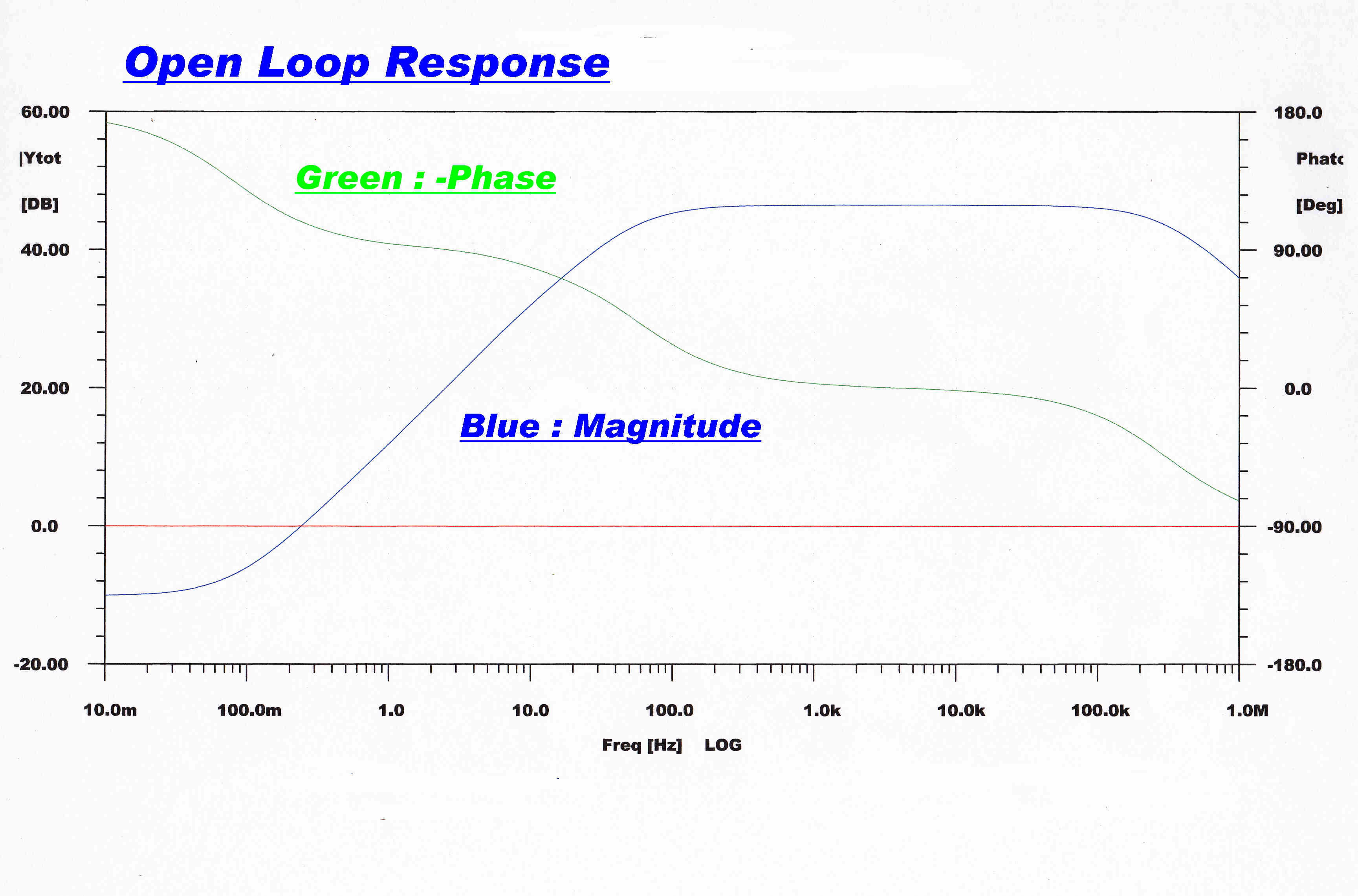
HIGH FREQUENCY STABILITY
The EF86 acts as a current generator driving into the grid of the ECC88.
The grid plate capacity of the ECC88 (1.4pF) together with the 4.7pF feedback capacitor
produce a pole on the real axis to stabilise the high frequency response.
The pole is chosen to make the overall response 3db down at 80KHz in the maximum gain
position.
The response extends out to 1.1MHz in the minimum gain position.
LOW FREQUENCY STABILITY
The low frequency transfer function in the forward path is of high order and
presents two problems:-
(a) Loop Stability
(b) Maintaining a desirable closed loop response while the feedback is changed by 20db.
Networks affecting the low frequency transfer function are:-
(1) The bypass capacitor - bias resistor in the cathode of the EF86 - producing :-
a pole and zero on the negative real axis.
(2) The screen bypass capacitor - feed resistor of the EF86 - producing :-
a pole and zero on the negative real axis.
(3) The coupling capacitor - grid resistor into the grid of the ECC88 - producing :-
a pole on the negative real axis and a zero at the origin.
(4) The output DC blocking capacitor - feedback resistor - producing :-
a pole on the negative real axis and a zero at the origin.
Note: The HT decoupling network has only a very small effect on the response and can be
neglected in the initial design .
The following strategy is adopted in the design of the low frequency feedback:-
(1) The feedback resistor Rf ( 10k to 110k ) also determines the time
constant τ of the output network, so its time constant varies with the feedback.
where : τ = ( Rf + Rb) Cb
where Cb is the 0.018uF blocking capacitor:: Rb is the bottom R
of the divider (500 ohms ).
(2) The output time constant τ is made much smaller than all the other time constants,
so it is this time constant which dominates and determines the low frequency forward
transfer function.
(3) The increase in feedback combined with the decrease in time constant give a constant
closed loop low turnover frequency independent of the feedback.
Using the approximations described above:-
τ = RfCb
so fol = 1/ 2πτ =
1/ 2π ( Rf + Rb ) C
The attenuation A in the feedback network is given by :-
A = Rb/( Rf + Rb )
The closed loop turnover frequency fcl is given by:-
fcl = fol/A so:-
fcl = [ 1/ 2π ( Rf + Rb ) C
so
fcl = 1/ 2π Rb C
THE TURNOVER FREQUENCY UNDER FEEDBACK IS INDEPENDENT OF THE AMOUNT OF FEEDBACK
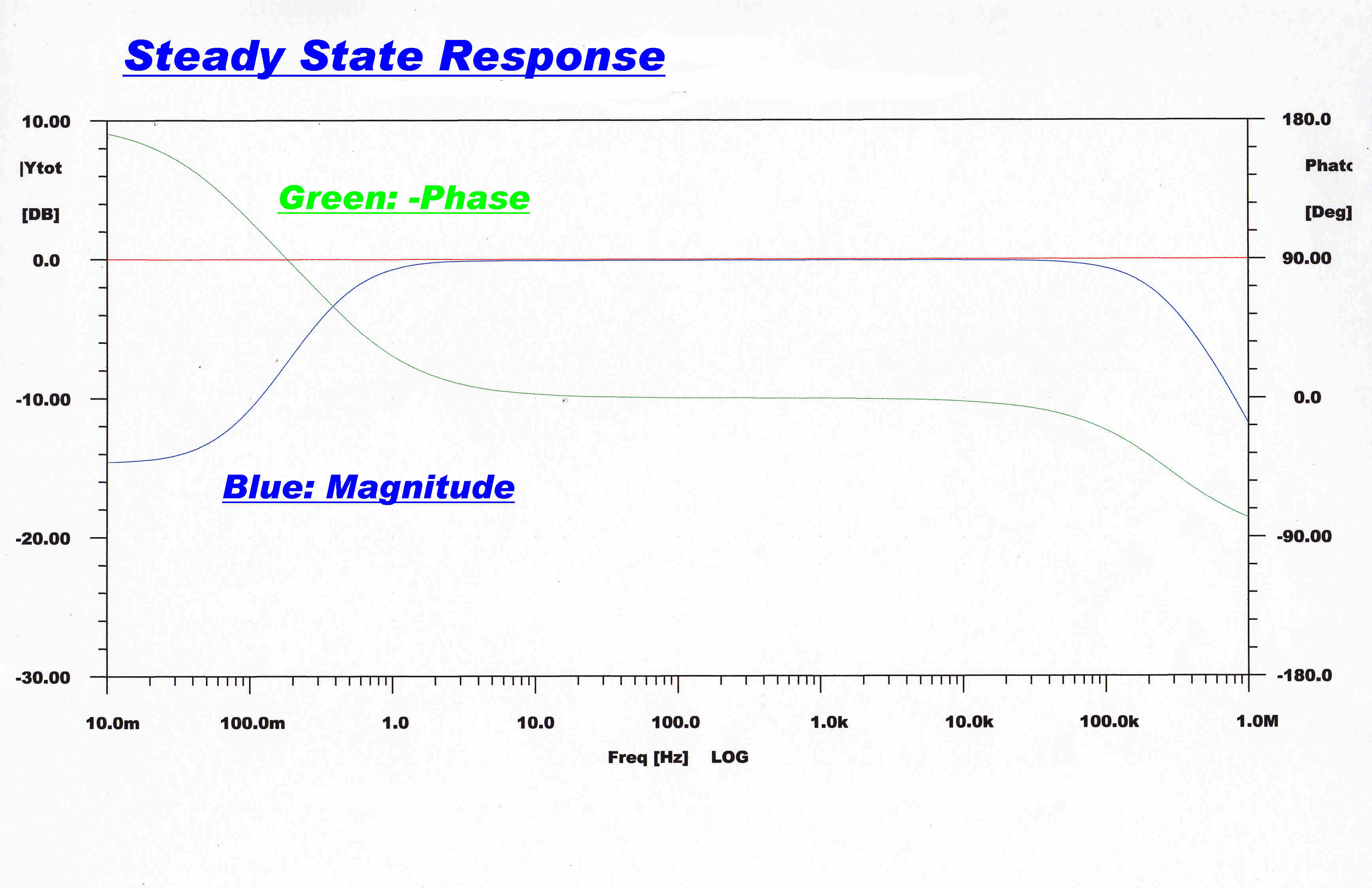
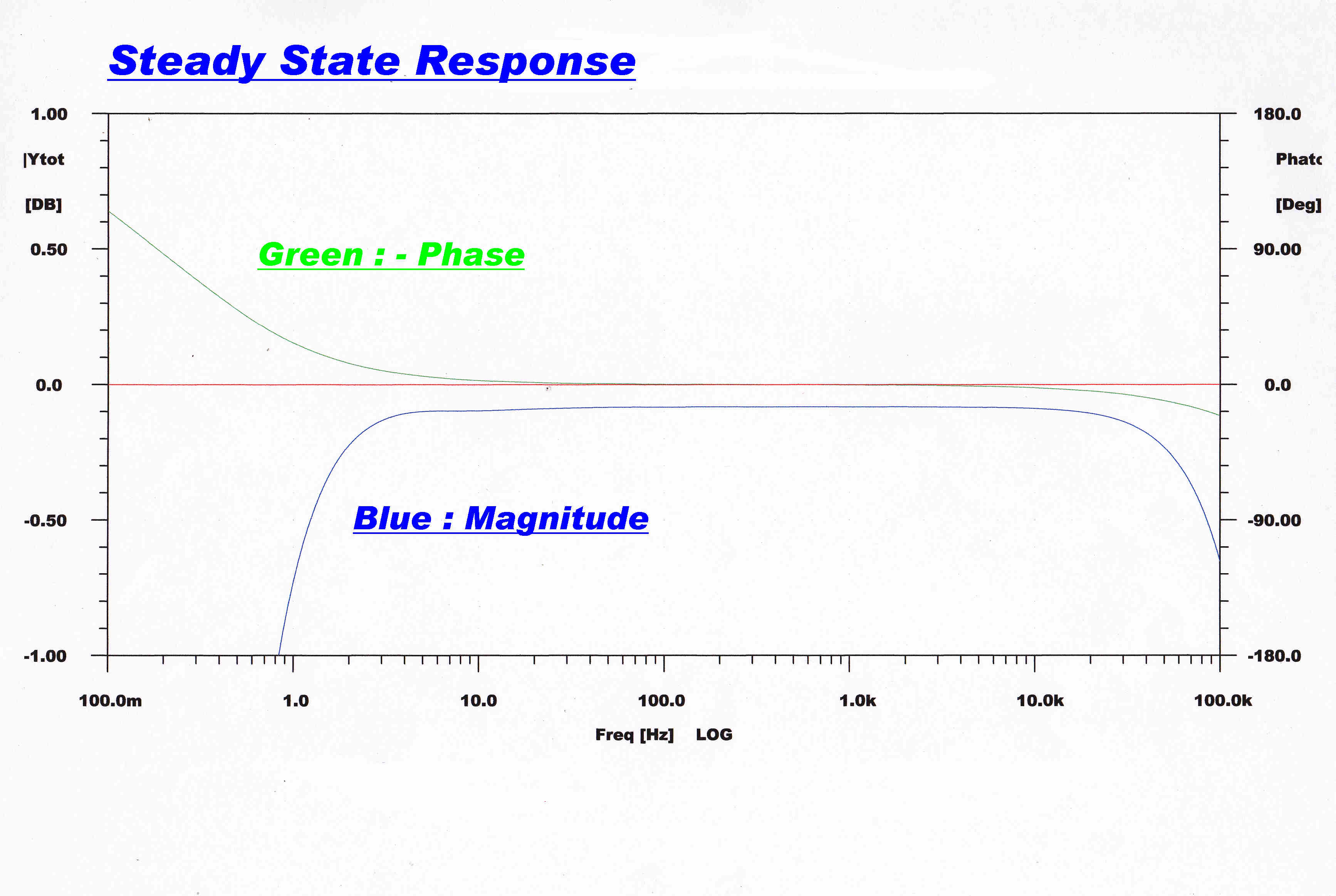
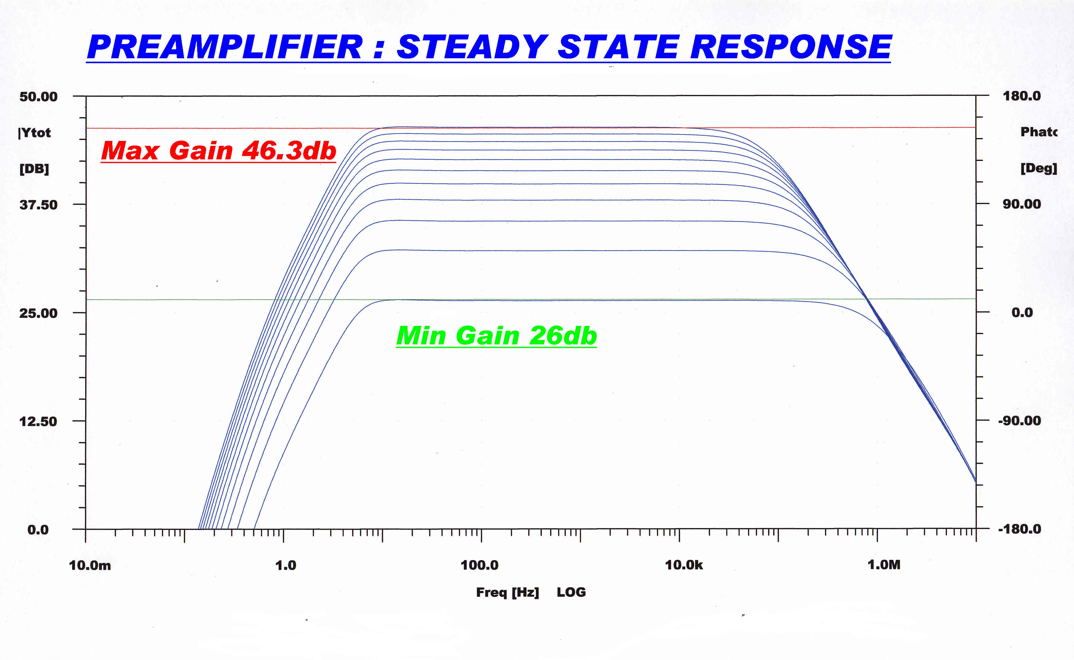 The steady state response is shown on the right.
The high frequency turn over varies from about 80KHz at maximum gain to about 1.1MHz
at minimum gain.
As pointed out above, the low frequency turnover at about 4Hz is independent of gain.
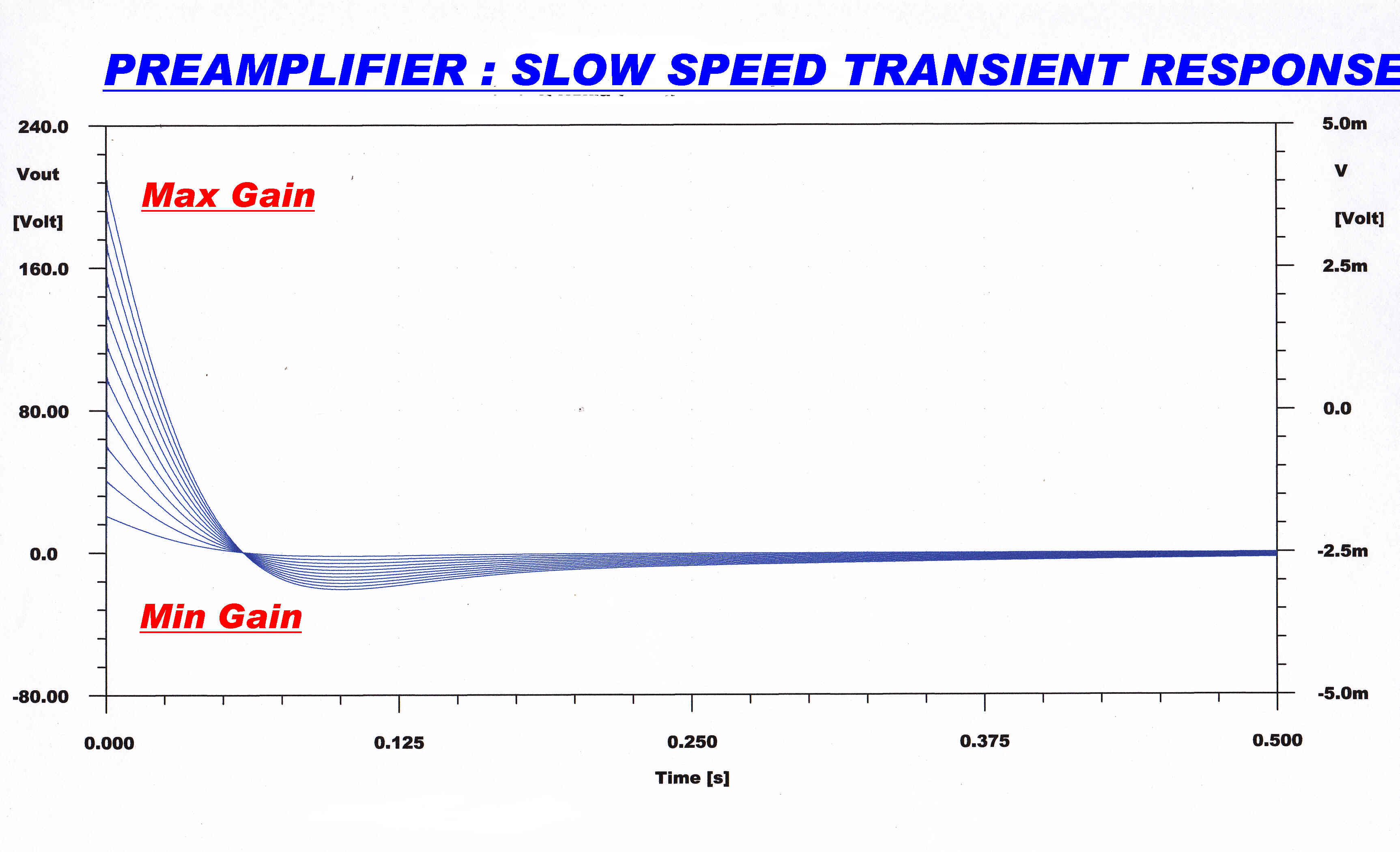
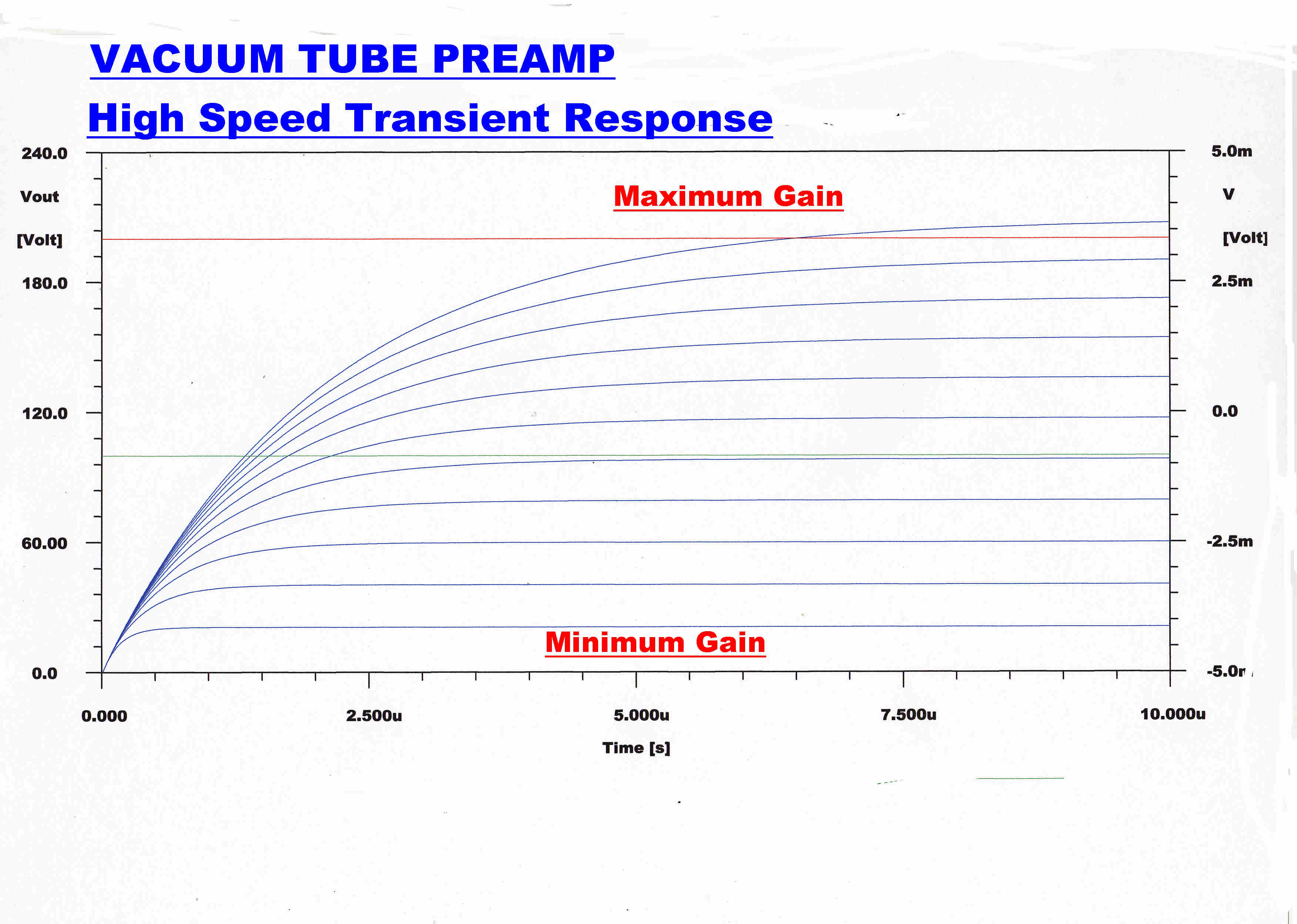
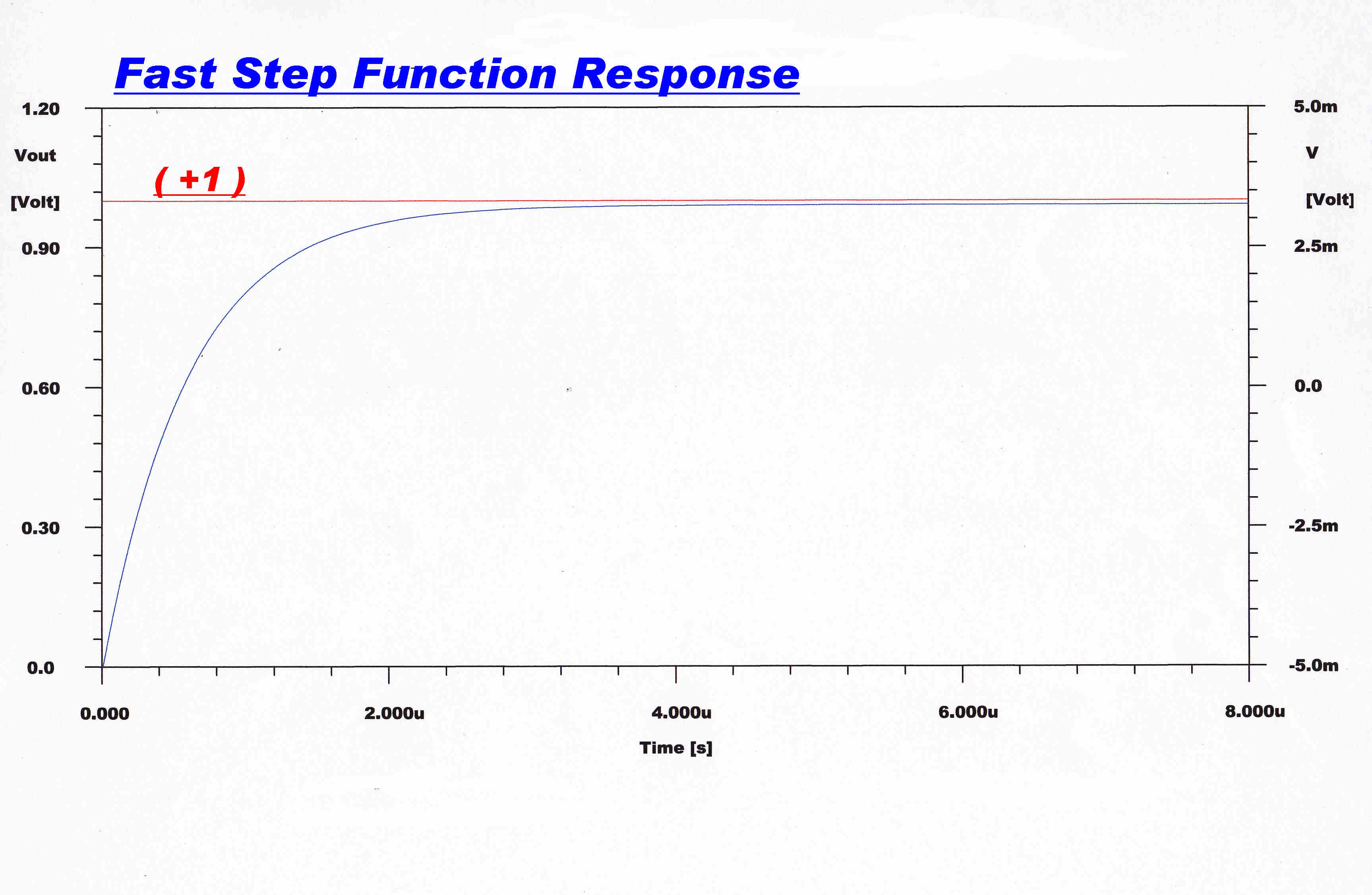
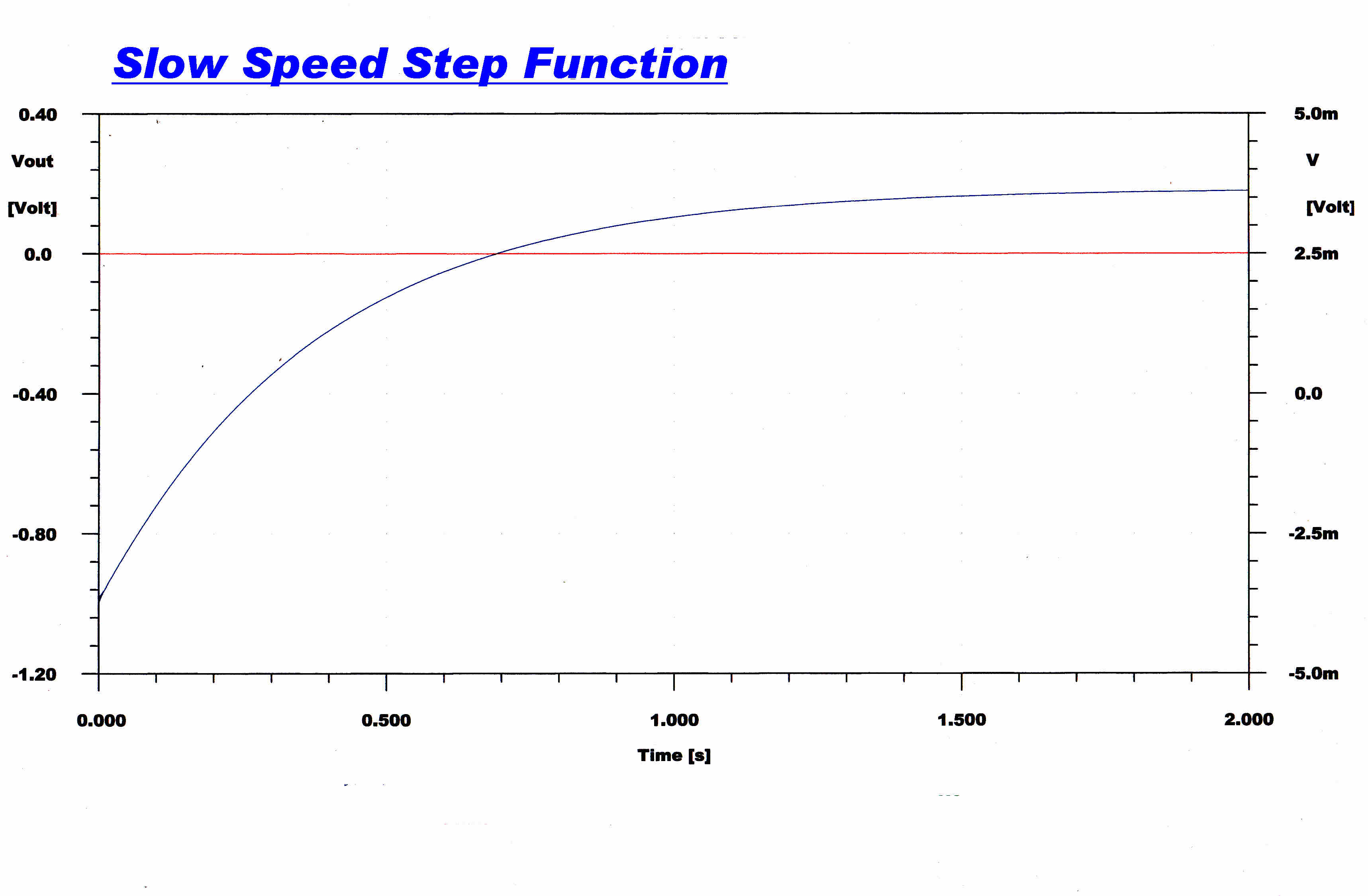
THe slow and high speed unit step function response is shown below.
|
|
|
As the amount of feedback is increased the amplitude
of the response decreases, but the waveshape stays constant. |
The high speed response is monotonic with no ringing. |
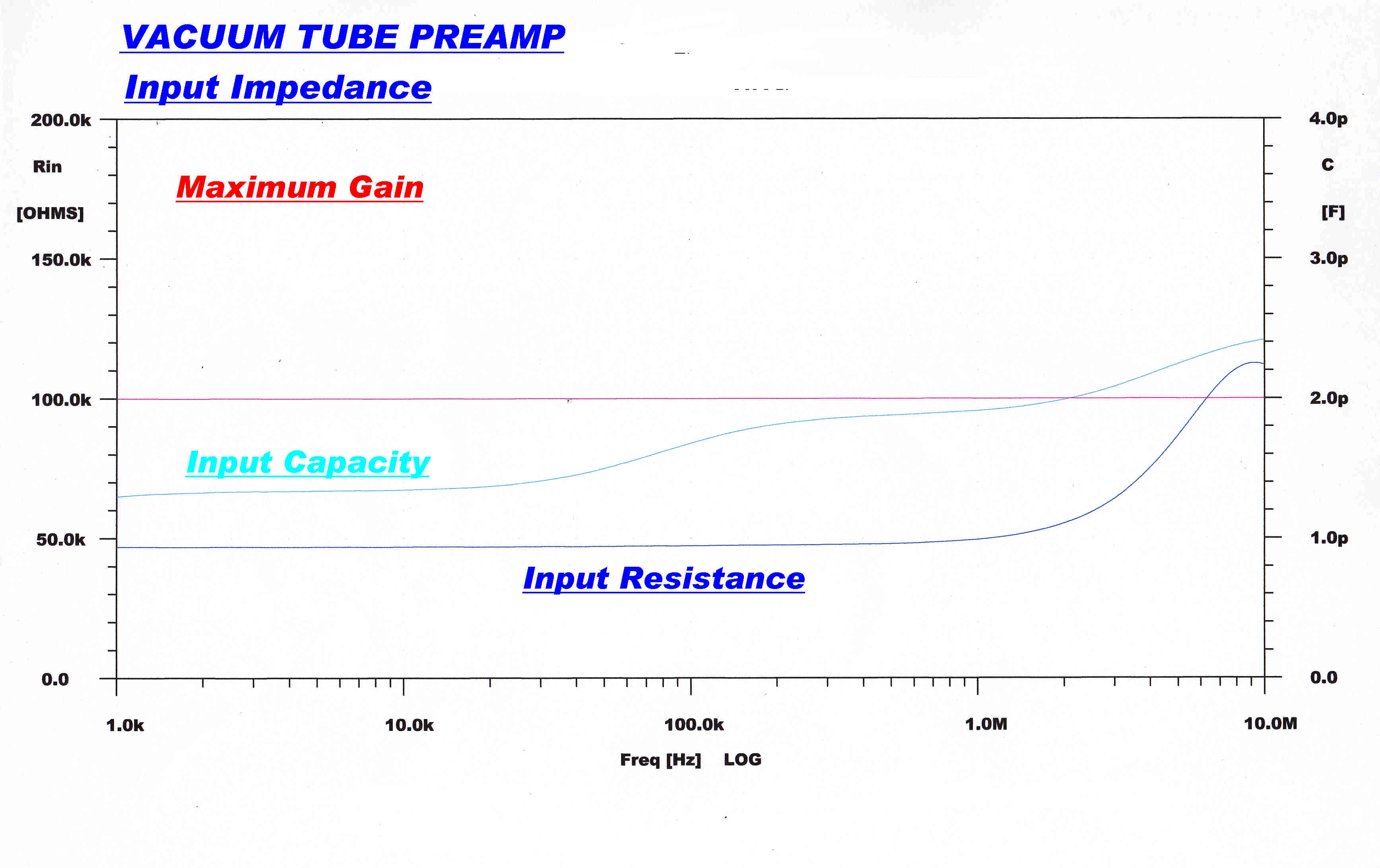
The input voltage appears between the grid of the EF86 and the cathode and screen
which are both driven by the feedback.
The input capacity of an EF86 is 3.8pF.
The feedback voltage lags the input voltage at high frequencies. The current flowing
through the input capacity therefore has an in-phase and quadrature component.
This changes the input capacity and input conductance - both of which can
be negative.
The input capacity and input resistance for minimum and maximum feedback are shown below.

|
|
|
Below 100KHz the input capacity is reduced to 0.2pF and the input resistance is unaffected at 47k. |
Below 100KHz the input capacity has risen to about 1.6pF
and the input resistance is still at 47K. |
As an example:-
For the Stanton 500MKII Cartridge :-
R = 535 ohms
L = 400mH
Rload = 47K
Cload = 275pF This is the shielded lead to the preamp.
Obviously the small variations in C noted above are of no consequence.
Data for the EF86 is shown below.
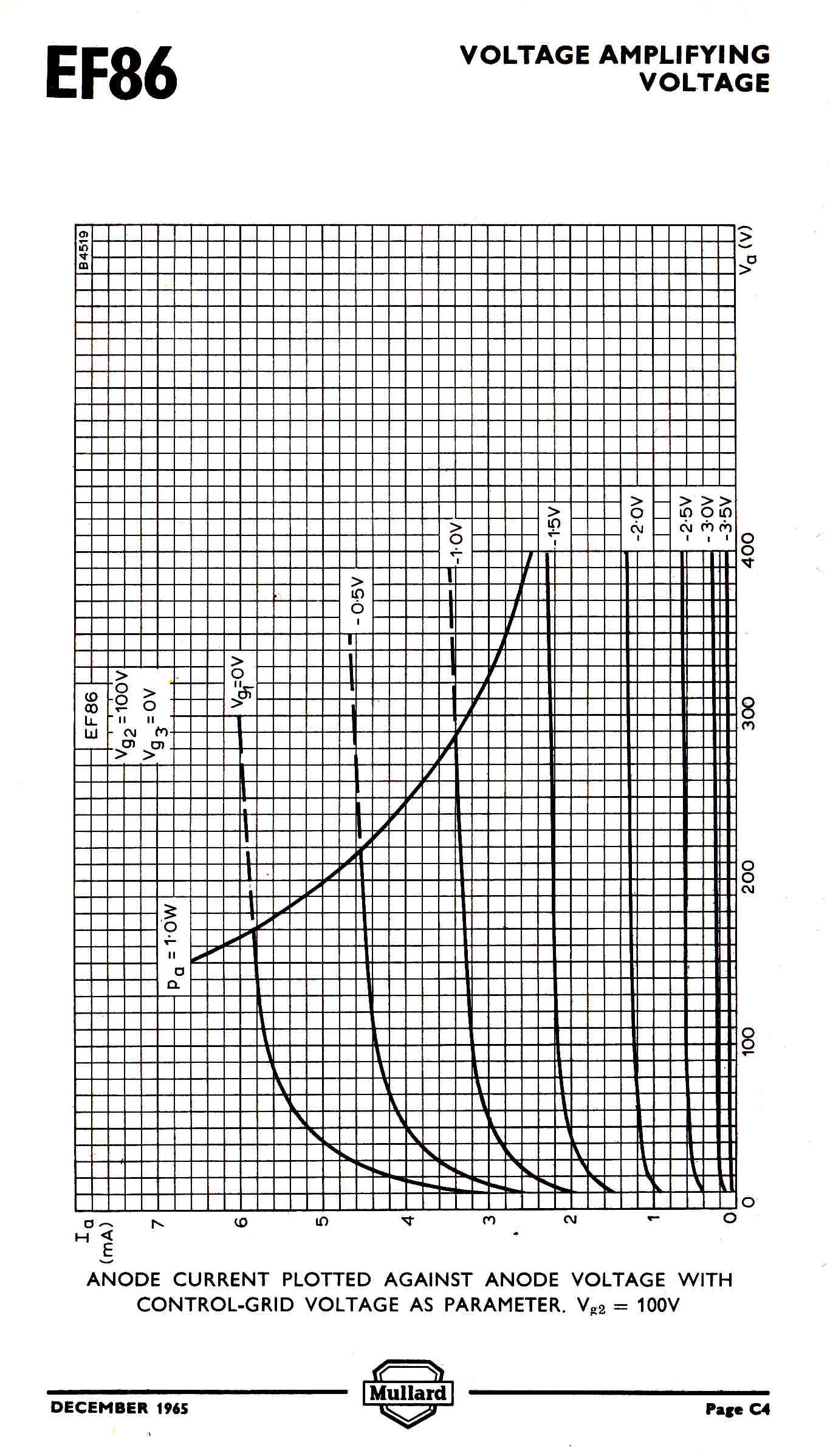
|
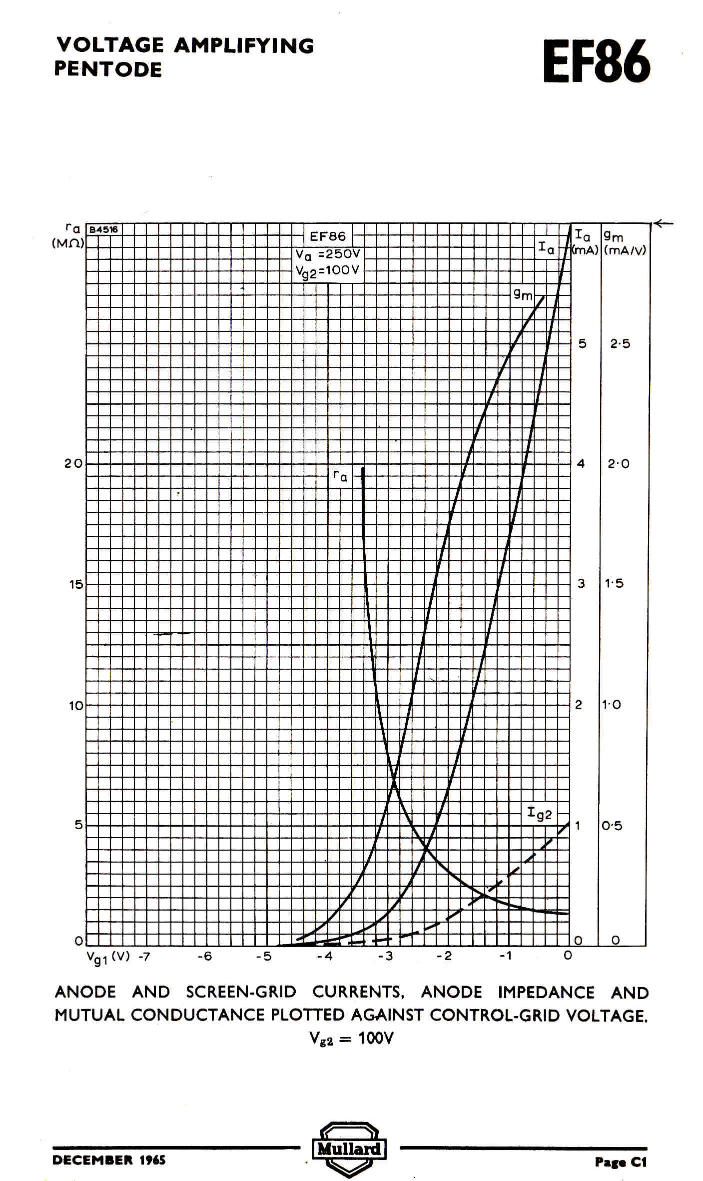
|
A horn loaded diaphragm in an acoustic reproducer requires a constant velocity drive
for a flat response.
That is, the amplitude of the displacement of the drive must be inversely
proportional to frequency or, to put it another way, the displacement of the track
cut onto the disc must be the integral of the pressure wave in the studio.
It is fortuitous that a magnetic pickup differentiates the signal and also requires
a constant velocity track for a flat response.
The constant velocity track, then, is the defacto standard in disc recording.
It comes with a blessing and a curse.
The blessing:-
A square wave input results in a triangular wave cut onto the disc.
This is negotiable by a reproducing stylus.
The curse:-
At low frequencies the track excursions become so large that they ruin the recording.
In lateral recording the track cuts into the adjoining groove, and in vertical
recording the stylus leaves the surfce of the disc.
The recording horns seen in acoustic studios often appear very small, even though a horn
with a large mouth area would capture more acoustic power.
It would appear that the smaller horns are used as high pass filters to get rid of
low frequencies which take up a lot of "room" on the track, but are not reproduced by the
relatively small reproducing horns.
Most recording horns had a cutoff frequency of about 200Hz , so the problem of
overcutting on bass did not arise. With the introduction of electrical recording, it was
desired to extend the response down to 50Hz and below.
The solution was to attenuate the bass below a given frequency by 6db/octave to give
a constant amplitude track.
The network to correct this bass attenuation on playback is called the equalisation network. Its response will fall by 6db/octave from some specified low frequency down to the turnover frequency and then remain flat.
Note: The term "equaliser" originated when radio programs were first relayed over
telephone lines.
The line was terminated in an "equaliser" which had an adjustable response at various
key frequencies within the frequency range of interest.
Sine waves of variable frequency and constant amplitude were sent over the line and the
equaliser adjusted until the outputs were all equal - hence "equaliser".
The electrically recorded Edison vertical cut Diamond Discs and 78s cut with the Harrison and Blumlein cutters
were constant amplitude up to a set turnover frequency and constant velocity above.
The turnover frequency was usually between 250Hz and 300Hz.
It was pointed out in the Harrison cutter section of the WE4A pickup, that the turnover
frequency was designed into the cutting head and set by adjusting the compliance of
the stylus centering spring.
The Edison electrical Diamond Discs have the matrix numbers: 18 - - -
Discs cut with the Harrison cutter have a triangle or a W in a circle after the matrix
number.
Discs cut with the Blumlein moving coil cutter have a square after the matrix number.
PREEMPHASIS
In the late thirties or early forties PREEMPHASIS was introduced
to disc recording.
Above a set frequency ( usuallly 2 or 3 KHz ) the high frequencies were boosted.
The high frequency attenuation network to obtain a flat response on replay was added
to the disc equaliser and the process called DEEMPHASIS.
This was an attempt to reduce surface noise : for the high frequency attenuation also
attenuated the noise.
Tracks cut with preemphasis approximate constant amplitude, so that it greatly increases
the tracing distortion and pinch effect.
I have always found tracing distortion far more objectionable than surface noise, so
believe preemphasis was a bad mistake.
Preemphasis was introduced in the USA : fortunately British and European discs escaped
the curse.
The use of preemphasis may have been inspired by FM which was introduced about the
same time.
It seems to be a well kept secret that FM is subject to "blue" noise, and preemphasis
was introduced to mask it. ( See discussion of FM in the INTRODUCTION )
In an electrical reproducer with appropriate equalisation, preemphasis increases
tracing distortion and pinch effect.
The effect on acoustic reproducers with no equalisation is catastrophic -
the reproduction is shrill and distorted.
The early discs recorded with preemphasis had a turnover frequency of 500Hz which
doubled the recorded velocity and made matters even worse.
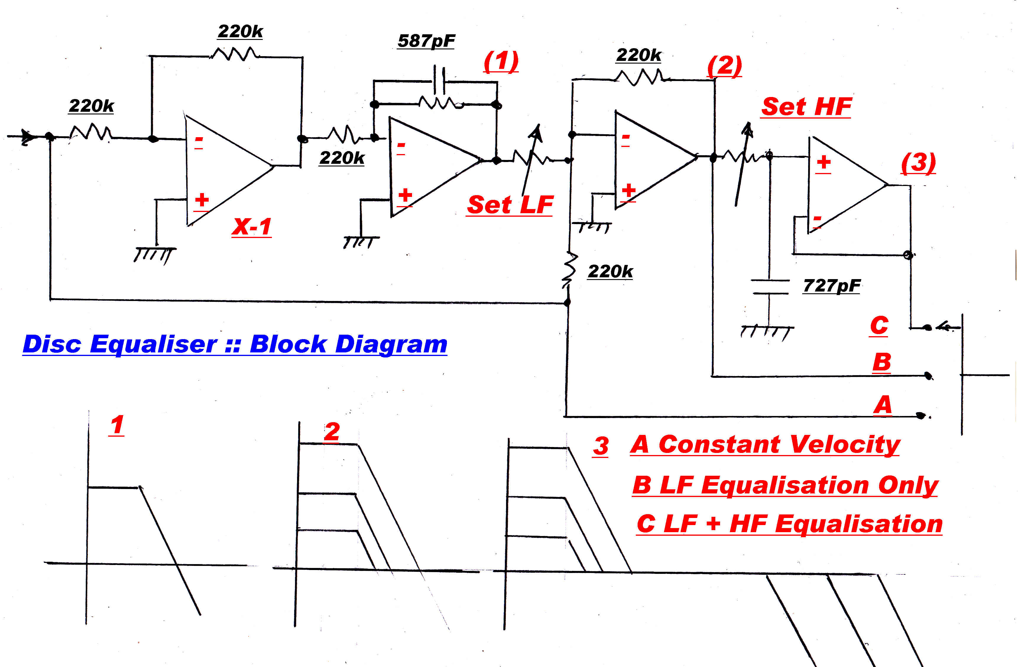 The block diagram for the disc equaliser is shown on the right.
(A)The magnetic pickup differentiates the track on the disc, and so has a constant
velocity response.
The preamplifier has a flat response, so in position A the overall response
is also constant velocity.
All acoustically recorded discs require constant velocity playback.
(B) The first two stages are flat up to some low frequency ( say 10Hz ) and then
produce a response which falls off at 6db/ octave.
This is added to the original signal through a variable resistor ( set LF)
to give the response shown in (2).
The transition frequency to constant velocity is controlled by the value
of the resistor.
Two fixed resistors give standard turnover frequencies of 250Hz and 500Hz and
a variable resistor varies the turnover from 150Hz to 750Hz.
Most of the 78s recorded in Europe through to the forties can be equalised with
this curve. Discs recorded in the US with the WE cutter are also covered.
It often happens that the turnover frequency is not known and is set by ear.
(C) An R-C network having a slope of 6db/octave is placed in the signal path to
remove preemphasis.
A few of the problems in reproducing from Vertical and Lateral
cut tracks with a modern stereo pickup.
It would seem that Edison got everything right in his original
proposal for recording:-
(1) STYLUS FIT :: TRACING DISTORTION
In Edison vertically cut recordings, the cutter and reproducer stylus
are arcs of circles.
The reproducing stylus sits at the bottom of the groove, so there is
no such thing as stylus to groove fit.
This has to be so, since the groove can disappear at peak level.
Edison knew about tracing distortion and reduced the diameter of the spherical
reproducing stylus as far as possible consistent with pressure induced by the
acoustic reproducer. [ For Diamond Discs - cutter 10.5 thou - for reproducer
7 thou. ] See section on Acoustic and Early Electrical Recorders.
The weight and low mechanical input impedance of a modern stereo pickup
can easily be supported by a one thou spherical stylus, which virtually eliminates
tracing distortion, even in the inner grooves.
The behaviour of the reproducing stylus is different when traversing a "Hill"
and a "Valley", so the tracing distortion in a vertical cut disc
is asymmetrical.
It therefore contains even harmonics.
The tracing distortion in a lateral is symmetrical and so contains
only odd harmonics.
This fact surfaced in a detailed analysis and gave rise to the conclusion that
lateral modulation was superior to vertical.
It seems to me that modern lightweight high compiance pickups have
invalidated that conclusion.
While an elliptical stylus can reduce tracing distortion in lateral discs, the
vertical discs played wity a low diameter spherical stylus offer a far more
satisfactory solution.
A detailed analysis of tracing distortion was given in:-
W D Lewis and F V Hunt : A Theory of Tracing Distortion in
Sound Reproduction from Phonograph Records.
J of AM ACOUS SOCIETY pp 348 - 365 1941
(2) TRACKING ANGLE
The movement of the cutting stylus in vertical recording is at right angles to the record surface,
so the reproducing stylus should be constrained to move at right angles to
the surface otherwise distortion occurs.
See the section on "SCANNING DISTORTION" in the Edison section.
Most stereo pickups track about 15 to 20 degrees away from the vertical.
Fortunately, the Edison discs are recorded at a much lower level than
the lateral discs and this greatly reduces the distortion.
In laterals the maximum amplitide is about +(-)2 thou. : in Edisons +(-)0.9thou.
Edison discs are about 0.25 inches thick. This raises the cartridge and lowers
the built in vertical tracking angle.
For cartridges suspended on an arm, there is no channge in the vertical
tracking angle across the disc.There is always a change, and hence an error, in
the lateral tracking angle.
 Pinch effect causes distortion and wear in lateral cut discs.
It does not exist in vertical cut discs.
Pinch effect causes distortion and wear in lateral cut discs.
It does not exist in vertical cut discs.
The cutting stylus has a flat face. When it moves at right angles to
the direction of groove travel in lateral recording the width of the
groove decreases and a reproducing stylus rises, so that it has a vertical
component. This is true for both directions of movement of the recording stylus,
so the vertical movement has twice the frequency of the recorded signal - the
distortion is even.
Lateral pickups should:-
(a) Be unresponsive to vertical movement
(b) Have a very high vertical compliance, so the stylus can follow the
vertial movement.
The magnitude of the pinch effect:-
SINUSOIDAL SIGNAL
Let a sinusoid of peak deviation d be laterally cut on a disc with
angular frequency ω
Then the track deviation x is described by:-
x = d sin( ω t )
v = dx/dt = ω d cos( ω t ) where v is the track velocity
V = ω d = 2 π f d where V is the maximum velocity;
f is the frequency.
The groove velocity vg = 2 π r c : r is the radius
of the track and c is the rotational velocity in revs/sec
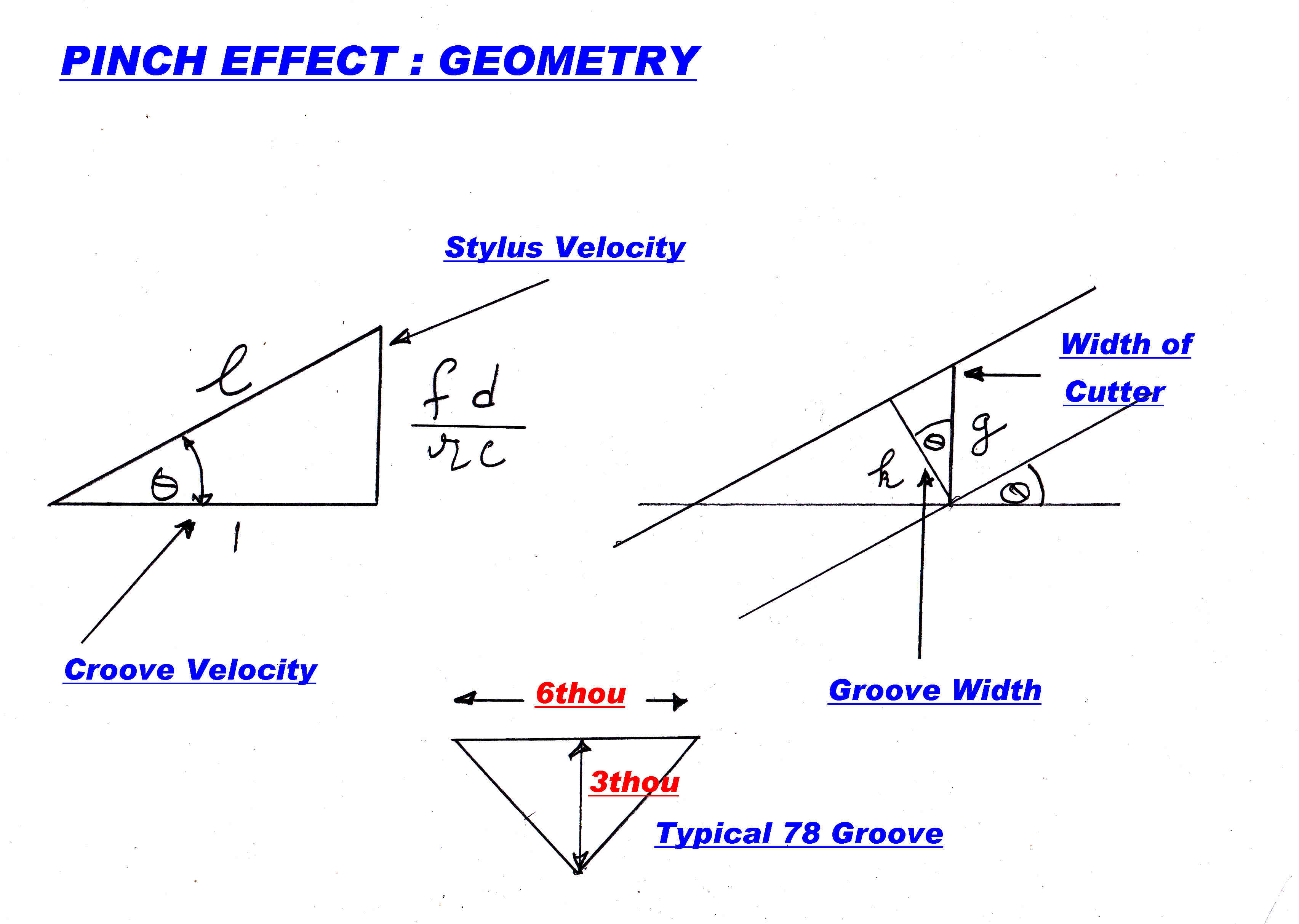
The track deviates by an angle θ :-
θ = tan-1( V/vg )
= tan-1( 2πfd/2πrc )
= tan-1( fd/rc )
From the geometry shown in the diagram the track width is reduced
by the factor cos( θ ) where :-
cos( θ ) = 1/[ 1 + ( fd/rc )2 ]1/2
If D is the depth of cut, then it is reasonable to assume that the peak
to peak vertical movement p is given by:-
p = D { 1 - 1/[ 1 + ( fd/rc )2 ]1/2 }
LOW FREQUENCY SQUARE WAVE
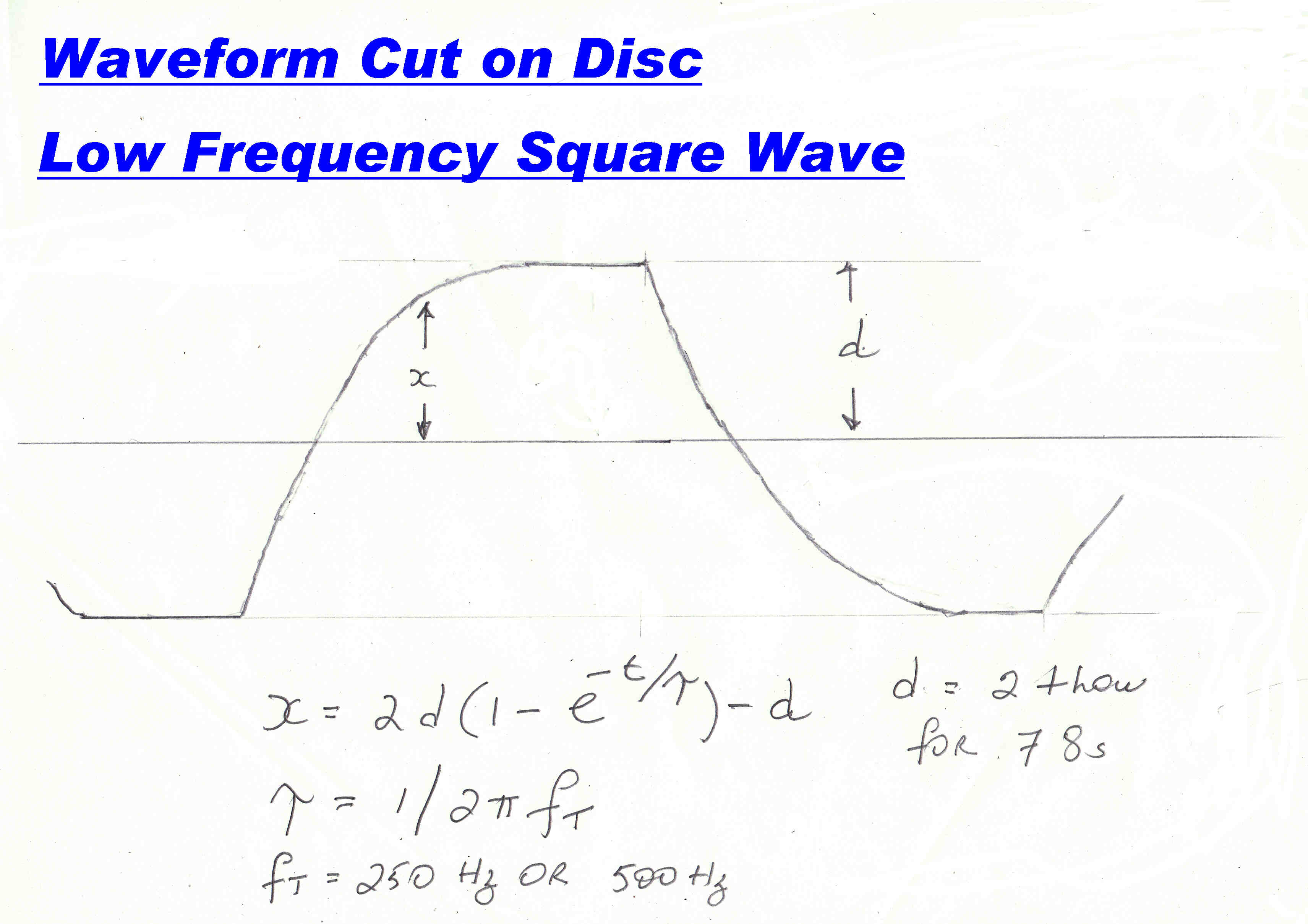 Suppose a high amplitude low frequency square wave
(say 20Hz) is applied to the recorder.
Suppose a high amplitude low frequency square wave
(say 20Hz) is applied to the recorder.
In terms of stylus displacement, the system is flat up to the turnover
frequency fc and then the response falls off at 6db/octave.
The transient response of this system is given by:-
x = 2d( 1 - e-t/τ ) - d : where τ = 1/2πfc
The stylus velocity v is given by:-
v = dx/dt = ( 2d/τ ) e-t/τ
The maximum velocity V occurs at t = 0 so;-
V = 4πdfc
The maximum track deviation angle θ is given by:-
θ = tan-1( 2dfc/rc ) and :-
cos( θ ) = 1/[ 1 + (2fcd/rc )2 ] 1/2
And from above:-
p = D { 1 - 1/[ 1 + ( 2fcd/rc )2 ]1/2 }
It is interesting to put some numerical values into these equations:-
For worst case conditions assume a recording radius r of 2 inches :
a groove deviation d of 2thou.: and a groove depth D of 3thou.
in a 78 rpm recording.
r = 2: d = 2 x 10⁻³ : D = 3 x 10⁻³ : c = 78/60 rps
For a sinusoidal track we get:-
Turnover frequency 250Hz : θ = 10.9deg : p = 5.4 x 10 -2 thou.
Turnover frequency 500Hz : θ = 21deg : p = 0.2 thou.
For a square wave track we get:-
Turnover frequency 250Hz : θ = 21deg : p = 0.2 thou.
Turnover frequency 500Hz : θ = 37.6deg : p = 0.622 thou.
These are not insignificant amounts of distortion.
If a lateral monophonic disc is played in the stereo position, this distortion
will appear in both channels with little hope of cancellation.
Mono lateral discs should be played with a pickup unresponse to vertical movement.
In setting up for mono lateral reproduction, the channels are first
subtracted and the relative gains slowly changed. The main signal can be heard
in the background of pinch effect distortion. Set the relative gains to reduce
the main signal to a minimum and then switch to add the signals.
For Edison Hill and Dales initially add the channels and adjust for minimum signal :
there is no pinch effect distortion to confuse the issue.
Pinch effect and tracing distortion are always present
on a stereo disc.
A vertically cut mono recording eliminates most of the problems. There
is a small minority, like myself, who consider stereo on disc a bit of a
disaster, and would prefer a low distortion mono vertically cut track.
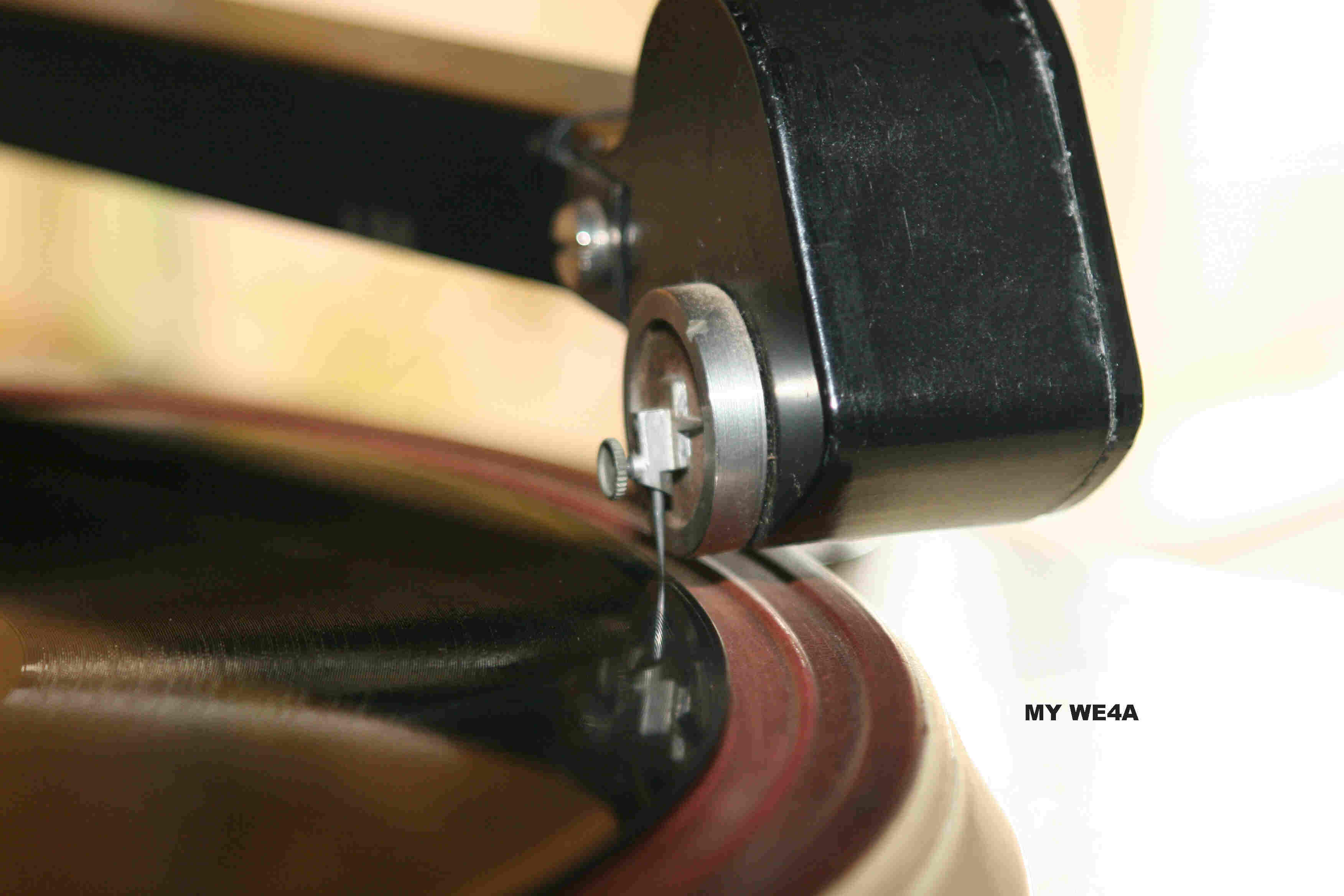 The early acoustic and electrical pickups had virtually no vertical
compliance, and made no allowance for pinch effect in lateral recordings.
The early acoustic and electrical pickups had virtually no vertical
compliance, and made no allowance for pinch effect in lateral recordings.
The Western Electric WE4A shown opposite is a good example.
This pickup was used by the Australian National Broadcaster, the ABC, up until at least
the mid forties.
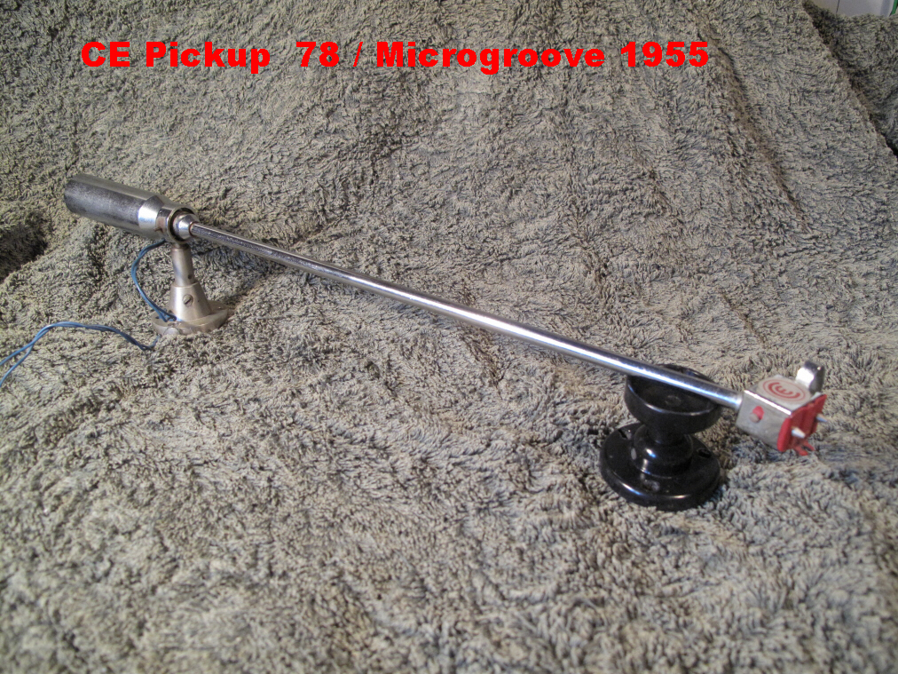
Microgroove was introduced in the early fifties, and pickups were designed
to play both systems.
An ingenious Australian design for ease of stylus change during
the course of a broadcast is shown below.
The pickup has a high vertical compliance and is responsive to lateral modulation only.
The pickup is shown in detail below:-
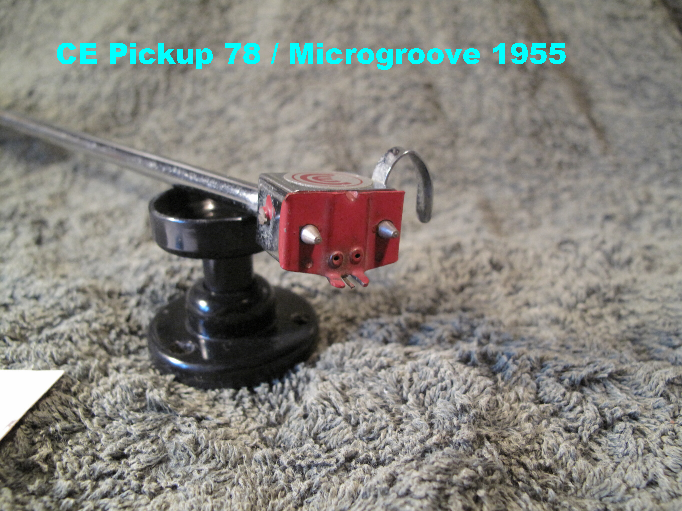
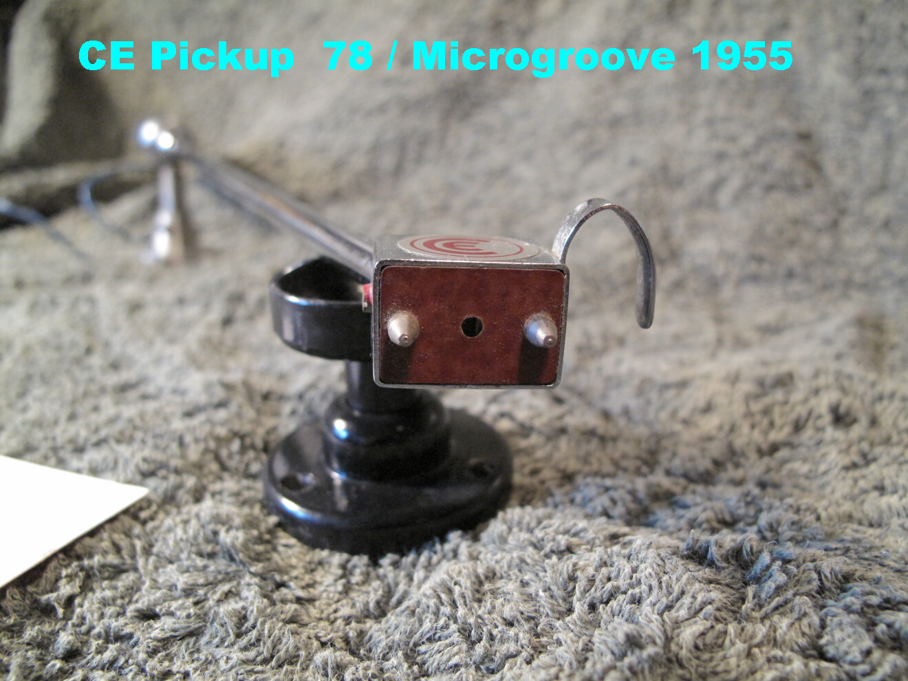
PICKUP DETAILS
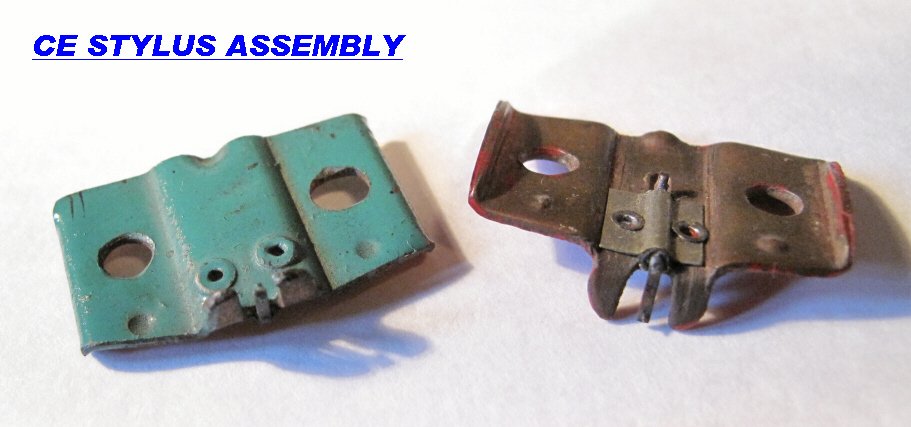
The stylus plate is part of the magnetic circuit and held in place by magnetic forces.
The stylus is mounted on the end of a cantilever with high vertical compliance and smaller
lateral compliance.
Lateral motion rotates a vertical soft iron shaft set in neoprene. The end of this shaft is
bent over to form an armature at right angles to the field in the gap of a magnetic circuit.
The neoprene forms the centering spring with viscous damping.
The neoprene spring also sets the lateral compliance at the stylus, since the lateral
compliance of the cantilaver is low.
The cantilever is 0.162 inches long. The maximum deviation on a disc is +(-) 2 thou..
If θ is the angle of deflection:-
then θmax = sin-1(2/162) = 0.707 deg.
The distortion is negligible for here we can put θ = sinθ
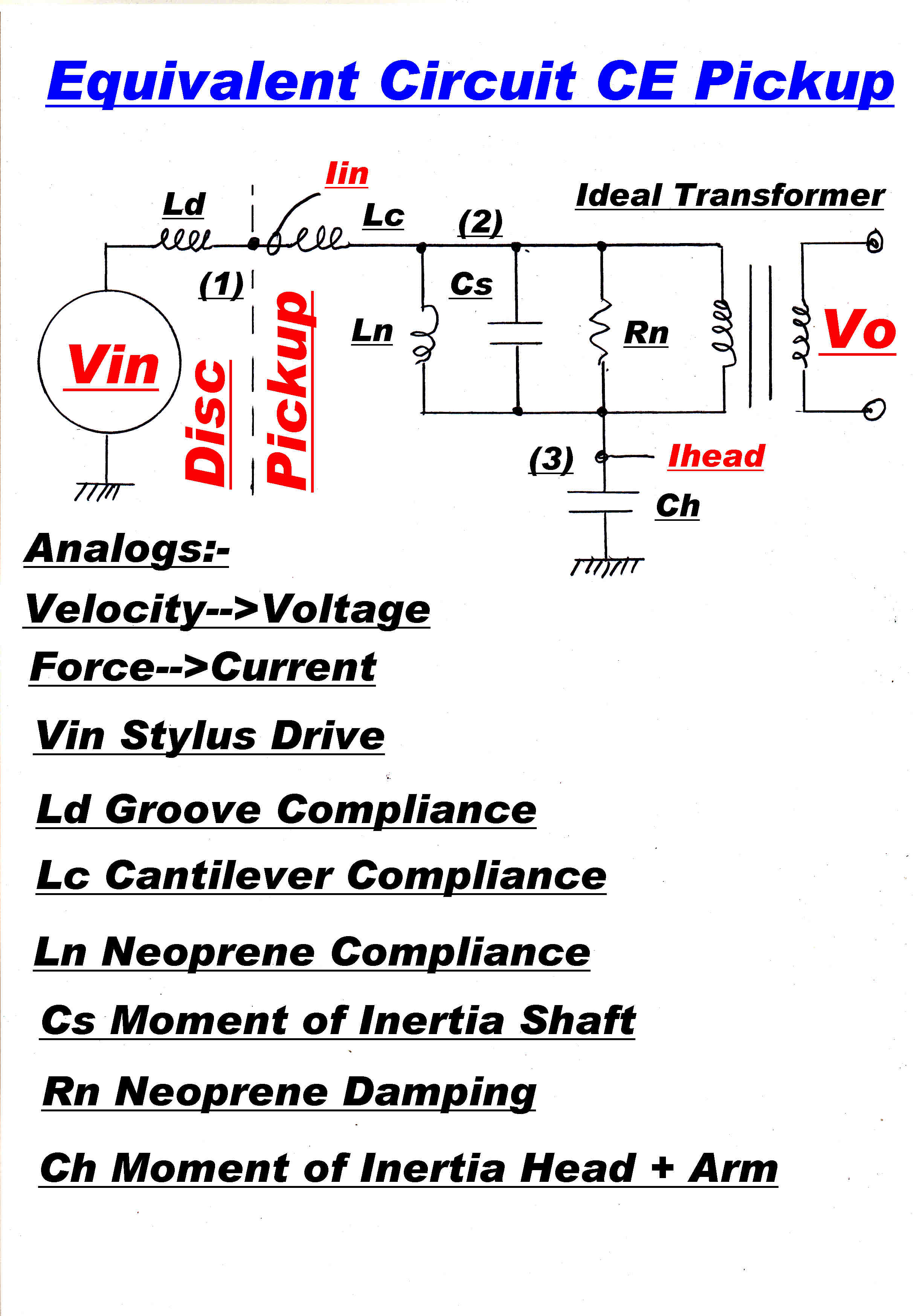
|

|
|
The equivalent circuit to analyse the dynamic behaviour of the pickup. |
The original data sheet which came with the pickup is shown above. |
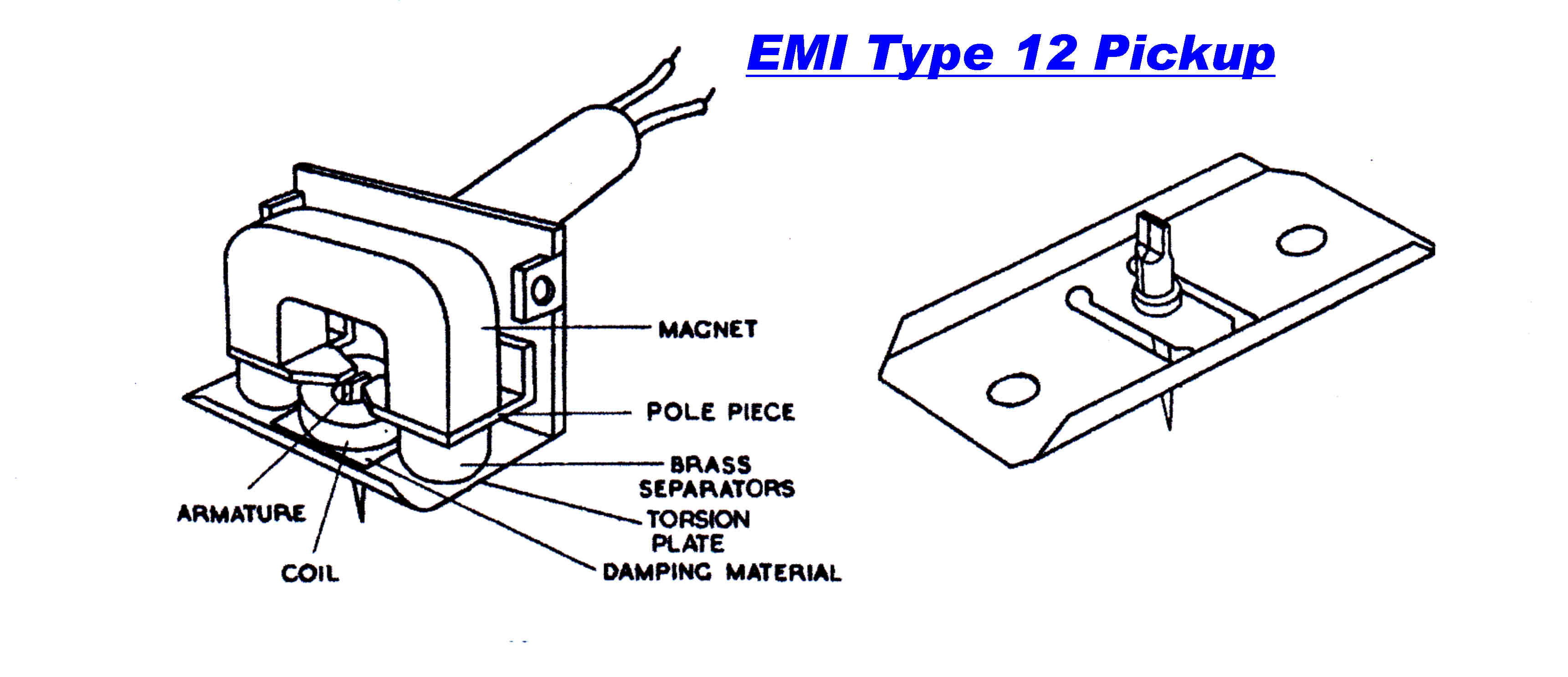 I have long suspected, but have never been able to prove, that the EMI-12
pickup was the basis for the design for the CE pickup.
I have long suspected, but have never been able to prove, that the EMI-12
pickup was the basis for the design for the CE pickup.
I first saw the EMI-12 pickups in use at a Brisbane commercial radio
station 4BK in 1948.
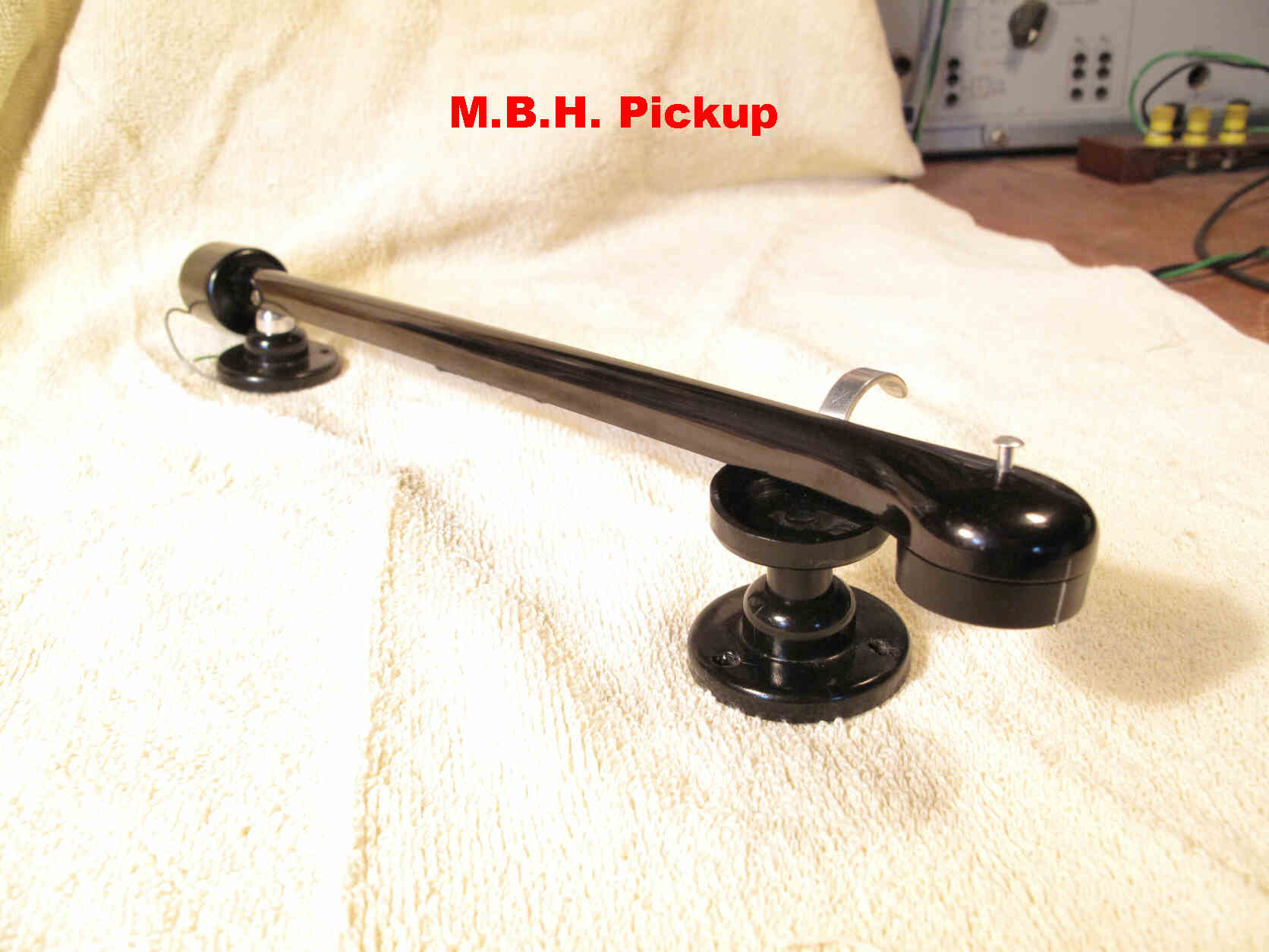
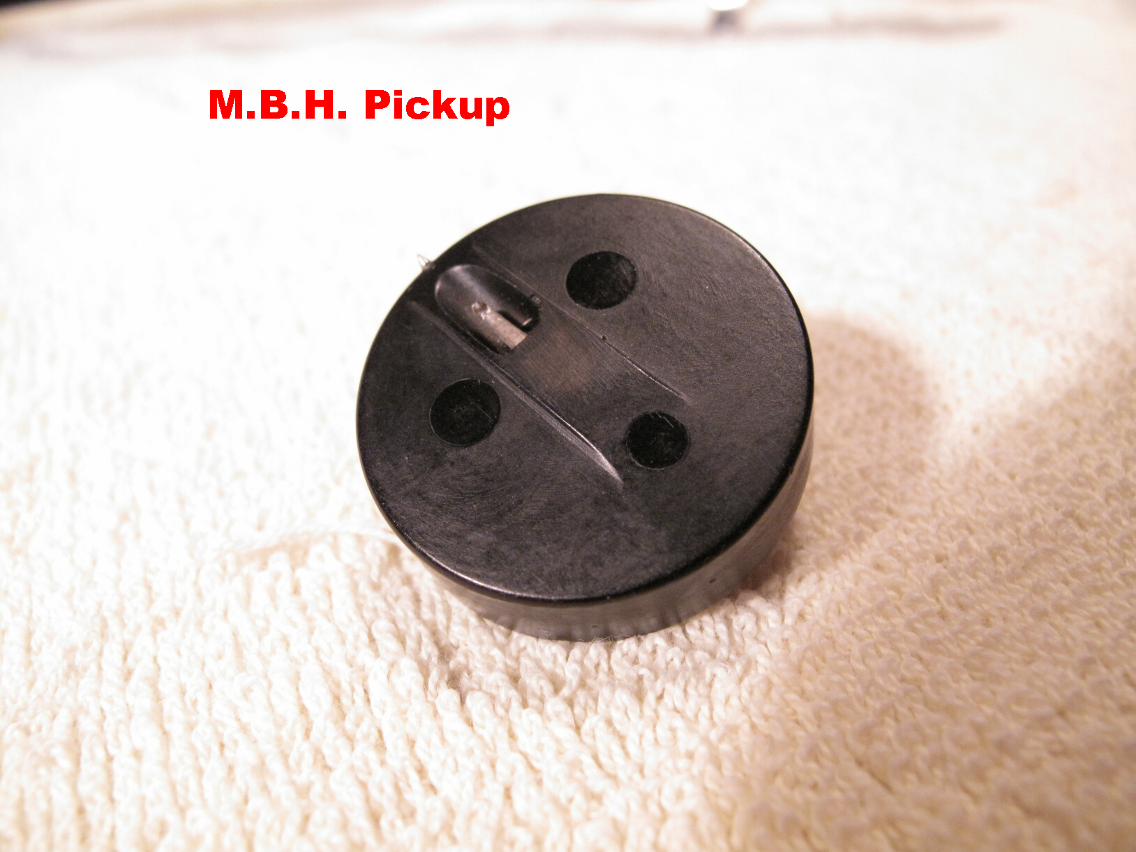
For comparison a competing Australian designed pickup - The MBH -
is shown below.
The mass of the stylus assembly was large in the early models. This produced large
inertial forces in the vertical direction due to pinch effect.
Later models used a cantilever design to overcome this.
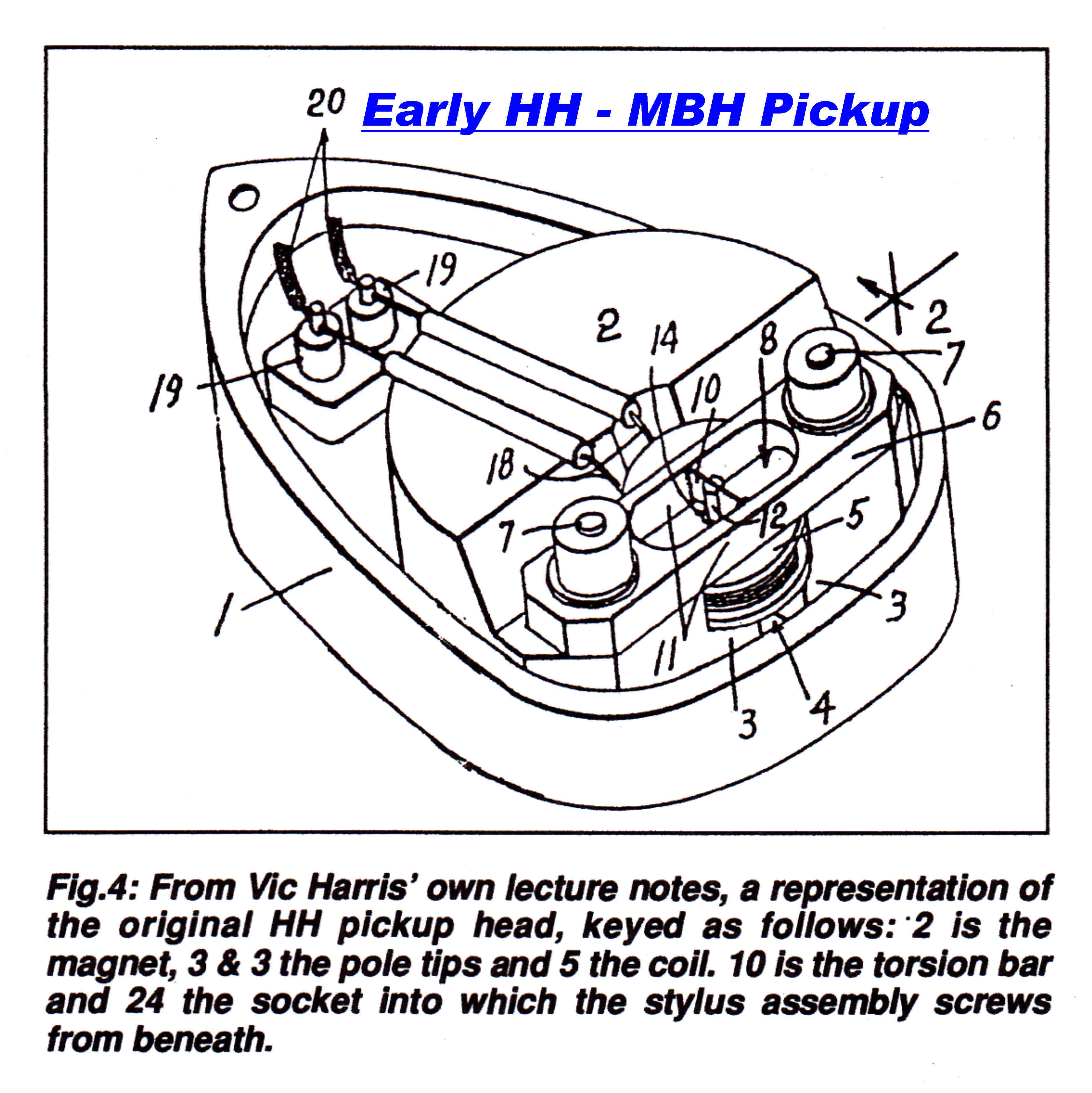 An early version of the HH - MBH pickup.
This diagram was copied from an article by Neville Williams on the life of
Victor Harris.
Electronics Australia October 1995.
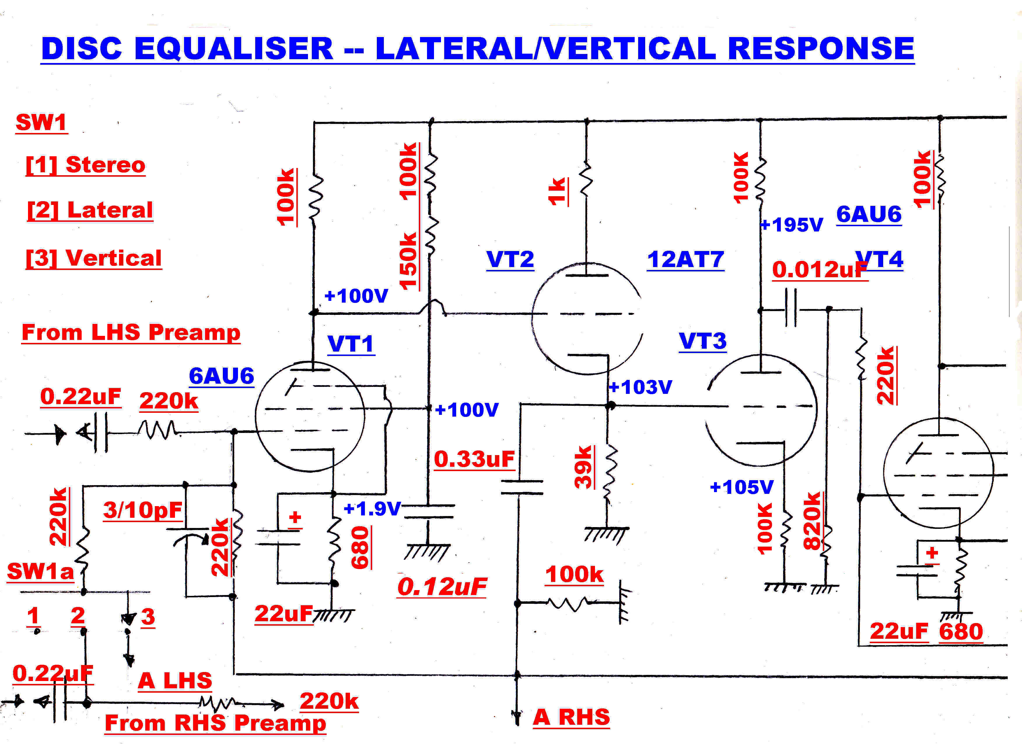
The complete circuit of the disc equaliser is shown below:
|
|
|

The switch functions are shown on the right.
 The amplifier shown on the right is the basic building block of the equaliser.
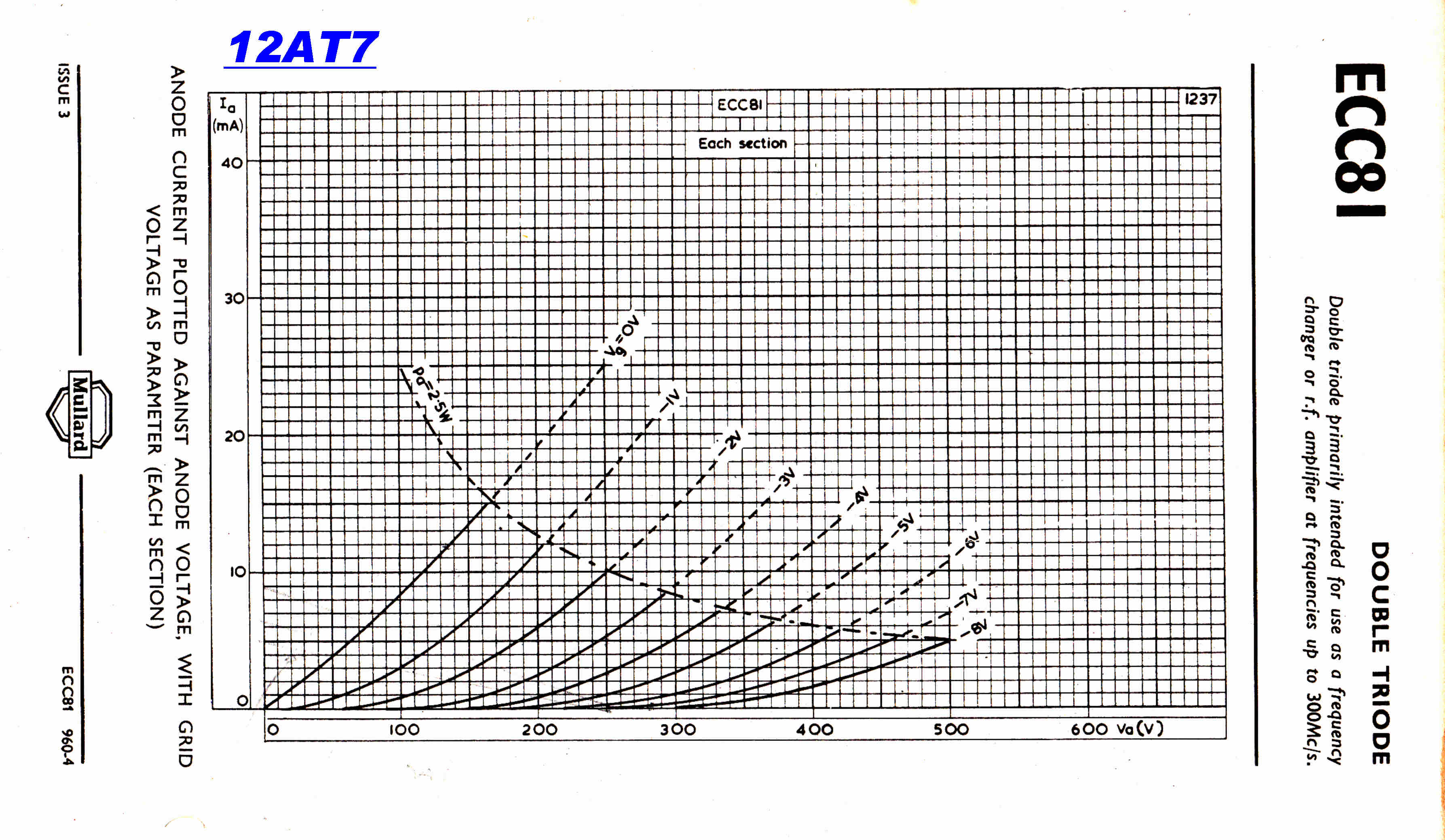
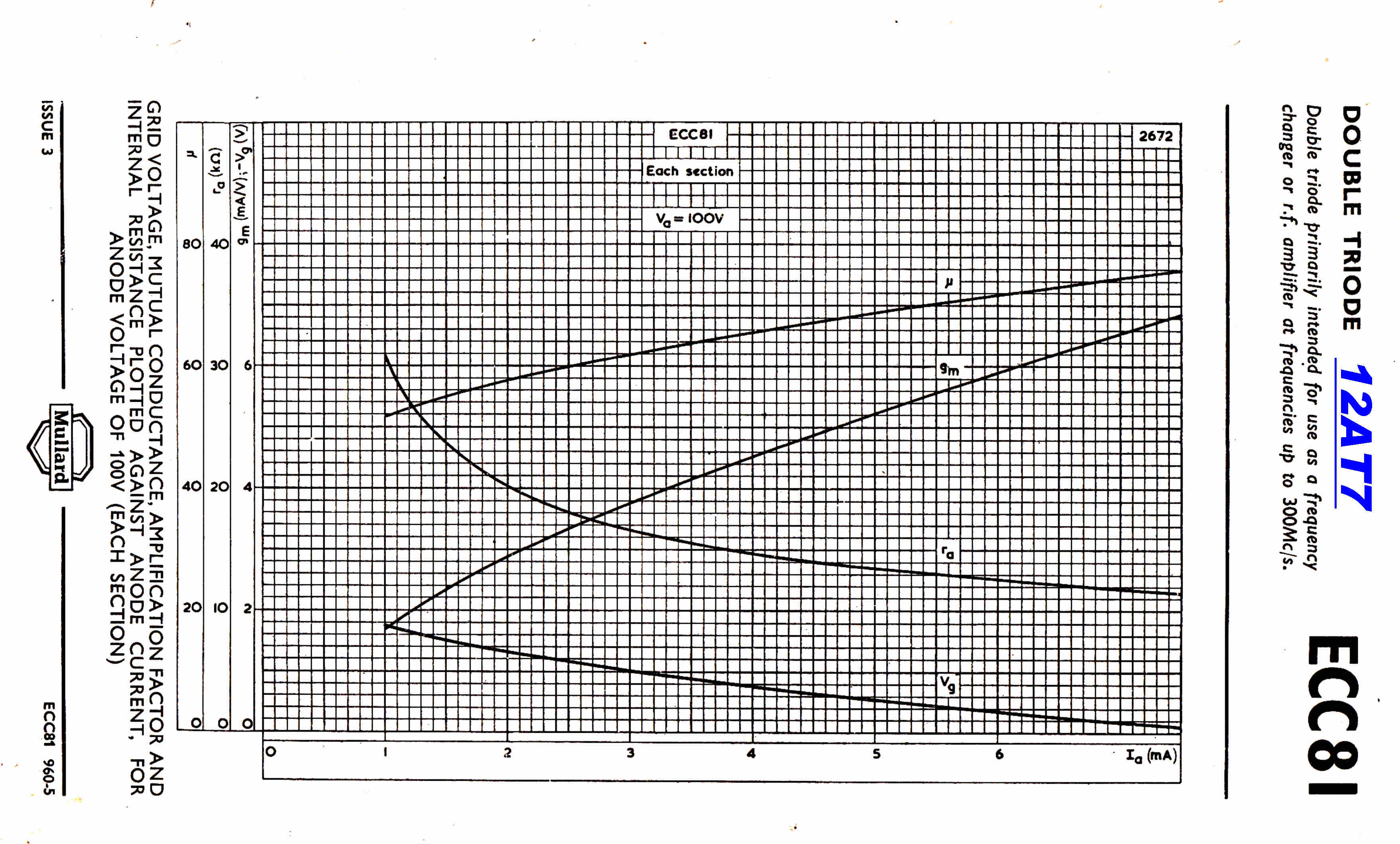
It consists of a pentode voltage amplifier - 6AU6 - followed by a triode
cathode follower - 12AT7.
The amplifier is used as a summing amplifier with a large degree of feedback.
The cathode follower and high voltage feedback produce a low output impedance.
The feedback also makes the amplifier immune from transients on the
high tension line which is supplied from the high performance regulator.
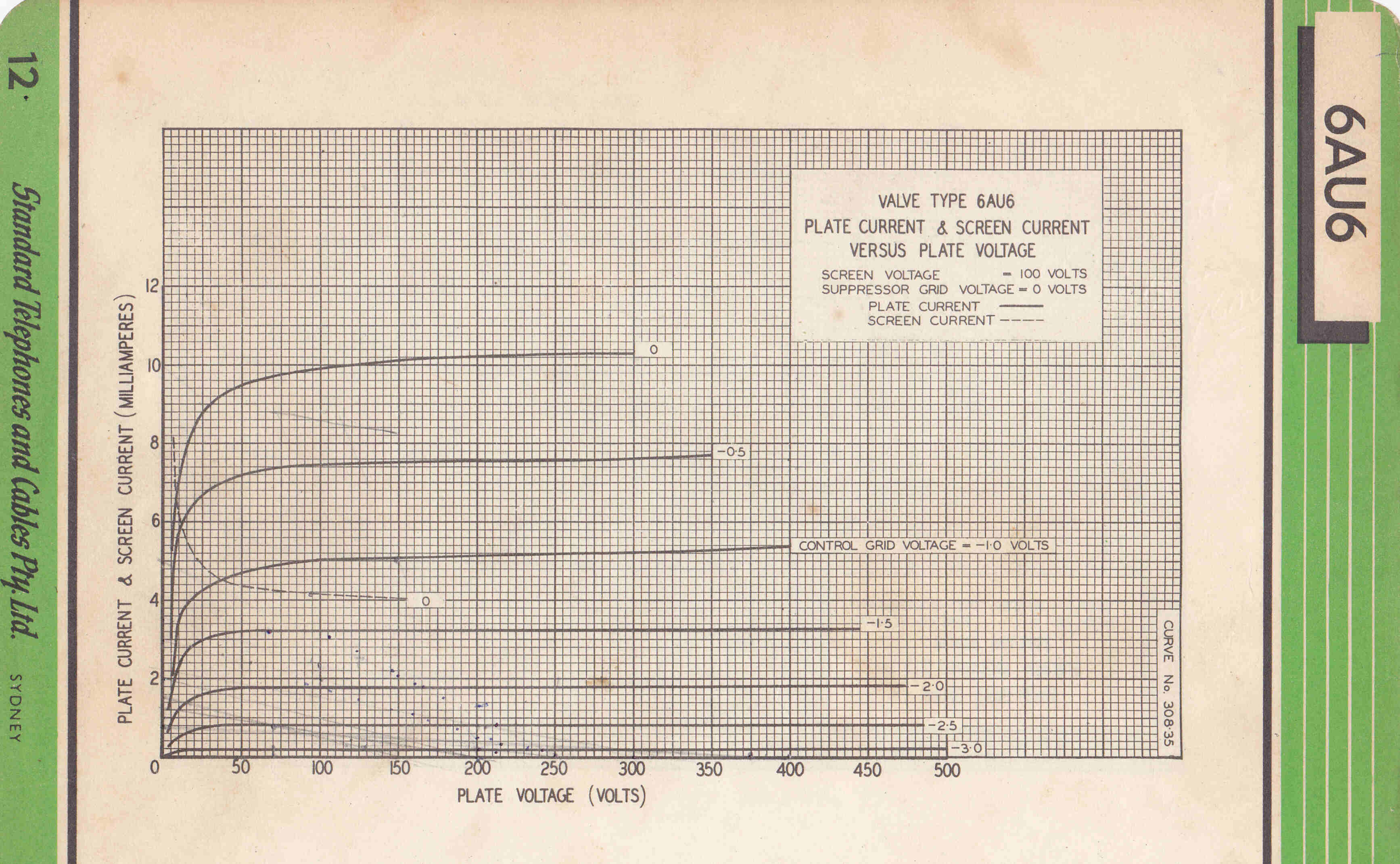
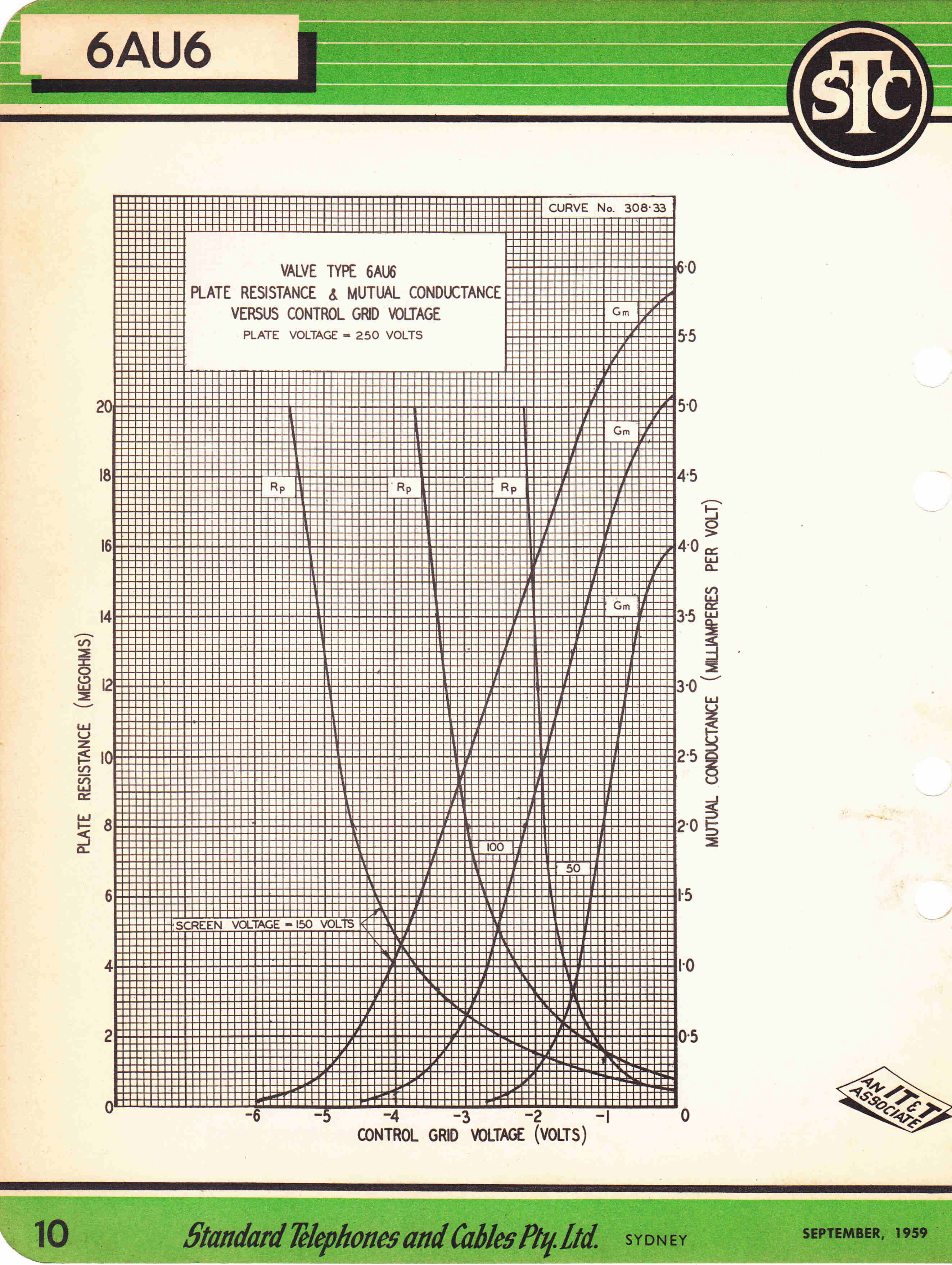
Appropriate tube data and operating conditions are given below.
|
|
|
|
|
For the 6AU6: |
For the 12AT7: |
There are potentially three poles on the negative real
axis in the high frequency feedback loop.
(1) A pole formed by the output resistance from the pentode plate R|| ( 90.91k ), the 6AU6
output capacity (5pF), the 12AT7 cathode follower input capacity (2pF)
and the stray capacity (3pF).
The turnover frequency f1 for this pole is given by :
f1 = 1/( 2 π R||Ctot ) = 175.1KHz.
(2) A pole formed by the cathode follower output resistance Rout (425.6ohms)
and the total stray C on the cathode follower output Ctot (10pF).
The turnover frequency f2 for this pole is given by :
f2 = 1/( 2 π Rout Ctot ) = 37.4MHz
(3) A pole formed by the output resistance Rd of the 220K input divider (110K)
and the input capacity Cin of the 6AU6 (5.5pF).
The turnover frequency f3 for this pole is given by :
f3 = 1/( 2 π Rd Cin ) = 263KHz.
Pole 2 is far higher than 1 and 3, so will not cause trouble under feedback.
Pole 3 is close to pole 1 and will give rise to a peak in the steady state
response and ringing in the transient response under feedback.
Pole 3 can be removed by shunting R2 with C1 to give a compensated divider.
The small capacity added to the cathode follower output reduces f2 slightly
- a small price to pay for the disappearance of pole 3.
Note: In the final design the divider is undercompensated for best overall response.
 The low frequency open loop response is dominated by the output
coupling capacitor C4. It produces a single order transfer function with
a turnover frequency at about 59Hz.
The low frequency open loop response is dominated by the output
coupling capacitor C4. It produces a single order transfer function with
a turnover frequency at about 59Hz.
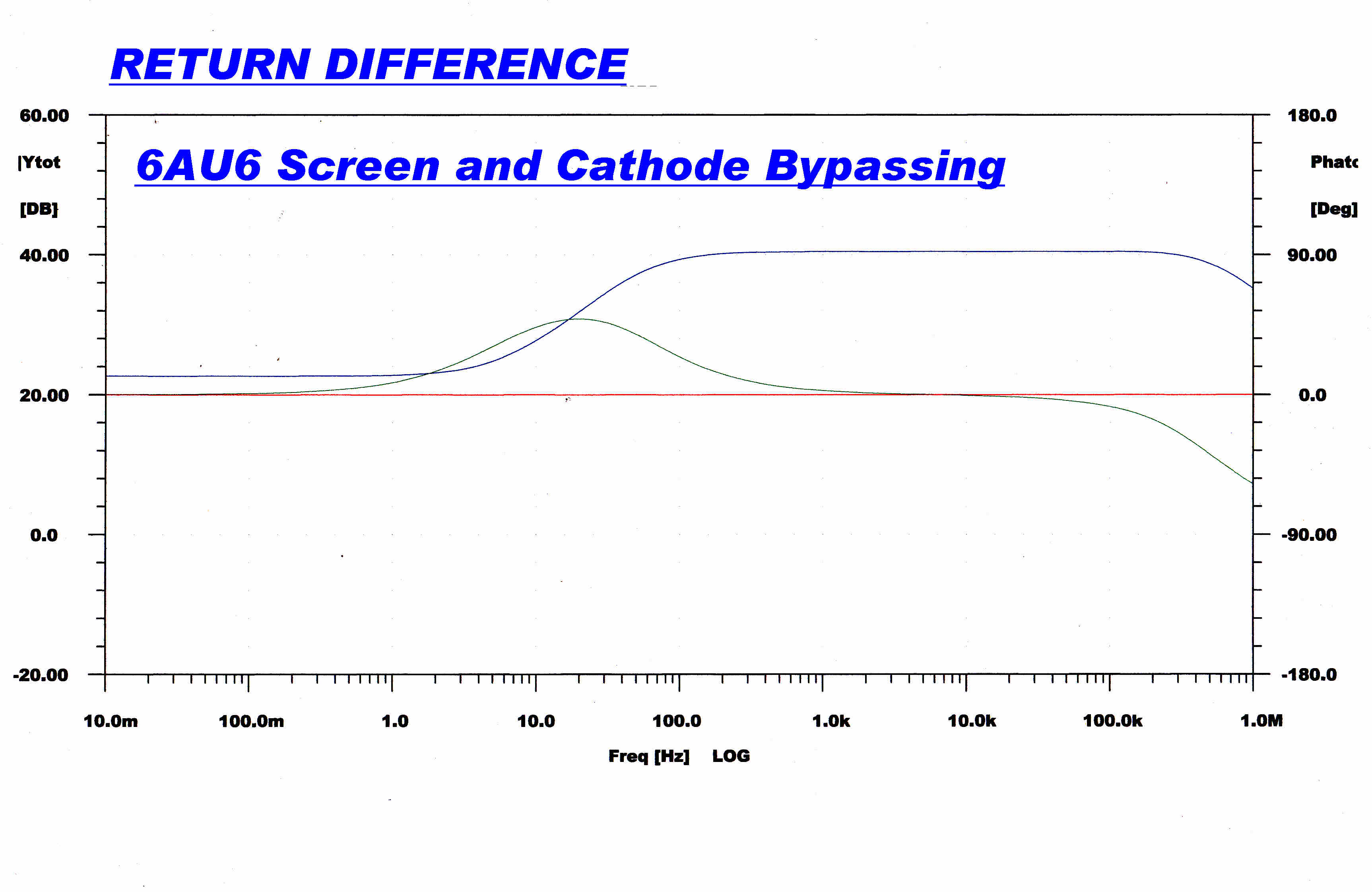
The cathode and screen bypass capacitors C2 and C6 form shelfs.
These can be designed to provide a gentle slope without increasing the
phase margin in the loop. Since the algebra is formidable they are best designed
experimentally.
A computer program to predict the overall closed loop response is set up.
The bypass capacitors are then chosen to eliminate any low frequency peaks
in the response.
The response due to the cathode and screen bypassing alone is shown opposite.
|

|
|
The open loop response is shown above. |
The return difference is shown above. |
|
|
|
The overall steady state response. |
Here the overall steady state response is shown with fine resolution. |
|
|
|
The fast step function response. |
The slow speed transient response.. |
The 6AU6 plate current is related to the grid voltage by a power
law:-
y = ( 1 + x )n .............(1)
If we disturb the plate current with a small sinusoidal input of amplitude a then:
x = a sin(ωt ) ...................(2)
( 1 + x )n = 1 + nx + [ n(n - 1 )/2!]x2 +
[n(n-1)(n-2)/3!]x3 . . . . . . (3)
Substuting (2) in (3)
y = 1 + ansin(ωt) + [n(n -1 )/2]a2sin2(ωt)
But sin2(ωt) = (1/2)( 1 - cos(2ωt )
y = 1 + ansin(ωt) + [n(n -1 )/4]a2( 1 - cos(2ωt ))
y = {1 + [n(n -1 )/4]a2} + ansin(ωt)
- [n(n -1 )/4]a2cos(2ωt)
Since a is very small this equation is a good approximation .
Interpreting each term:
{1 + [n(n -1 )/4]a2} ::: The pentode plate current increases slightly with
signal by k0 where k0 = an(n - 1 )/4.
ansin(ωt) ::: The wanted signal on the output.
[n(n -1 )/4]a2cos(2ωt) ::: The second harmonic distortion.
The fractional second harmonic distortion k2 is given by:
k2 = (amplitude second harmonic/ fundamental)
= na/[n(n -1 )/4]a2
= a( n - 1 )/4
Here the plate current = 2Ma
The peak output voltage is 1 volt aross 100kohms so ΔI for the plate =
1/105
a = 10-5/2x10-3 = 5x10⁻³
For the 6AU6 at Ip = 2 Ma n = 3/2
Substituting we get:
k0 = 4.69x10⁻⁶
k2 = 6.25x10⁻⁴
Conclusion: There is negligible change in plate current with signal
and the distortion before feedback is less than 0.1%.
Since the return difference is over 40db over most of the pass band,
the distortion is further reduced by a factor of 100.
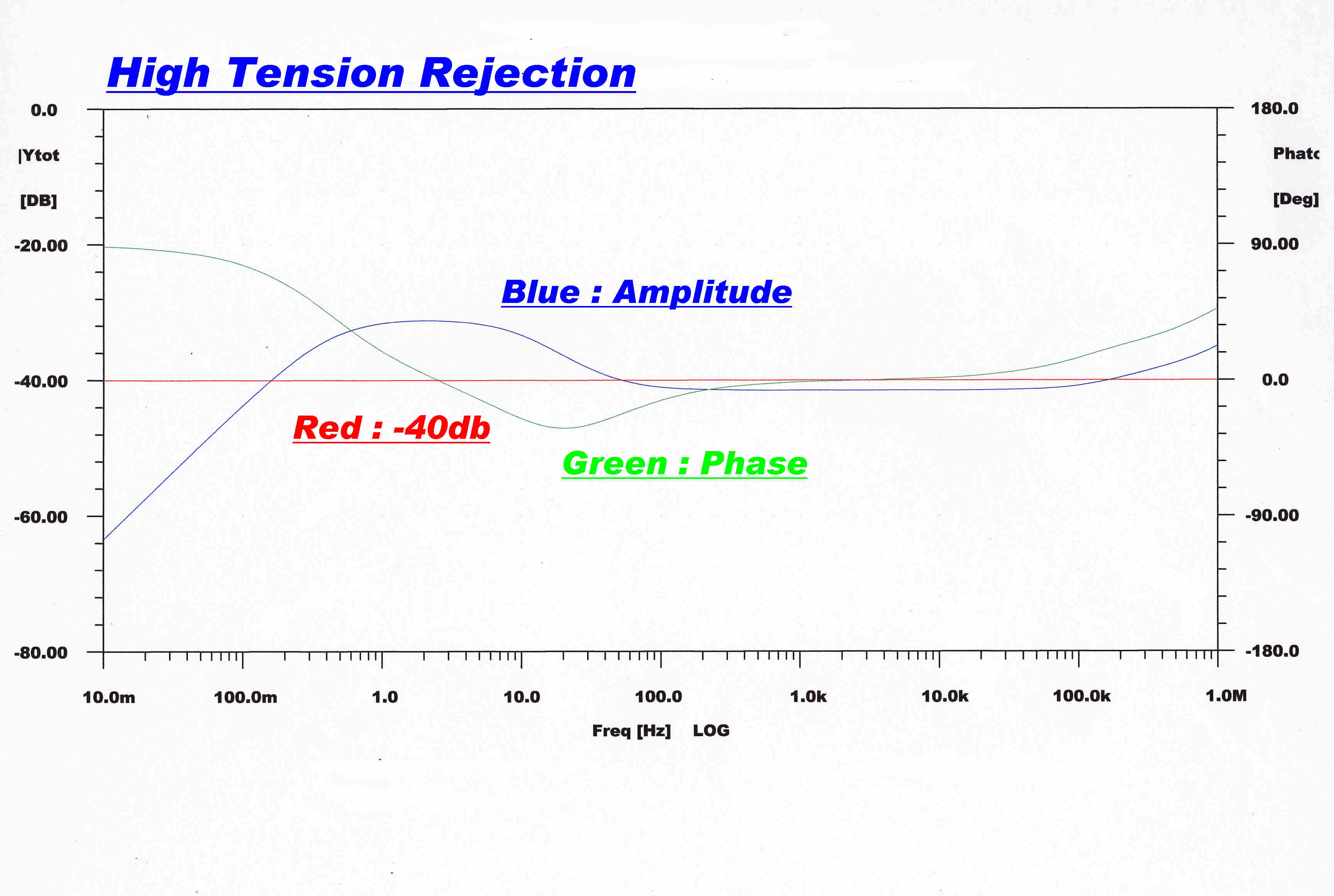 The coupling between the high tension line and the
amplifier output is shown on the right.
The coupling between the high tension line and the
amplifier output is shown on the right.
There is a direct path between the HT line and the output via the pentode
plate resistor, so HT isolation is entirely due to feedback.
The return difference is about 42db above about 50 Hz, and this corresponds with a
HT signal rejection of 42db.
This attenuation, coupled with the performance of the HT regulator, ensures low
hum level and stage interaction.
A calculation of the gains around the low frequency disc equalisation
system gives a better understanding of the action.
The frequency chosen for the calculation is 250Hz, the bass turnover frequency.
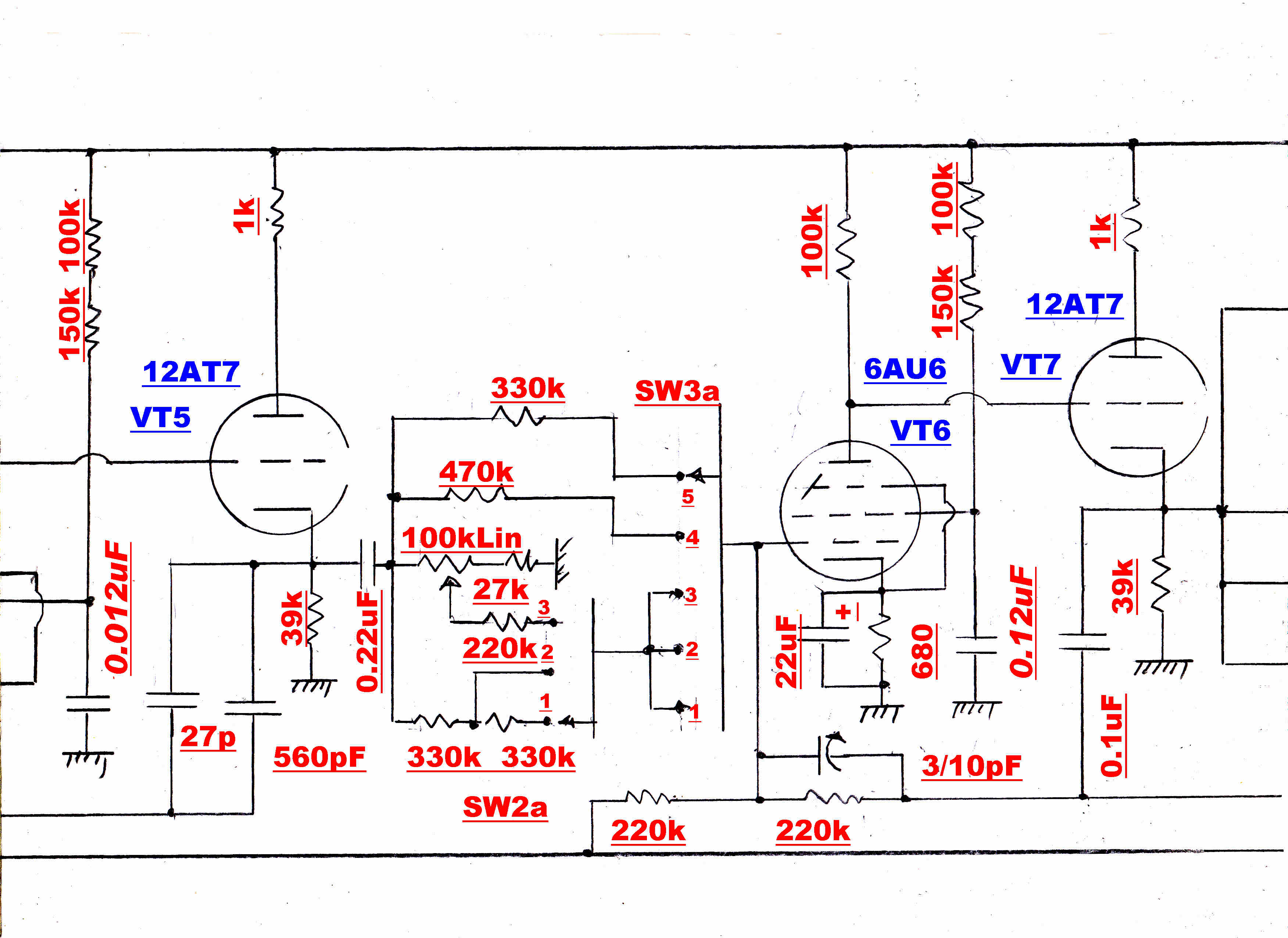
For ease of reference the full circuit diagram is repeated.
|
|
|
|
The constant velocity signal is sign reversed in VT3,
integrated in VT4 VT5 and summed in VT6 VT7.
Analysis shows that the sign inverter VT3 acts as a voltage
generator -μeg with an output resistance of
Rout = [ Rp + ( μ + 1 )Rk ]
Because of the high gain around VT4 VT5, the grid of VT4 is a
virtual earth. The load on VT3 is then 100k||220k||820k = 63.43k
For VT3: Vp = 200V: Ip = 1Ma: μ = 42 ;
Rp = 18.26k
The gain of the sign inverter is therefore 0.6080
The integrator VT4 VT5 gain approximates the ratio of the reactance of the
587pF feedback capacitor to the 220k front resistor at 250Hz: 4.9296
The gain in the summer = 220k/660k = 1/3
The overall gain for the integrator at 250Hz is then:
A250 = 0.6080 x 4.9296 /3 = 1.
Below 250Hz the signal through the integrator will prevail and give a
response rising at 6db/octave.
Above 250Hz the response will be flat.
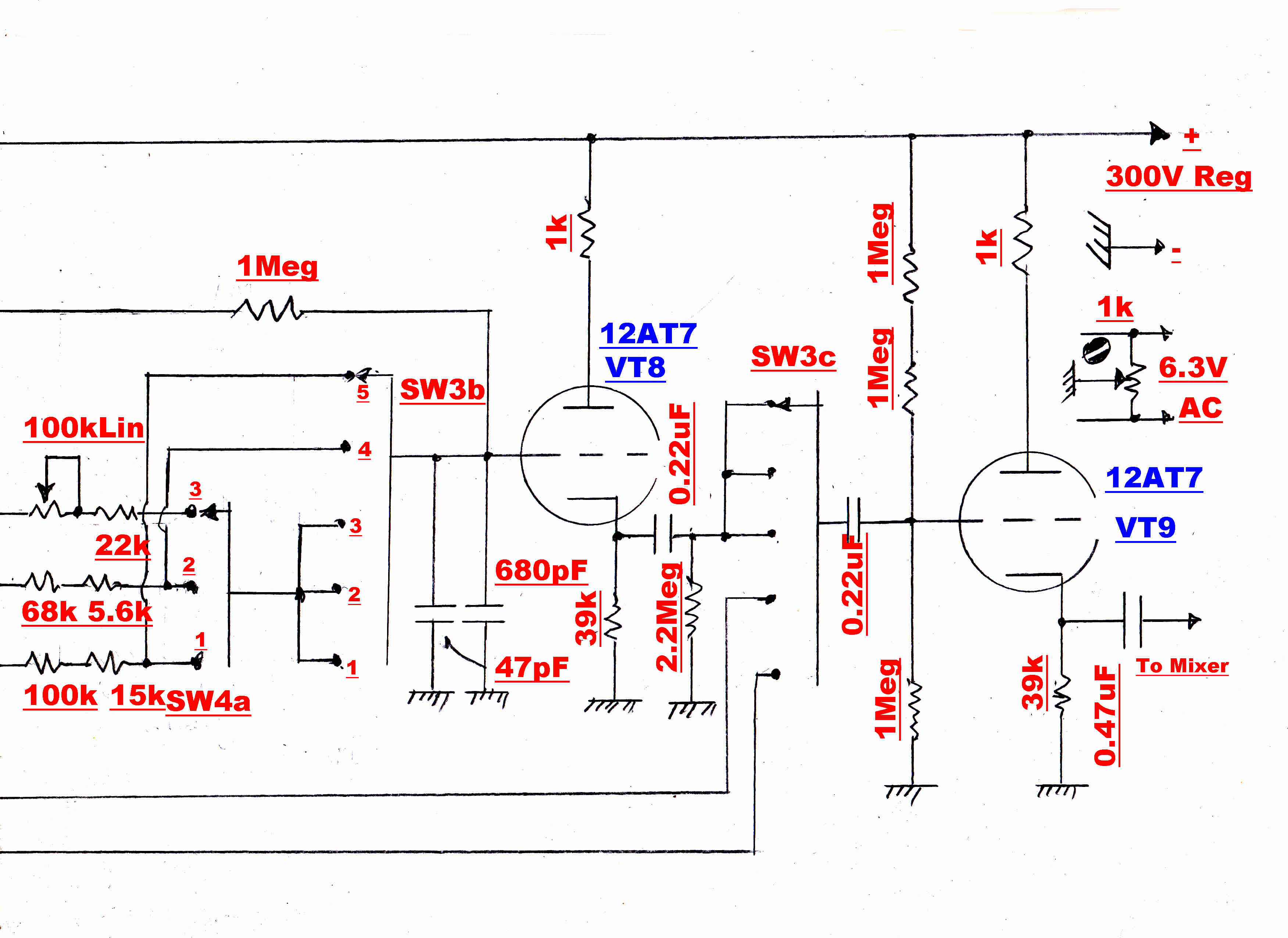
A single order R-C filter between the cathode of VT7 and the
grid of VT8 provides a 6db/octave top cut filter to equalise preemphasis.
A 1Meg resistor is left permanently bridged across the switch to remove
transients on switching.
The total capacity is 727pF.
fc = 1/(2 π R|| C )
For SW4a:-
(1) Position 1 RIAA Microgroove
R|| = 115k||1Meg = 103.14K : fc = 2122HZ
(2) Position 2 RIAA 78
R|| = 73.6K||1Meg = 68.55K : fc = 3193HZ
(3) Position 3 Adjustable
For fmin
R|| = 122K||1Meg = 108.73K : fc = 2.01KHz
For fmax
R|| = 22k||!Meg = 21.526K : fc = 10.17KHz.
In the following tracks the channel balance is slowly
altered from one extreme position to the other.
With the lateral disc, the fundamental signal reaches a minimum as the pinch effect
distortion reaches a maximum. This is the correct setting for playing mono lateral discs.
The process is repeated a number of times from the start of the disc to the finish.
With the lateral disc the pinch effect distortion increases towards the centre
as expected.
The vertical cut disc, with no pinch effect, is much better behaved and remains
the same throughout.
Test Conditions:-
Stylus: 2.5thou spherical
Cartridge: Stanton 500 MkII
Playing Weight: 4gms
Equalisation:
Lateral : RIAA
Vertical : Constant Velocity
Disc Details:
Cry of The Wild Goose
Frankie Lane
Mercury
Matrix ESQ16A
Play Lateral Track
Disc Details
Little Peach
Edison Acoustic Diamond Disc
Matrix : 10290
Play Vertical cut Track