UNIVERSAL TONE CONTROL
CONTACT : COMMENTS AND QUESTIONS
back/home
This section describes the design and performance of a universal tone control.
Often it is desirable to modify the response to program material, especially material
from old sources.
The tone control can provide either a boost or cut independently at high and low frequencies.
The onset frequency of the bass or treble boost or cut can also be independently controlled.
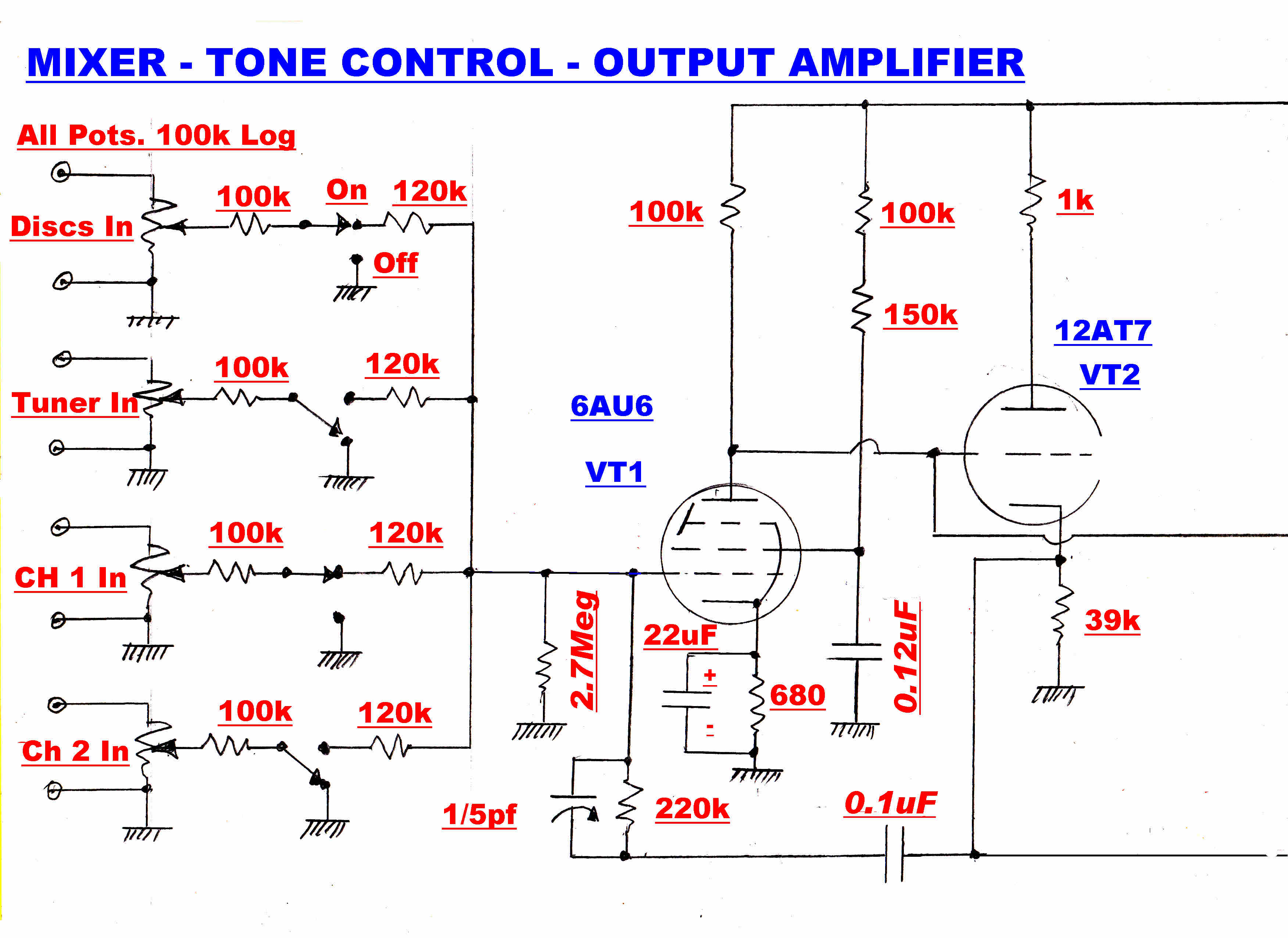
(1) Four Channel Mixer
The input stage is designed as a four channel mixer.
(2)
The Tone Control has four controls:-
(a) Bass Cut or Boost.
On center this control provides a flat response.
Clockwise it provides a maximum boost of 16db.
Counter clockwise it provides a maximum cut of 10db.
(b) Bass Frequency
This controls the turnover frequency of control (a) over a range of 20:1.
The interaction between controls (a) and (b) is analysed below.
(C) Treble Cut or Boost.
On center this control provides a flat response.
Clockwise it provides a maximum boost of 16db.
Counter clockwise it provides a maximum cut of 10db.
(d) Treble Frequency
This controls the turnover frequency of control (c) over a range of 100:1.
The interaction between controls (c) and (d) is analysed below.
(3) Output Amplifier
It is frequently desirable to have the preamp - disc eqialiser and tone control
separate from the power amplifier and speakers.
The output amplifier has been designed to drive 10 metres of unterminated cable.
Most power amplifiers have an input resistance above 100k and satisfy
this condition.
The complete circuit of the disc tone control is shown below:
|
|
|
|
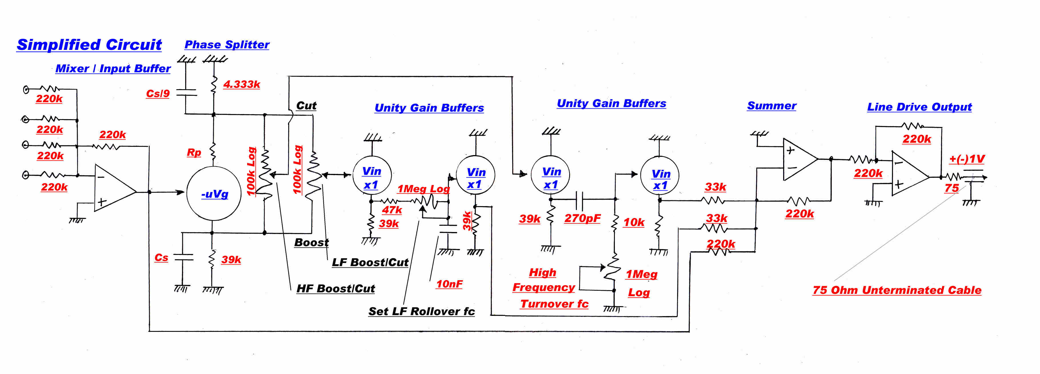
The input amplifier consists of VT1 and VT2 and is represented in the simplified
circuit as an operational amplifier.
The high degree of feedback forms a virtual earth on the grid of VT1.
This prevents interaction and coupling between the four inputs.
The overall gain is very nearly unity and the low output impedance
provides a convenient drive to the tone control.
The 6AU6 - 12AT7 amplifier configuration is used throughout the tone control.
It has an overall gain of 218.
Its design and details are given in the preamplifier- equaliser section.
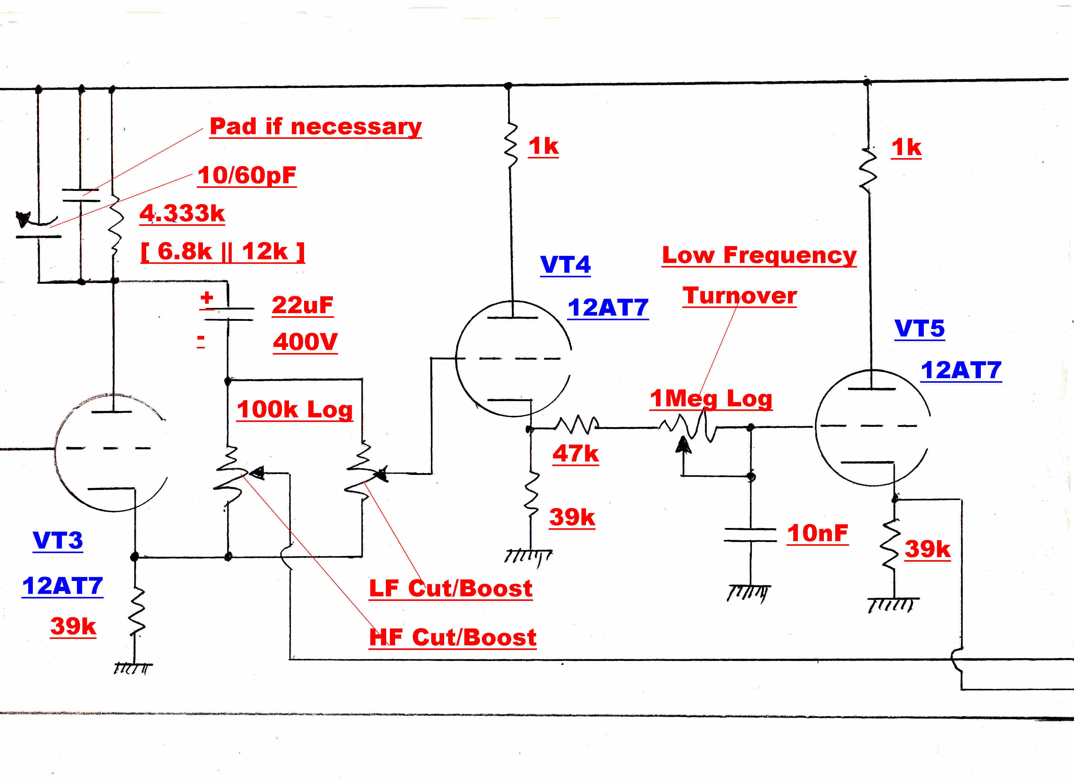
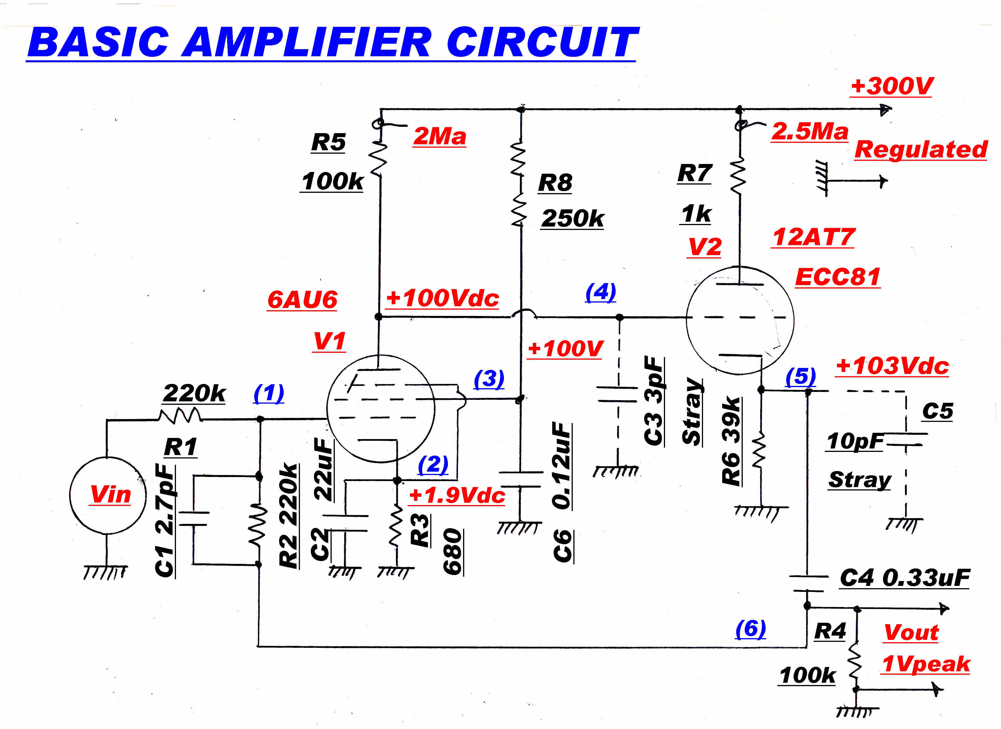 The amplifier shown on the right is the basic building block of the tone control.
It consists of a pentode voltage amplifier - 6AU6 - followed by a triode
cathode follower - 12AT7.
The amplifier is used as a summing amplifier with a large degree of feedback.
The cathode follower and high voltage feedback produce a low output impedance.
The feedback also makes the amplifier immune from transients on the
high tension line which is supplied from the high performance regulator.
The output from the 100k (log) boost- cut potentiometers is (+1) x the input
when set to the boost end.
Zero when centered.
And ( -1/9 ) x the input when at the cut end.
The low frequency channel is filtered by a single order lowpass filter and
added to the original signal. The roll over frequency is set by a 1Meg ohm pot.
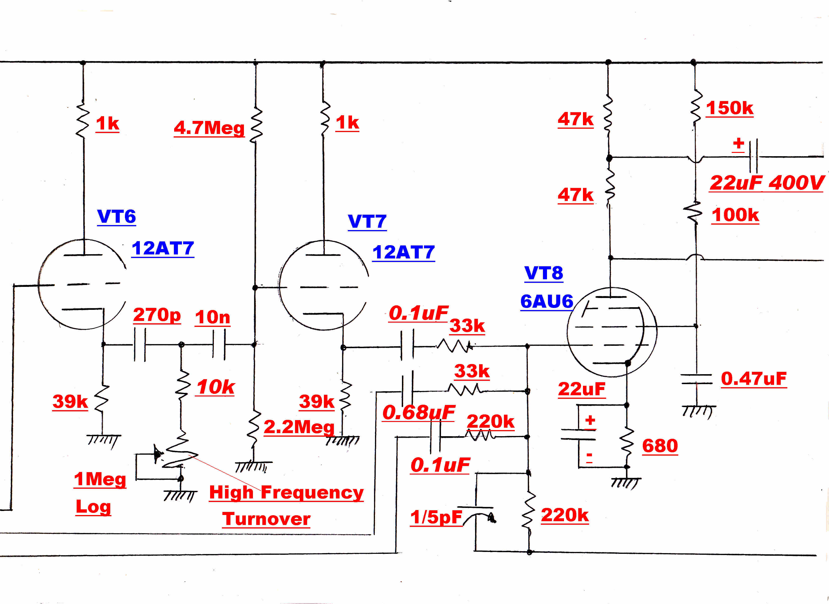
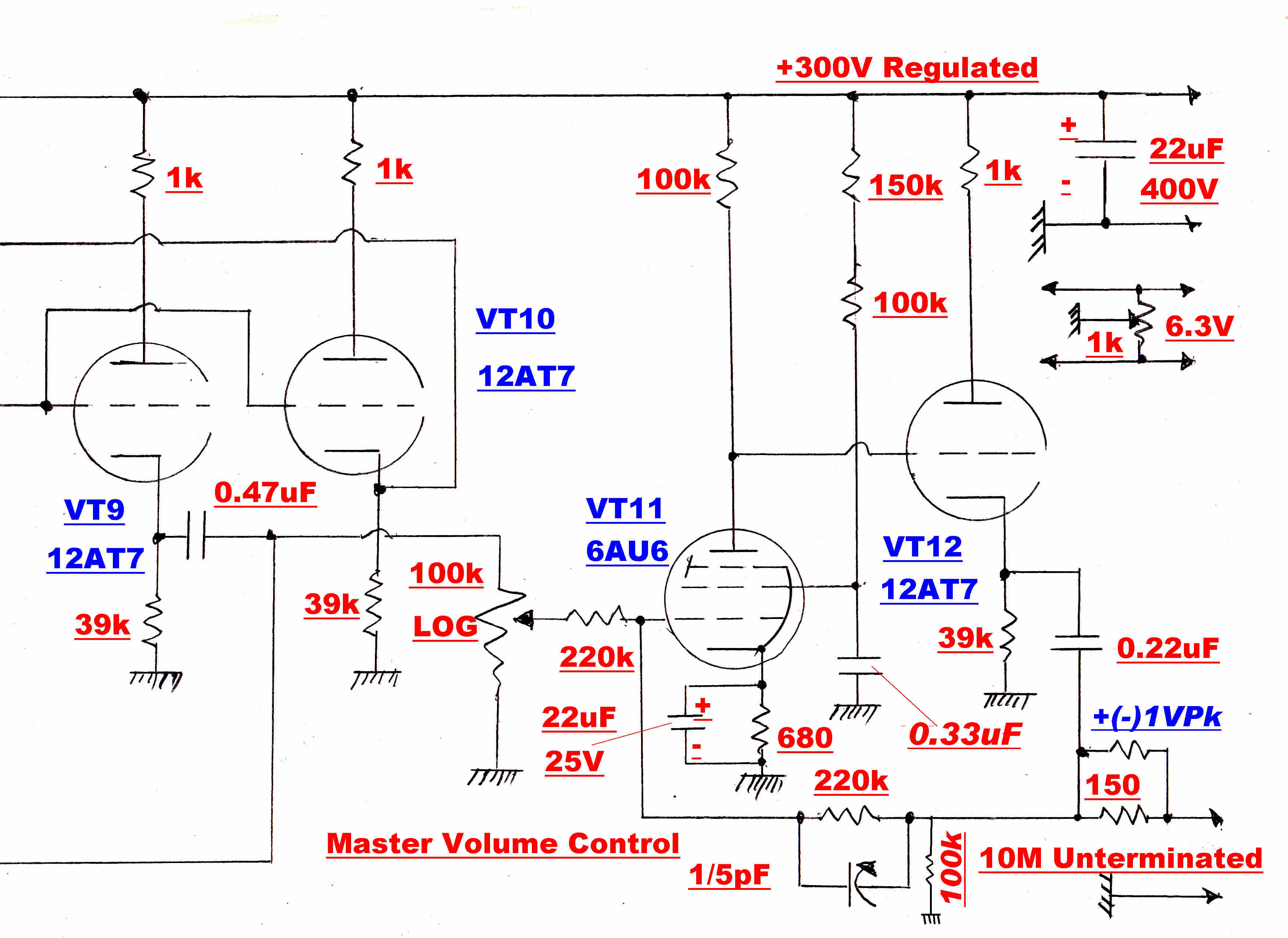
The two signals from the potentiometers and the input signal are then added
algebraically in the summing amplifier VT8, VT9, VT10.
When the signals add, boost occurs - when the signals subtract cut occurs.
The high frequency channel is filtered by a single order highpass filter and
added to the original signal. The roll over frequency is set by a 1Meg ohm pot.
When the signals add, boost occurs - when the signals subtract cut occurs.
The high and low frequency responses are completely independent.
VT3, the 39k cathode load, the 4.333k plate load and the two 100k potentiometers
form a bridge which is balanced when the potentiometers are centered.
Note: When 100k Log potentiometers are centered, the resistance of
the two sections is 10K and 90k.
This means that there will be no output from a centered potentiometer
if the ratio of cathode to plate voltage is 9:1.
At audio frequencies the same current flows in the cathode and plate circuit,
so the total resistance in these circuits must have a ratio of 9:1.
Imagine the potentiometers centered with no voltage appearing on their outputs.
The potentiometers present a load of 90k/2 = 45k to the cathode.
The total cathode resistance is 39K//45K = 20.893k
The total plate load must be 20.893k/9 = 2.321k
The load presented to the plate by the potentiometers is 10k/2 = 5k
The plate load must now be 4.333k since 4.333k//5k = 2.321k.
The 4.333k load is best made up of a 3.9k resistor in series with a 1k
linear trim pot.
High Frequency Balance
It is important that the bridge remain balanced well above 20kHz.
The leads from the cathode of VT3 to the potentiometers mounted on
the front panel will have considerable capacity to earth. This is
shown on the simplified circuit as Cs.
A capacity Cs/9 must be added to the plate circuit to restore balance.
The single order R-C low pass network between VT4 and VT5 has a variable
turnover frequency from 15.2Hz to 339Hz.
The single order R-C high pass network between VT6 and VT7 has a variable
turnover frequency from 977Hz to 59.3KHz.
The two 33k resistors added to the front of the mixing amplifier reduce
the gain around the feedback loop.
The open loop amplifier gain must be increased to compensate for this.
The gain is increased by bootstrapping the load on VT8 through the
cathode follower VT10.
This increases the load resistor, and hence the gain of VT8, by a factor
greater than 20.
|
|
|
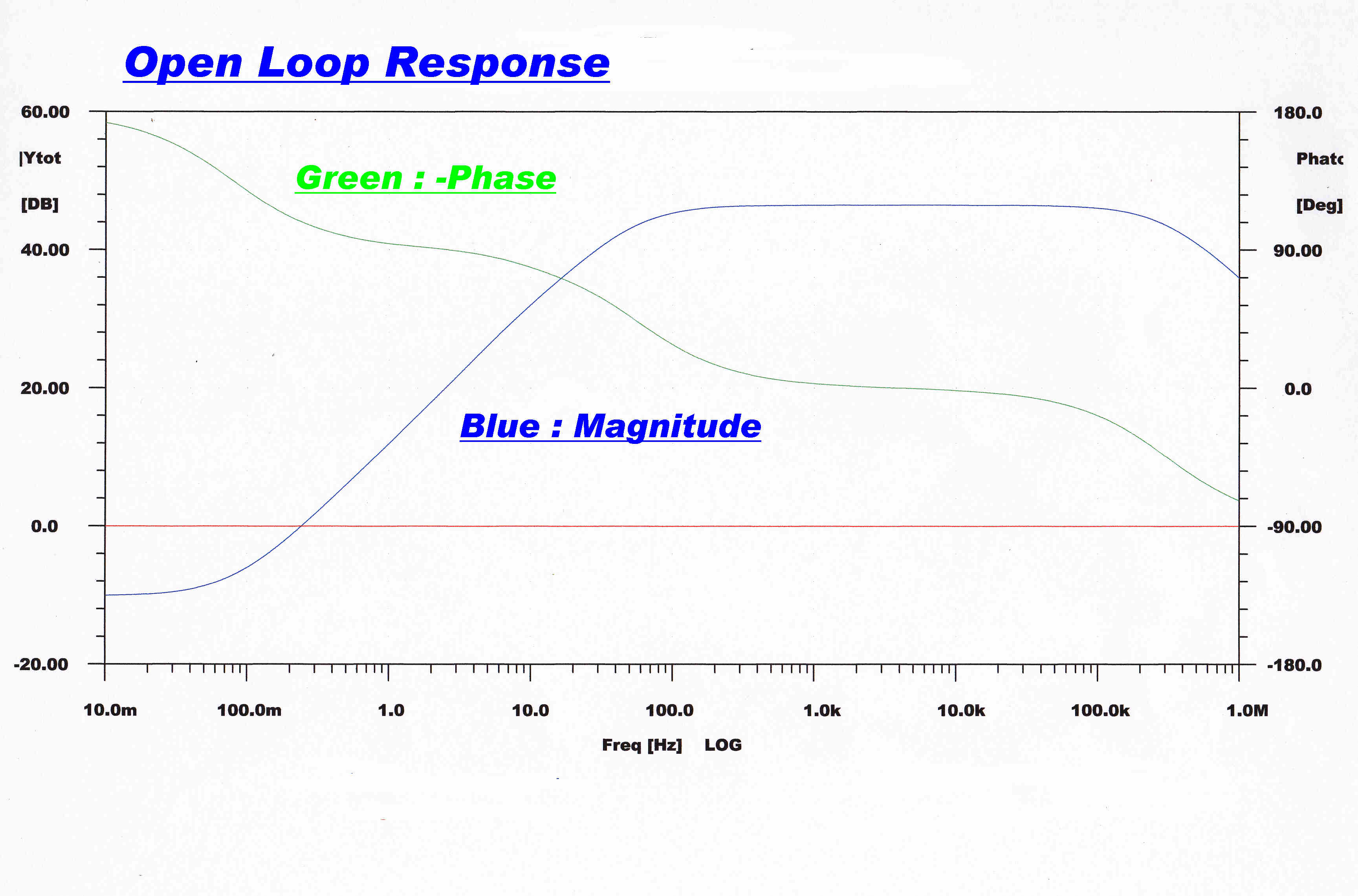
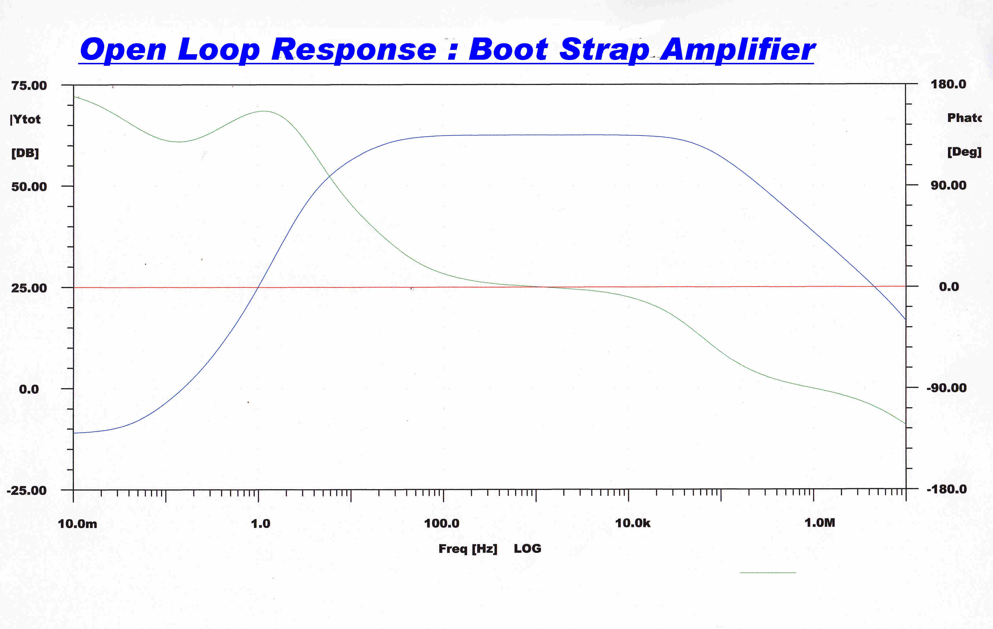
This is the open loop response of the basic amplifier without bootstrapping. |
The amplifier response with bootstrapping showing the increase in gain. |
The line drive amplifier is designed to drive 10 metres
of unterminated 75 ohm coax cable.
The capacity of the cable is about 616pF and its reactance at 20KHz
is 12.92k.
With a peak output of 1 volt the current drive required is 77.4uA
This is easily provided by the cathode follower VT12, which has a
standing current of 2.5Ma.
Because of the heavy feedback, the output impedance looking back into
the cathode follower is close to zero. The output impedance seen by the cable is
therefore 75 ohms resistive.
This terminates any reflected signal.
The transfer function of the tone control consists of a pole and zero on the
negative real axis for low frequencies and another set for high frequencies.
The cutoff frequency control determines the position of the pole, and the
boost - cut control determines the relative position of the zero.
TRANSFER FUNCTION
If the overall gain is unity, the transfer function for either low or high frequencies
can be written:-
Y(p) = 1 + AYc(p)
where Y(p) is the overall transfer function
A is the gain set by the boost- cut control. Positive for boost : negative for cut.
Yc(p) is the single order transfer function set by the frequency control.
Yc(p) = N(p)/D(p)
Y(p) = 1 + A N(p)/D(p)
Y(p) = [D(p) + A N(p)] / D(p)
LOW FREQUENCIES
 For the low frequency channel:-
Yc(p) = 1/( 1 + τp )
N(p) = 1 :: D(p) = 1 + τp
Y(p) = [ ( 1 + A ) + τp ] / [ 1 + τp ]
Y(p) = [ 1 + A ][ 1 + τ/( 1 + A ) p ] / [ 1 + τp ]
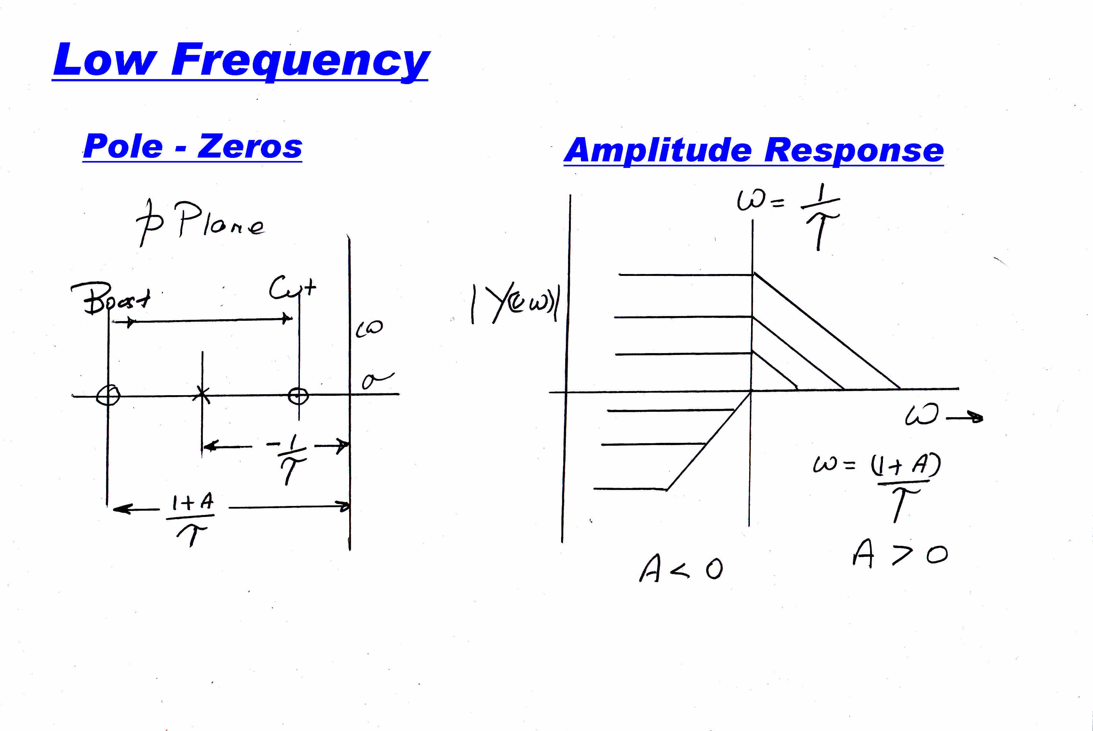
This gives a zero at : -( 1 + A )/ τ :: a pole at -1/τ
Note : A is the relative gain between the direct path to the mixer and the
the path through the R-C network.
BOOST
If A is positve the zero will lie left of the pole and there is a boost
of ( 1 + A ) at DC .
There is a knee at ω = 1/τ
Then there is a 6db/octave slope down to unity gain ending at ω = ( 1 + A )/τ
After this the gain is unity.
CUT
Here the gain A is negative.
If |A| > 1 the zero lies in the right half of the p plane and produces an
unwanted non-minimum phase function.
We then have the condition: -1 < A < 0
The DC gain is ( 1 - |A| )
There is a knee at ω = (1 - |A| )/τ
Then a 6db/octave rise to unity gain at ω = τ
NOTE: The onset frequency of the cut or boost varies with the setting
of the cut/boost potentiometer.
The pole - zero distribution and the steady state frequency response are
shown above.
HIGH FREQUENCIES
 For the high frequency channel:-
The transfer function of the single order high-pass filter is given by:
Yc(p) = τp/( 1 + τp )
N(p) = τp :: D(p) = 1 + τp
Since from above: Y(p) = [D(p) + A N(p)] / D(p)
Y(p) = [ 1 + τp + A τp ]/[ 1 + τp ]
Y(p) = [ 1/(τp) + ( 1 + A ) ]/[ 1/(τp) + 1 ]
For low frequencies the 1/(τp) terms are very large and the transfer function
equals 1 . The tone control is flat with a gain of unity.
The ultimate gain at high frequencies is ( 1 + A )
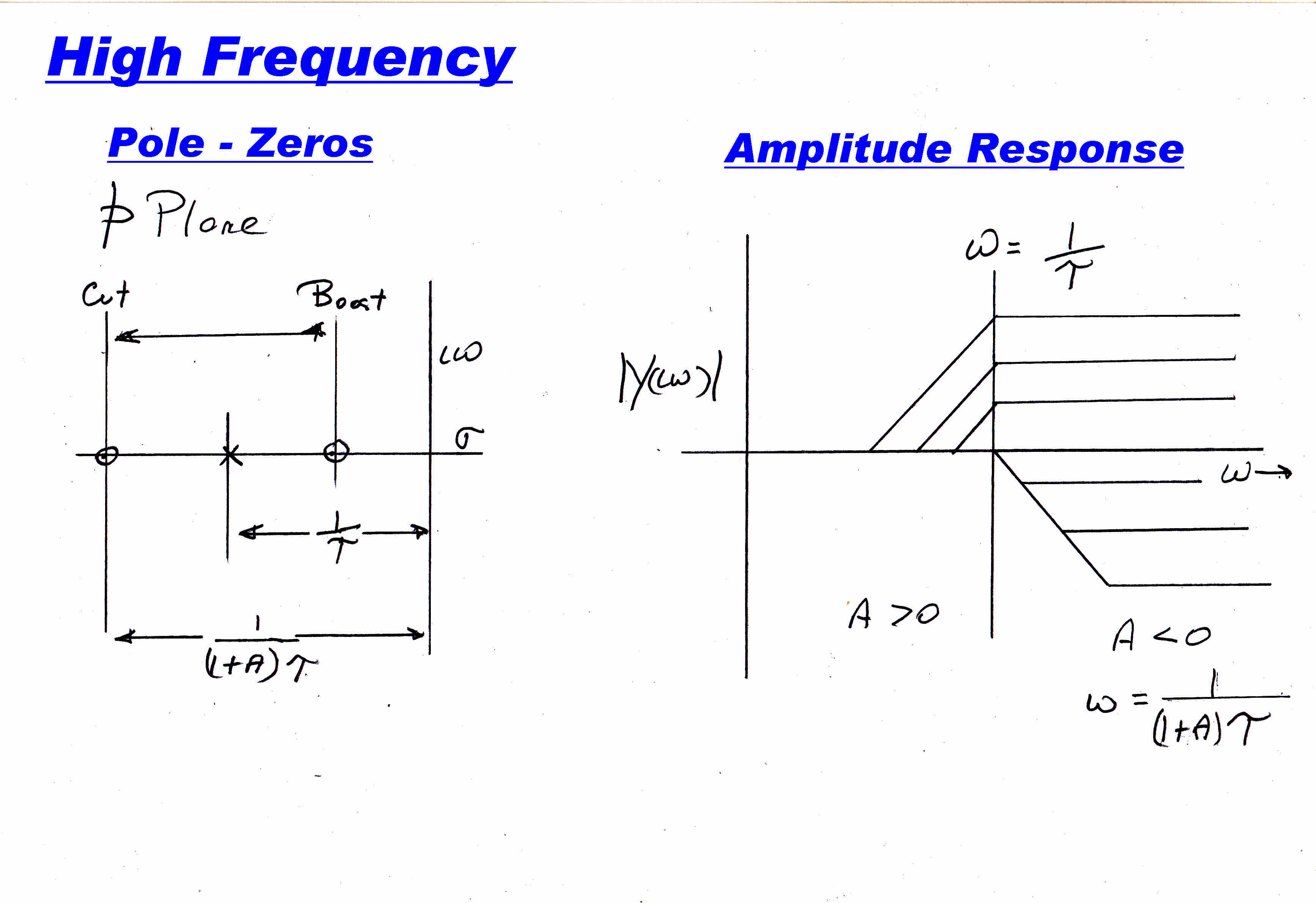
The frequencies of the zero ωz and of the pole ωp are given by:
ωz = 1/[ ( 1 + A )τ]
ωp = 1/τ
BOOST
For boost A is positive. The zero lies between the pole on the negative
real axis and the origin.
Boost begins at ω = 1/[ ( 1 + A )τ] and ends at ω = 1/τ
The ultimate high frequency gain is ( 1 + A )
CUT
Here the gain A is negative.
If |A| > 1 the zero lies in the right half of the p plane and produces an
unwanted non-minimum phase function.
We then have the condition: -1 < A < 0
Treble cut starts at a frequency ω = 1/τ and ends at a frequency
ω = 1/[ ( 1 - |A| )τ ]
The ultimate high frequency gain is ( 1 - |A| )
|
|
|
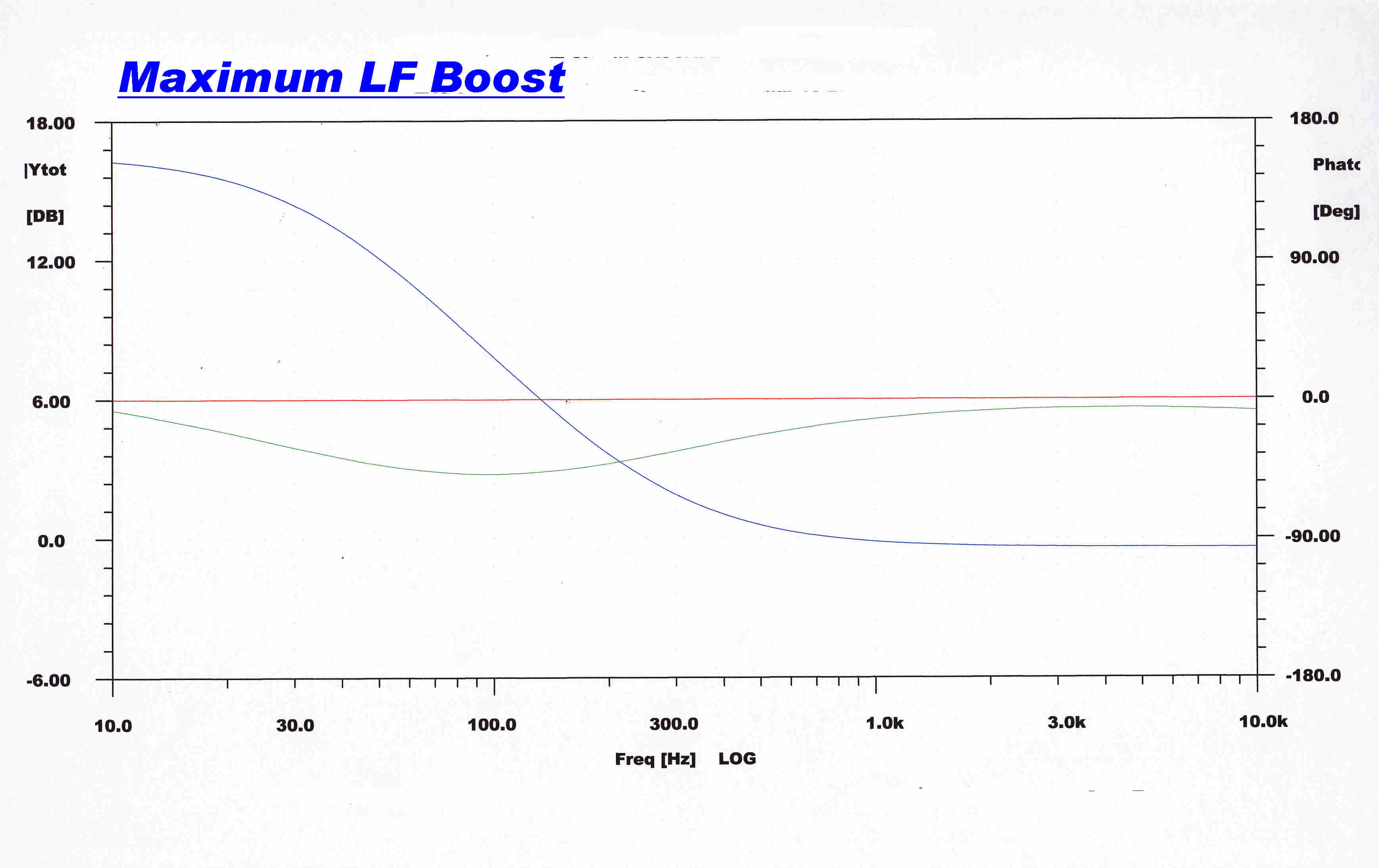
The typical response of the tone control on full low frequency
boost is shown above. |
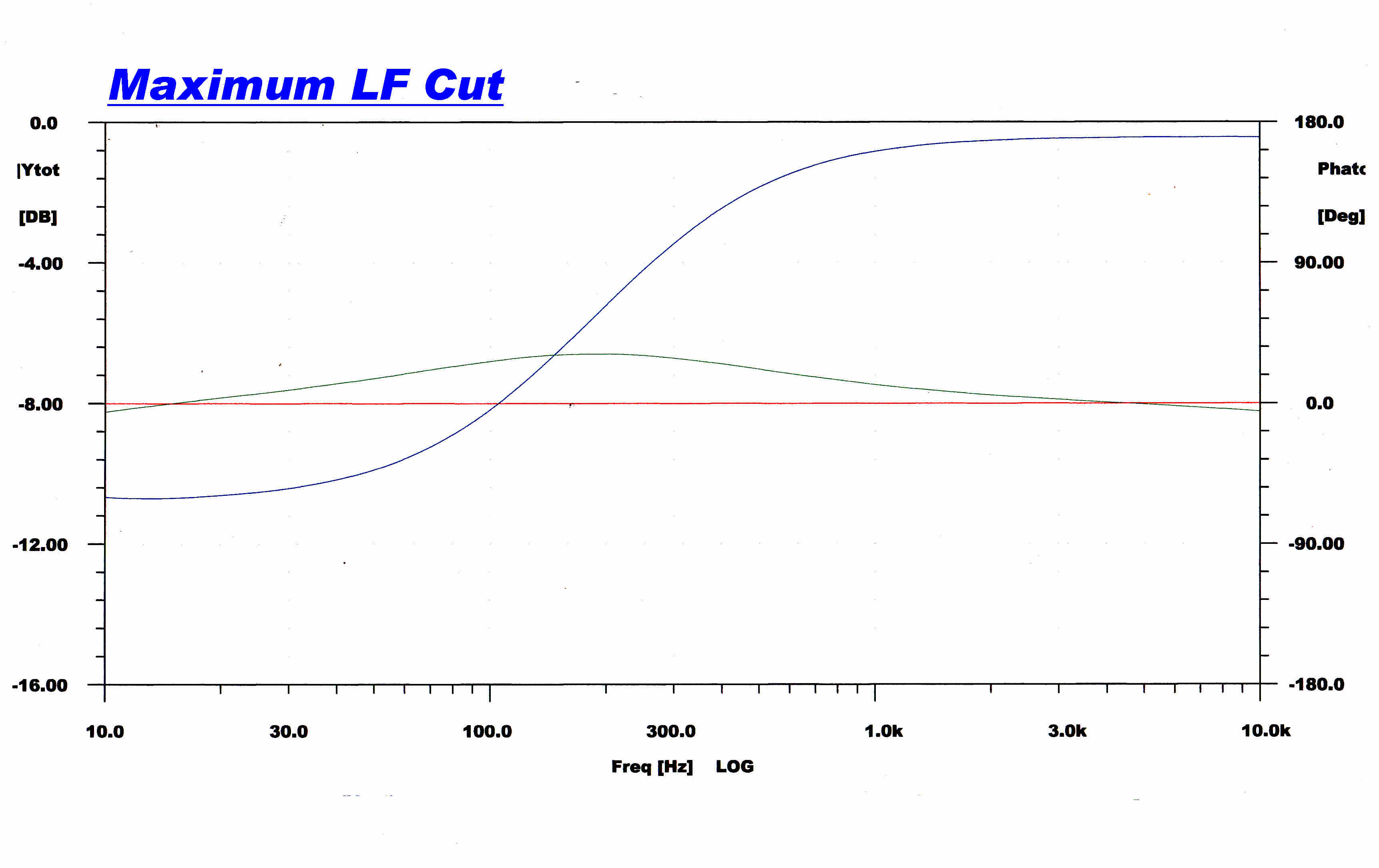
The typical response of the tone control on full low frequency
cut is shown above. |
|
|
|
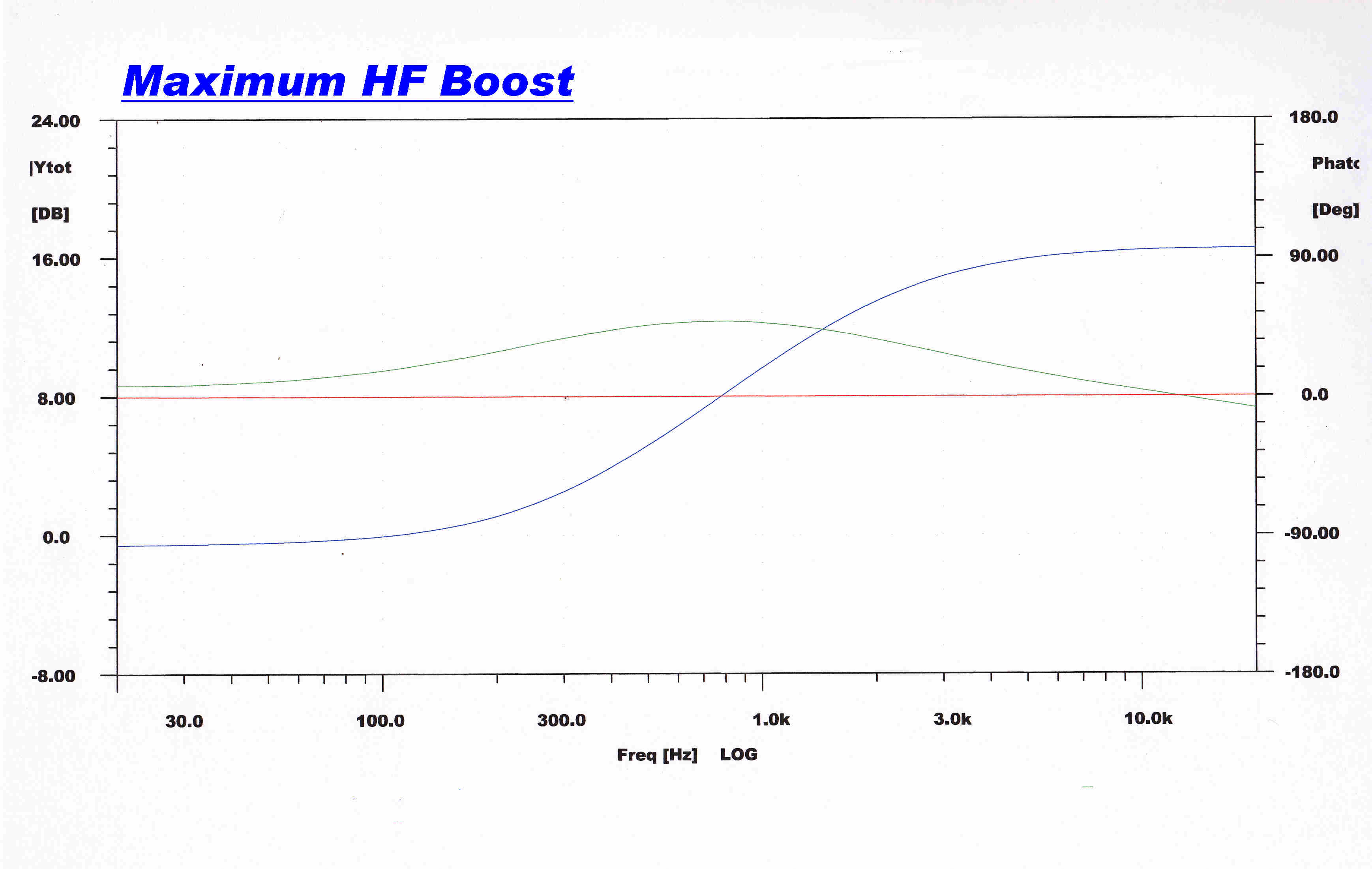
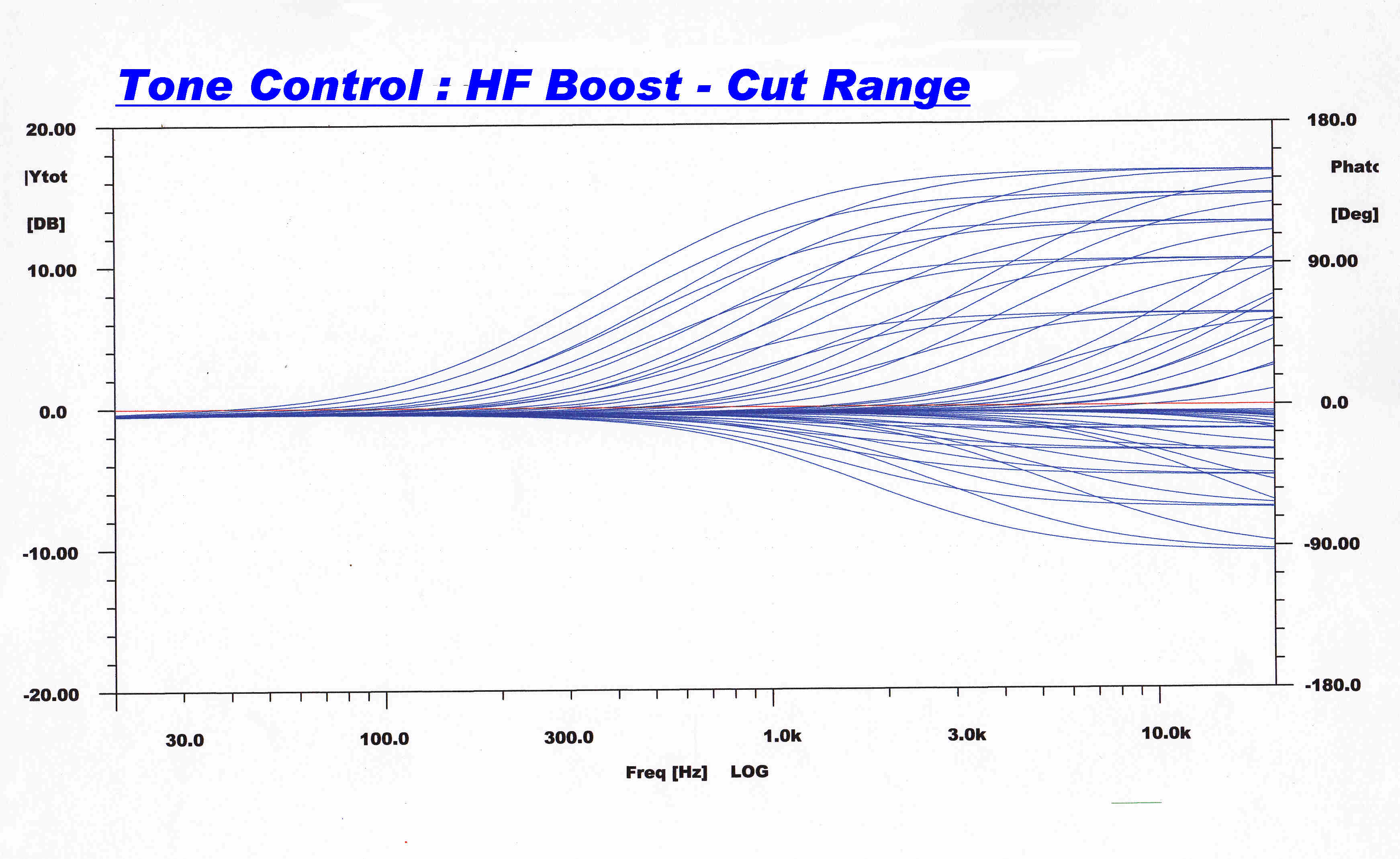
The typical response of the tone control on full high frequency
boost is shown above. |
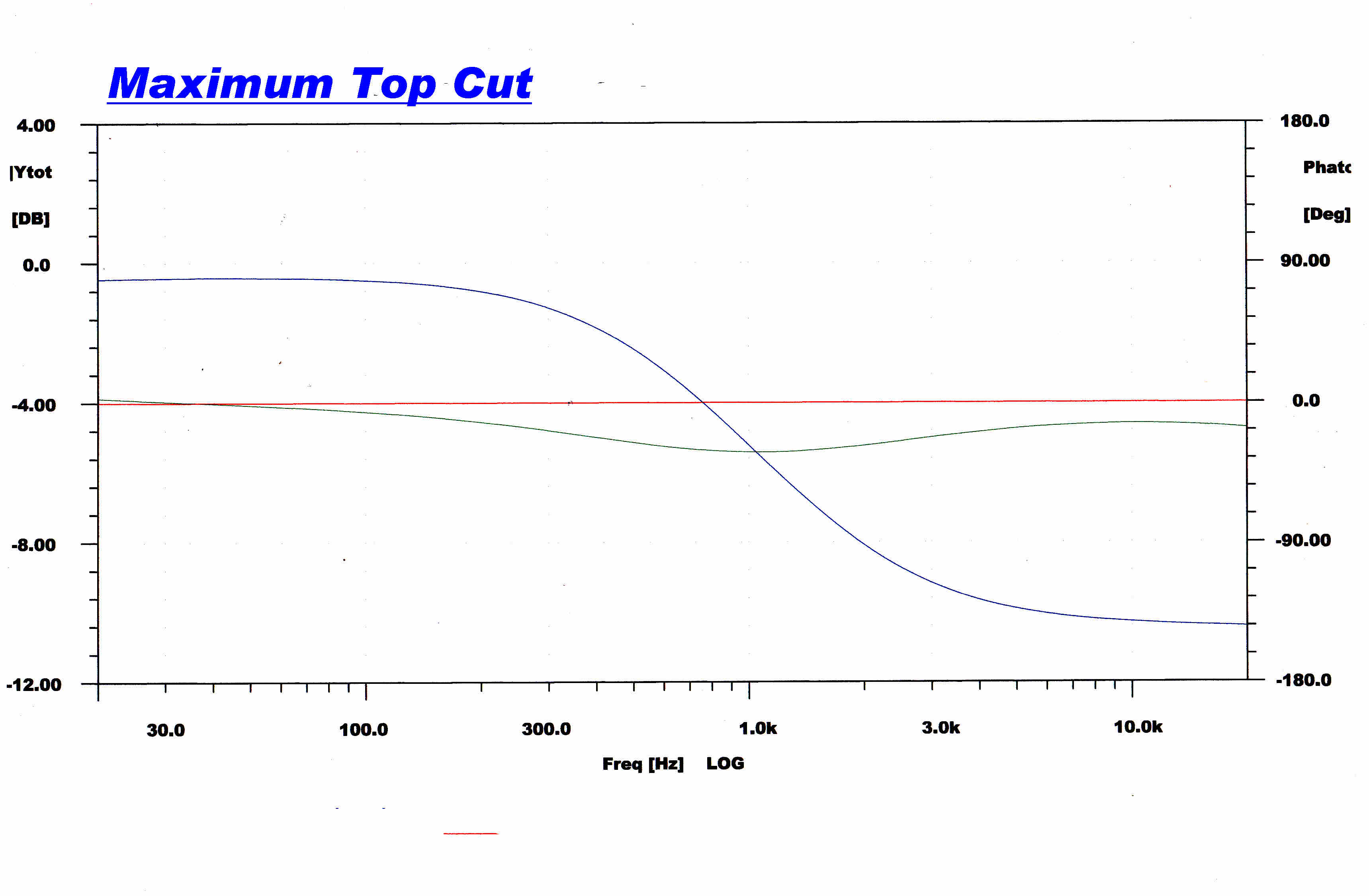
The typical response of the tone control on full high frequency
cut is shown above. |
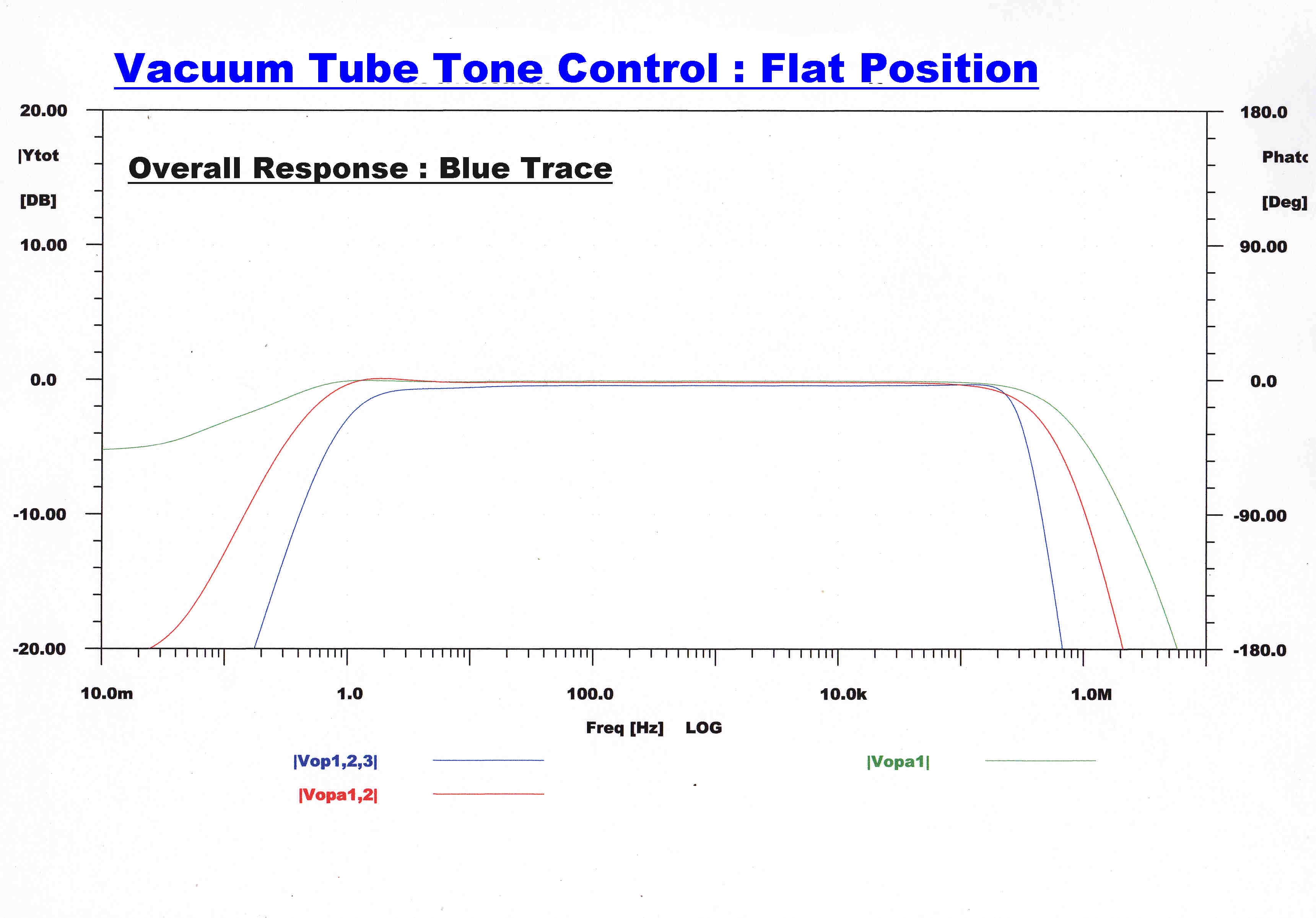
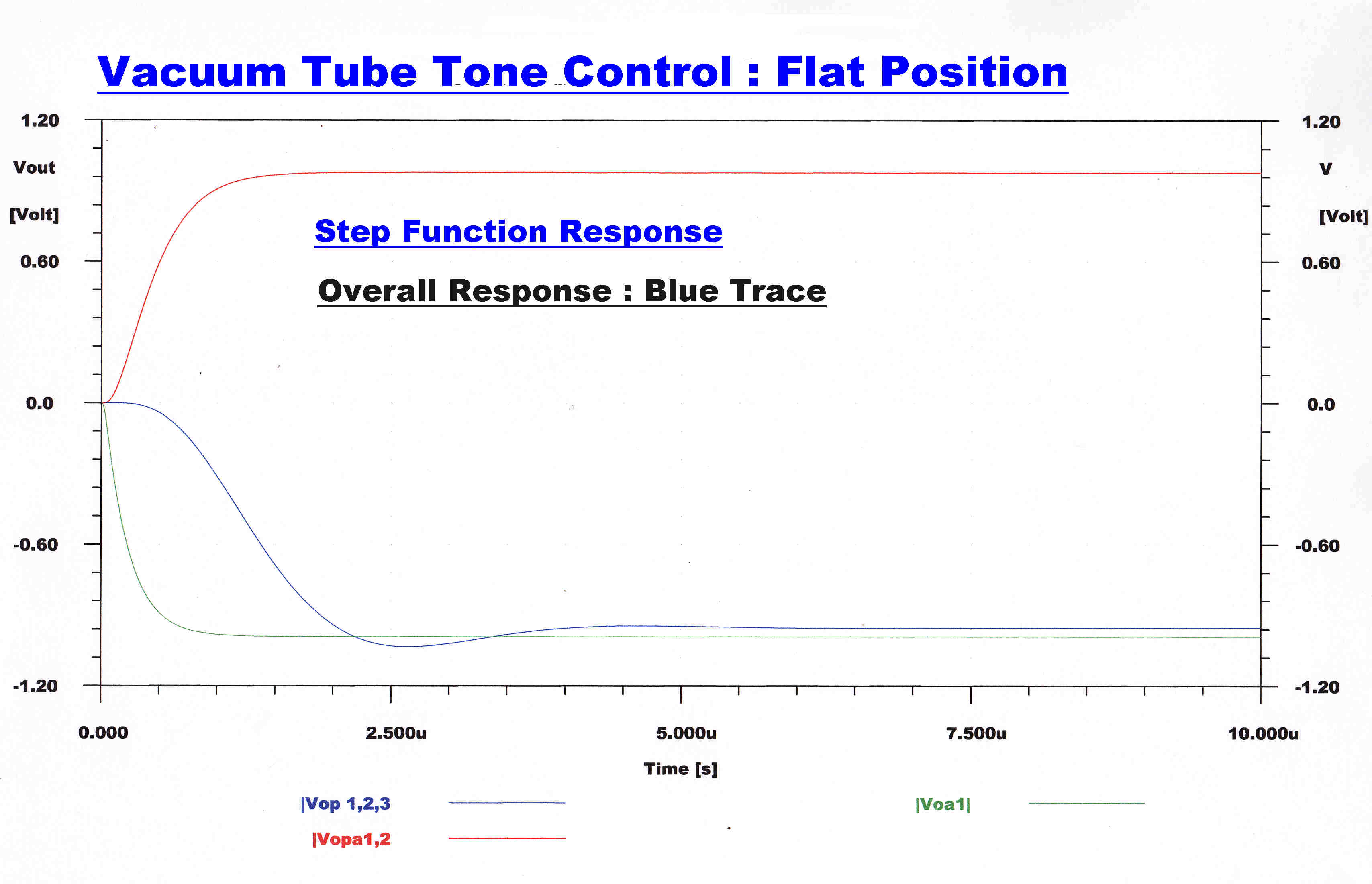
The response to the signal as it passes through the three stages of the
tone control ( in the "flat" position ) is shown below.
|
|
|
Overall Steady State Response |
Fast Step Response |
|
|
|
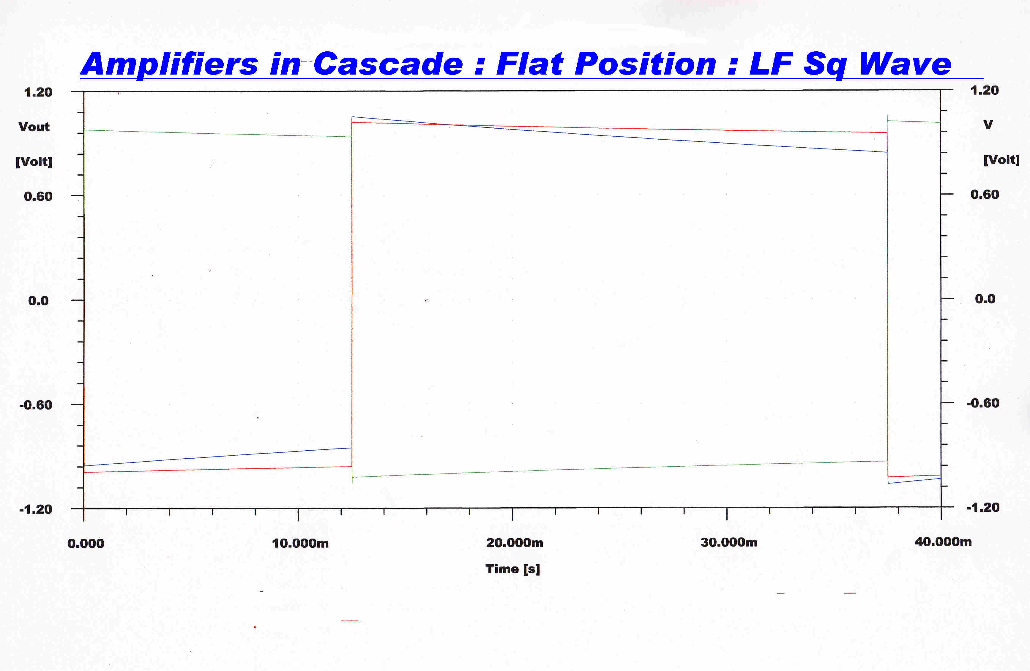
Overall Response to 20 Hz Square Wave |
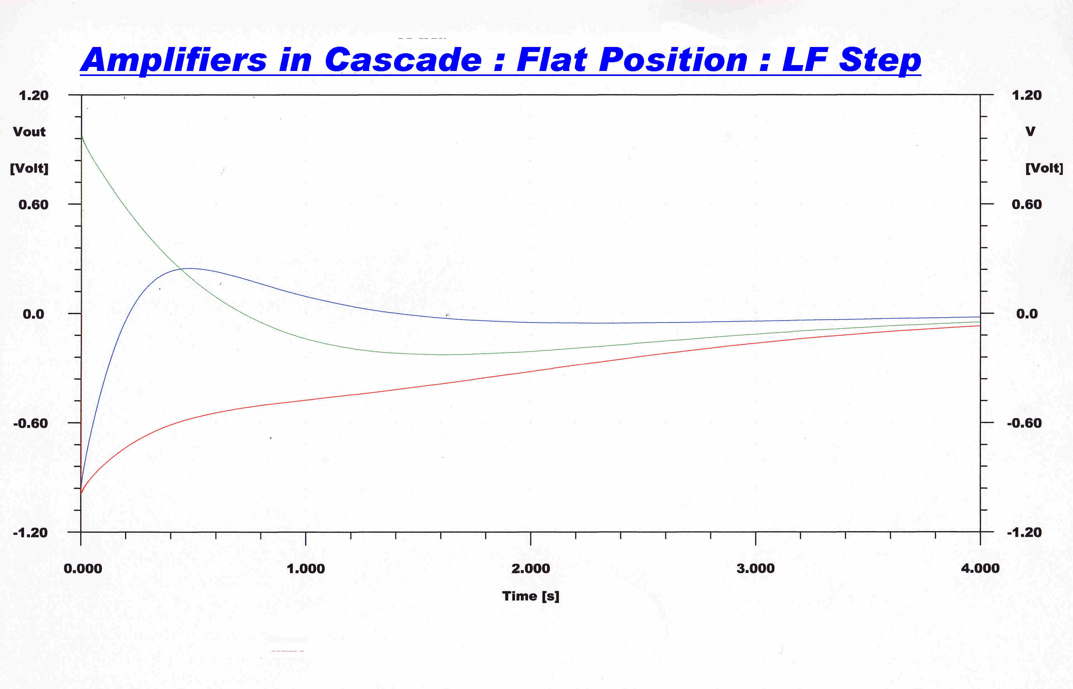
Overall Long Term Step Response |
The responses are plotted in the following manner:
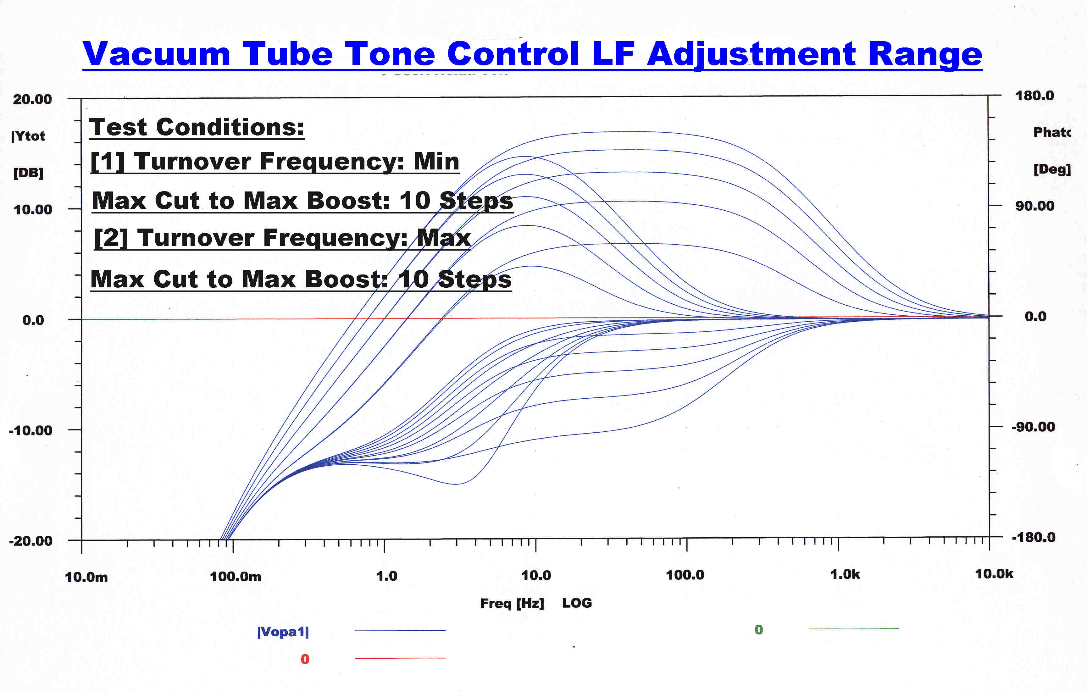
The full range of low frequency responses possible with the tone control.
The initial step is unity since the high frequency response is unity.
The full range of high frequency responses possible with the tone control.
Since the low frequency response is unity, all responses approach 1.
(1) The tone control is placed on maximum boost and the frequency
control is moved through its full range.
(2) The tone control is placed on maximum cut and the frequency
control is moved through its full range.
All possible responses fall within this envelope.
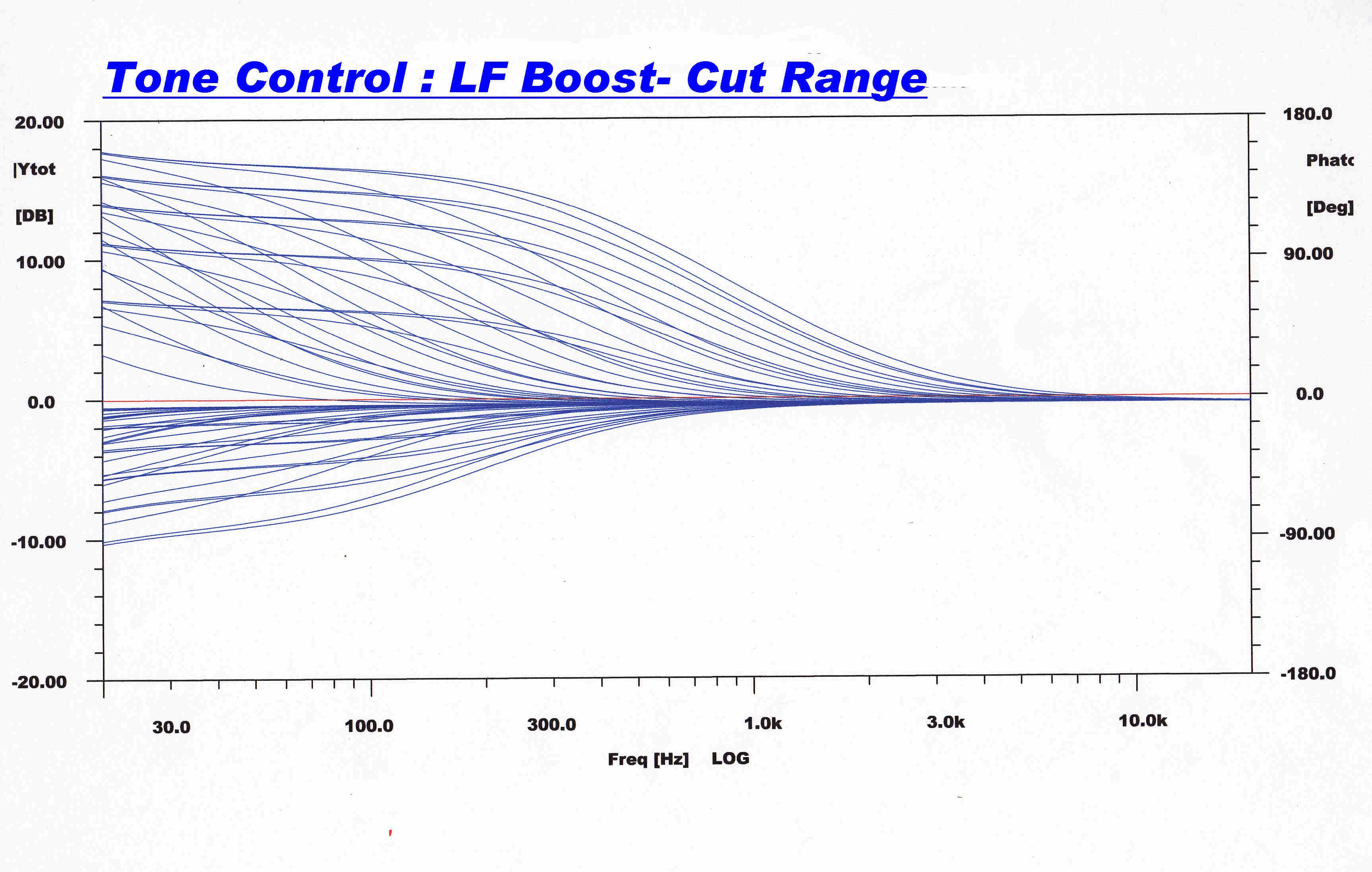
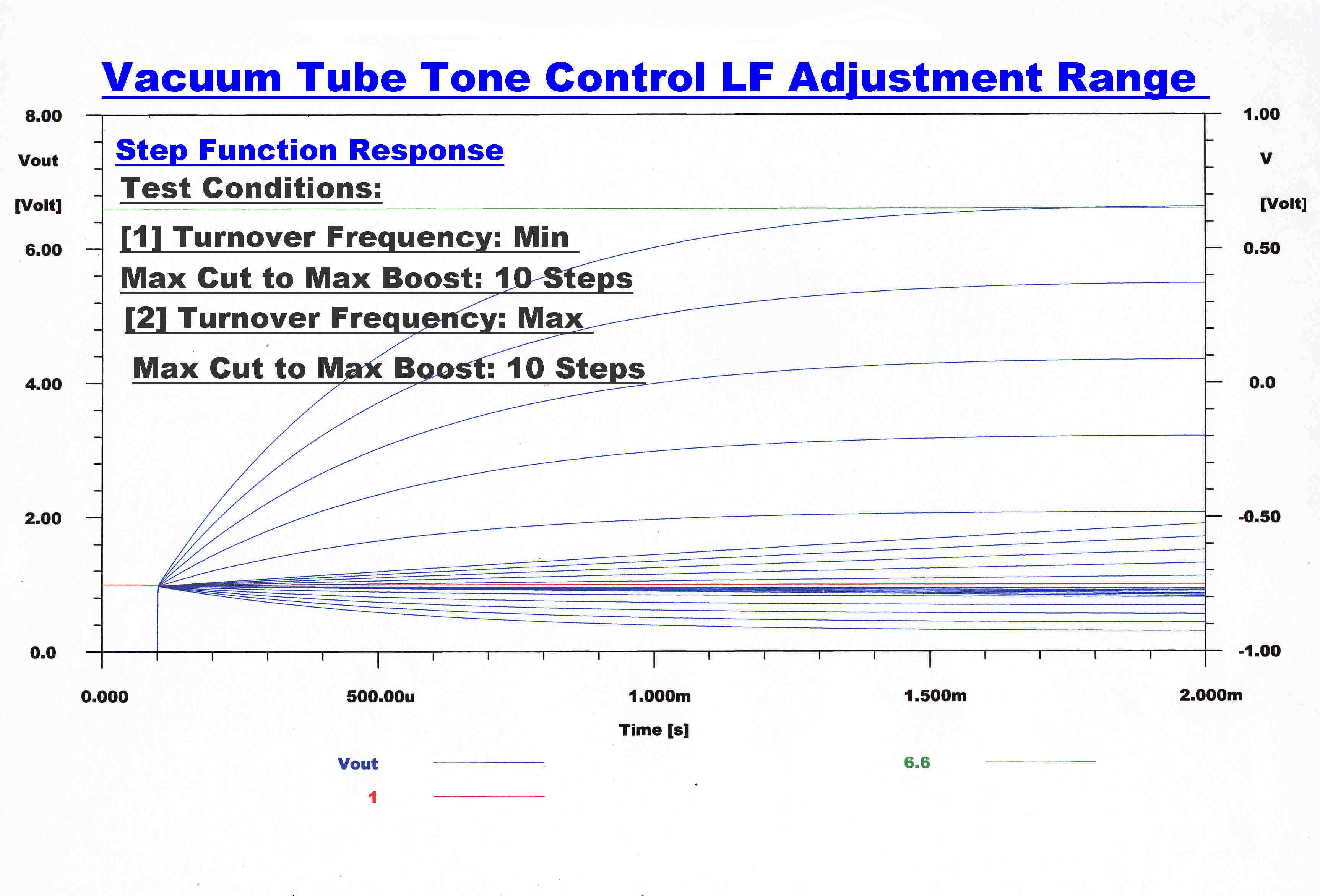
The maximum boost is 17.3db.
The maximum cut is -10.6db.
In the boost position the response increases ultimately to 7.333.
In the cut position the response decreases ultimately to 0.2962.
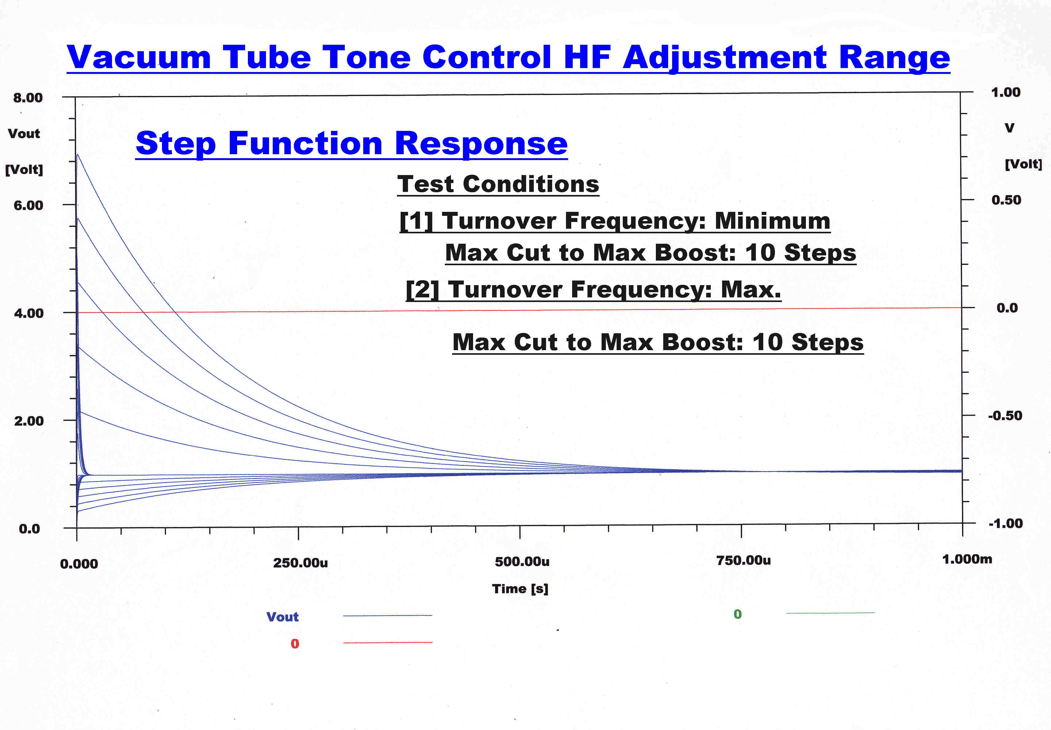
The maximum boost is 17.3db.
The maximum cut is -10.6db.
In the boost position the maximum initial step is 7.33.
In the cut position the minimum initial step is 0.296.
SET UP
Initial Setup
Apply a 1KHz. 1 volt peak square wave to the input.
(1) Monitor the signal on the cathode of VT2.
Adjust the 1/5pF trimmer in the grid of VT2 for best rise time without overshoot.
(2) The 4.333k resistor shown in the plate of VT3 is best replaced by
a 3.9k resistor in series with a 1k pot.
Monitor the signal on the cathode of VT6.
Place both boost - cut pots in the middle position.
Adjust the 1k pot until the top of the square wave goes to zero.
Adjust the padder capacity until the transient at the front of the square wave
is at a minimum.
(3) Monitor the signal across the 100k volume control.
Adjust the 1/5pF trimmer in the grid of VT8 for minimum
rise time with no overshoot.
(4) Monitor the output and adjust the 1/5pF trimmer in the grid of
VT11 for minimum rise time with no overshoot.
A short description of a preamplifier - disc equaliser and tone control
from 1955 follows.
The CE and MBH pickups described in the preamplifier section were used
and provided a much higher output than modern moving magnet stereo cartridges.
The equipment is still in use. The electrolytic capacitors have been replaced :
the tubes are original.
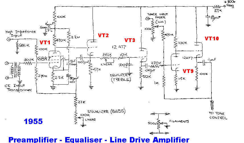
The preamplifier consists of VT1 and VT2.
Bass boost equalisation is achieved with the 3nF AC coupling network
in the feedback loop.
The lower turnover frequency is 260 Hz.: the upper 630Hz.
High frequency equalisation is achieved with the R-C network between VT2 and VT3.
The turnover range is from 1137Hz. to 31.8KHz.
For discs requiring no preemphasis correction the turnover is set to 31.8KHz.
The line output amplifier is on the same chassis as the preamplifier but is deiven
by the tone control, not the preamplifier.
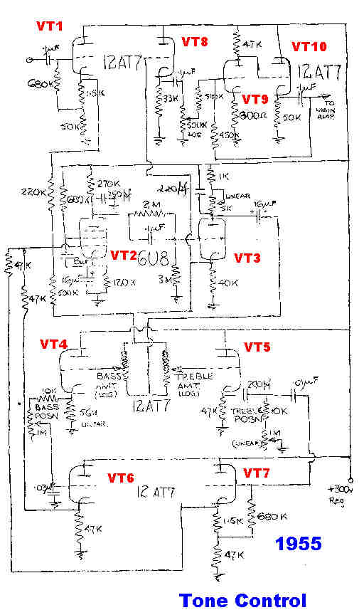 VT1 is a unity gain cathode follower.
VT2 and VT3 form a high gain feedback amplifier.
Variation in response is obtained by varying the amount
of feedback around this amplifier through two R-C low pass and
high pass networks.
Cut is achieved by increasing the feedback : boost by applying positive
feedback to cancel out some of the existing negative feedback.
The phase splitter and 100k Log potentiometers produce a signal beteeen
x1 and x(-1/9) of the feedback amplifier output as outlined in the main
text above.
VT4,VT5,VT6 and VT7 form unity gain buffers for the R-C networks.
Note: The preamplifier and tone control have been in constant use since 1955.
The electrolytic capacitors have been changed - but all the tubes are original.