WESTERN ELECTRIC WE4A PICKUP
CONTACT : COMMENTS AND QUESTIONS
back/home
 The origins of most electro-mechanical devices rely on ideas inspired either
by Maxwell or Rayleigh, so it is interesting to enquire why the first successful
electrical disc cutter and the accompanying WE4A pickup were developed in the USA
and not Britain.
The origins of most electro-mechanical devices rely on ideas inspired either
by Maxwell or Rayleigh, so it is interesting to enquire why the first successful
electrical disc cutter and the accompanying WE4A pickup were developed in the USA
and not Britain.
At the time of his death on 5th of November 1879, Maxwell's equations had been solved for the behaviour of
electromagnetic waves in free space. The solution of two outstanding problems remained:-
[1] The generation of electromagnetic waves from accelerated ( ie oscillating ) charges.
[2] The propagation of electromagnetic disturbances (signals) along cables.
*Maxwell:James Clerk Maxwell: A Treatise on Electricity and Magnetism.
First published: 1st February 1873
*Rayleigh:Baron Rayleigh or John William Strutt: The Theory of Sound
First published: 1877
 The first and most difficult problem was solved by George Francis FitzGerald of
Trinity College Dublin.
The first and most difficult problem was solved by George Francis FitzGerald of
Trinity College Dublin.
"On the Quantity of Energy Transferred to the Ether by a Variable Electric Current"
Transactions of the Royal Dulin Society: 19 November 1883.
The second problem was solved by Oliver Heaviside ( 1850 - 1925 ), a highly eccenctric
mathematician and engineer of genius working outside the British establishment.
He rediscovered a version of the Laplace Transform which came to be named "Heaviside Operational Calculus"
His research into propagation along transmission lines would eventually lead to Harrison's cutting head and
and its complement - the WE4A.
Heaviside's work showed the importance of inductance in the transmission of signals along a line.
An increase in inductance increases the characteristic impedance of the line, so that the
the resistance of the conductors becomes less significant and the attenuation lower. High voltages
with corresponding lower currents are employed in power transmission for the same reason.
Zo = [L/C]1/2.
Zo = characteristic resistance.
L = inductance per unit length.
C = capacity per unit length.
 Sir William Henry Preece (1834 - 1913) was first Electrician and
Engineer - in - Chief of the British Post Office.
Sir William Henry Preece (1834 - 1913) was first Electrician and
Engineer - in - Chief of the British Post Office.
Sir William did not believe in the existence of self inductance.
In 1888 he described it as "just a lot of bugaboo!"
As a consequence, Heaviside's ideas were not applied to transmission problems in Britain,
but were forced across the Atlantic where they were taken up by Professor Michael Pupin
at Columbia university and then, eventually, by Bell Labs.
Pupin greatly improved American telephony by winding a thin steel ribbon around cable to increase the
self inductance. This was found to be very expensive, and, to decrease the costs, an approximation
was made by adding lumped inductance along the line at regular intervals.
This worked fine up to a critical frequency where the lumped nature would manifest itself
and reject all higher frequencies.
This apparent failure at high frequencies proved the germ for progress, not only in telephonic
transmission, but also for disc recording.
It suggested to the fertile minds at Bell that repeated or iterative networks could
be made flat or transparent up to a certain frequency and above this frequency to sharply
reject all others.
Filter theory was born.
From the clue described above, Campbell, Zobel and Carson working at Bell developed
classical filter theory. Networks transparent to any prescribed range of frequencies could be
designed at will.
Immersed in such a milieu, Maxfield and Harrison realised that this was the way forward
in disc recording, since any mechanical system can be expressed as an analogous electrical network.
For instance:-
Force converts to voltage.
Velocity converts to current.
Mass converts to inductance.
Compliance or springiness converts to capacitance.
Converting the other way, there does not seem to be any mechanical equivalent for mutual inductance.
The route to the Western Electric cutter and the WE4A described above is marked by
two classical papers:
(1) " Wave Propagation over Non-Uniform Cables " by M.I.Pupin
Trans AIEE,Vol. 17, 1900
(2) " Theory and Design of Uniform and Composite Wave Filters "
by Otto J. Zobel B.S.T.J. Vol 2 No1 pp 1-46 1923
Norton, the Norton of Norton's Theorem, had the desk next to Harrison at Bell and his influence on the development of network theory and of electro - mechanical equivalents should never be underestimated.
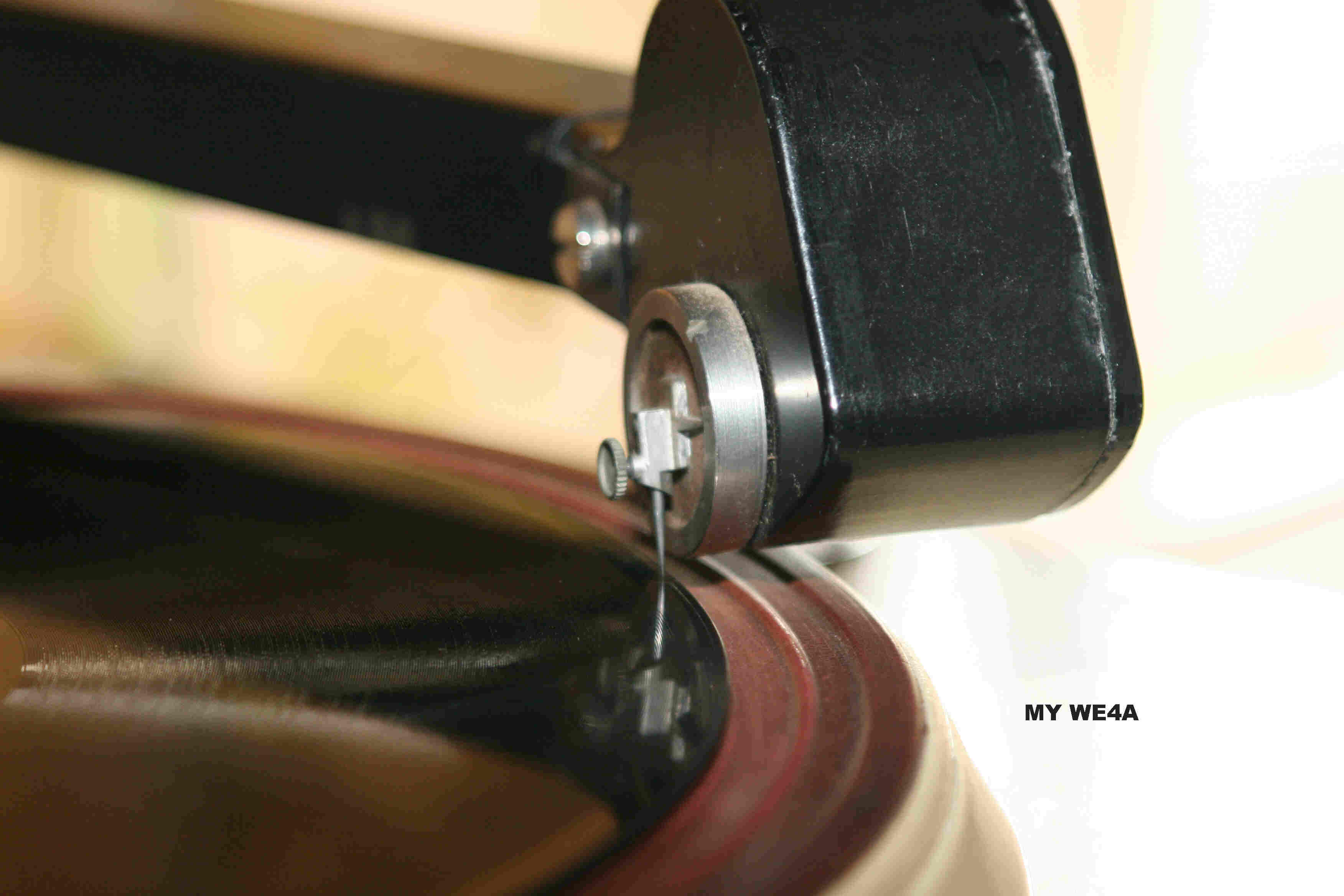
BRIEF DESCRIPTION of THE WE4A
============================
 In early pickups the needle usually was coupled to a large iron armature of great mass.
The designer of the WE4A realised that the required signal was already present in the deflection
of the centering spring.
All that had to be done was to read this deflection in some way.
In the WE4A the centering spring is made into a circular steel plate - reinforced in the centre so that
it bends anti-symmetrically.
As the needle deflects to the right, the bottom of the plate deflects inwards and the top outwards.
The plate is made part of the wall of a sealed enclosure filled with oil.
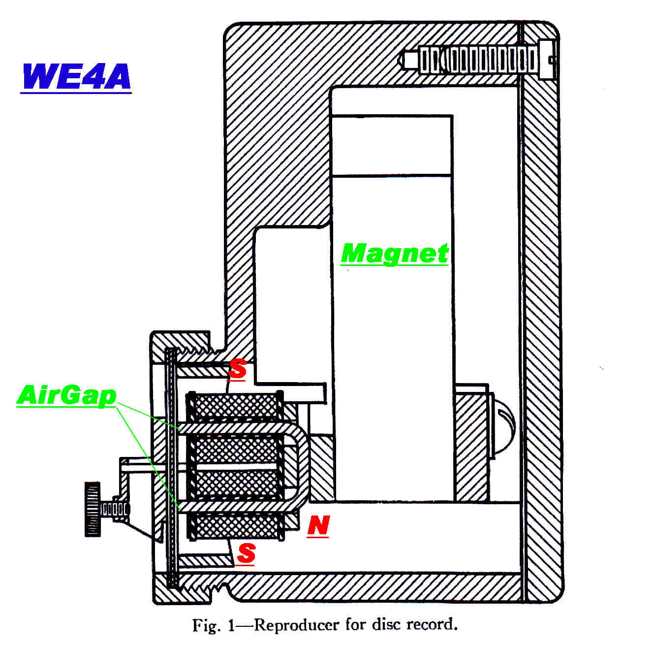 The plate forms part of a magnetic circuit, so the air gap at the top is increased and the gap
at the bottom decreased.
The plate forms part of a magnetic circuit, so the air gap at the top is increased and the gap
at the bottom decreased.
This means that the magnetic flux is diverted either into the
top or bottom coil, and so induces a voltage into these coils.
The symmetry reduces even order distortion.
The total flux around the magnetic circuit is constant.
Only the iron under the two coils experiences a change in flux.
The pickup, then, is a true variable reluctance system.
It has a constant velocity response.
The plate forms part of a sealed enclosure filled with oil.
This has two functions:-
(1) The oil against the plate produces mechanical damping.
(2) The oil covering the windings protects them.
For the time of its design (1925 - 1926), the pickup was a lightweight.
The needle point weight on mine is 79.9 gms.
Since it uses no rubber in its design, the characteristics remain constant over great lengths of time.
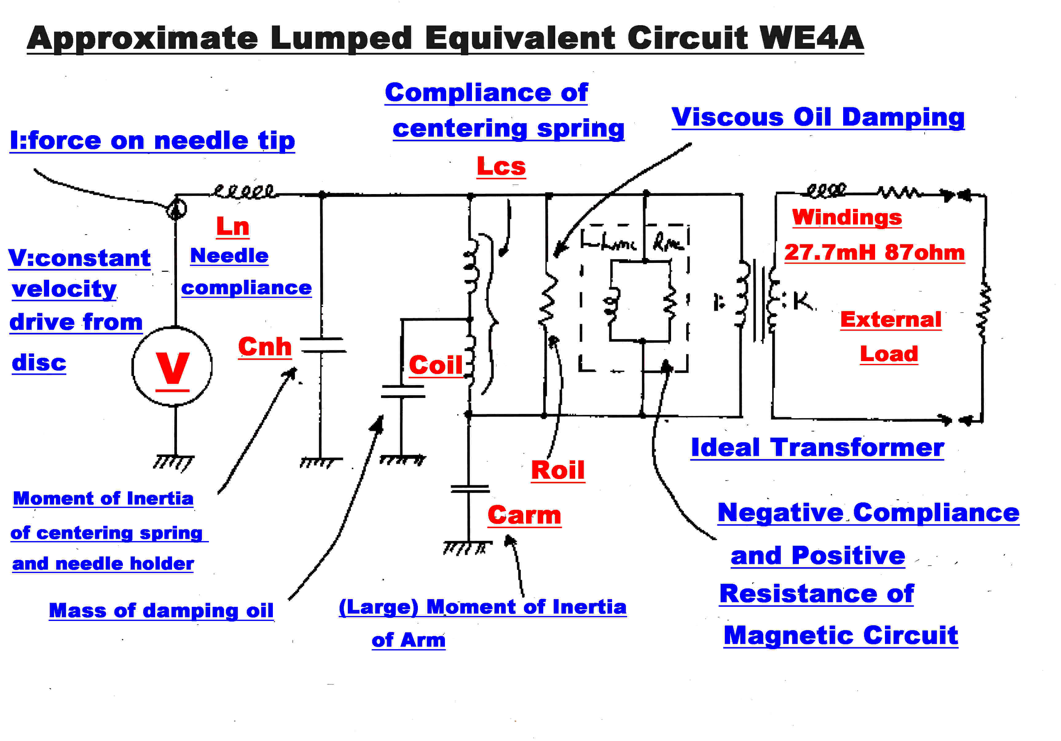
Note: Because the WE4A is a magnetic transducer, the following
electro-mechanical equivalents have been adopted:-
Velocity (v) --> Voltage (V)
Force (F) -----> Current (I)
*Compliance (U) --> Inductance (L)
Mass (M) --> Capacity C
**Viscous Force Constant (J ) --> Resistance (R)
*Compliance = ( Elastic Deflection )/( Force ) = 1/S where S is the spring constant.
**Viscous Force Constant (J) = ( velocity)/(viscous force)
It is assumed that the pickup is tracking the disc, so that the needle tip velocity (Voltage)
is determined entirely by the disc. It can therefore be represented as an independent
voltage generator.
APPROXIMATIONS IN DERIVING THE LUMPED EQUIVALENT
The lumped equivalent circuit can, at best, give only a rough approximation
to the performance of the WE4A, but it does explain the general behaviour and the dependence
of the response on the compliance of the steel needle.
The following complications arise in the development of the equivalent circuit:-
[A] Oil must flow in and out of the magnetic gap, so the viscous damping has a capacitive
as well as a resistive component.
[B] The viscous damping is distributed along the retaining spring.
[C] The retaining spring, in the form of a circular plate, probably has significant
distributed mass.
[D] The needle clamping screw acts as a mass supported by a short cantilever, and
so should be represented as a series tuned circuit across the main moment of inertia Cnh.
In the equivalent this is lumped in with the moment of inertia of the needle holder.
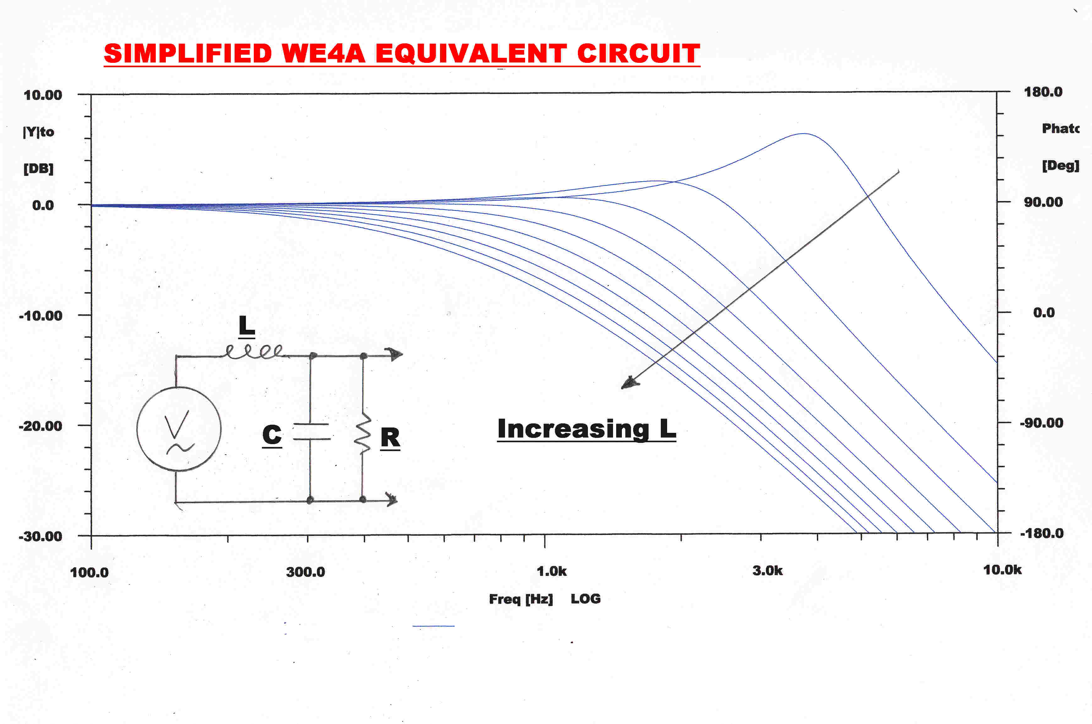 SIMPLIFICATION OF THE LUMPED EQUIVALENT
[A] Ln and Lcs can be regarded as an inductive voltage divider to give a
Thevenin equivalent input voltage generator of Vin[ Lcs/( Ln + Lcs ) ]
[B] The equivalent output inductance, Lout, of this generator is Ln//Lcs
ie: Lout = (Ln x Lcs)/( Ln + Lcs )
[C] The WE4A equivalent then reduces to the simple resonant system shown in the above diagram.
Ln represents the compliance of the steel needle.
This can be regarded as a cantilever of circular cross section for which the compliance U
is given by:-
U = K l3/d4
K = constsnt
l = length of needle
d = diameter of needle
The length of both "loud" and "soft" steel needles is about 16mm.
The diameter of "loud" needles is about 1.5mm: the diameter of "soft" needles is about 0.8mm.
This inplies that the compliance of soft needles is much greater than that of loud needles,
so that:-
[1] There is greater attenuation in the inductive divider Ln, Lcs. (Since Ln is now very large)
[2] The output inductance of the equivalent Thevenin generator increases giving rise to high
frequency attenuation as shown in the steady state frequency plots above.
If CL = compliance of a loud needle and CS the compliance of a soft needle
then:-
CL/CS = (1.5/0.8)^4 = 12.36 - a large ratio.
In some needles the compliance depended on the direction of loading , so that they could be "loud" or "soft"
depending on the angle of mounting in the pickup.
A section of the cylindrical needle was hammered flat into a flange.
If the sharp end of the flange pointed to the turntable spindle, the compliance was low - giving a "loud" needle
with good high frequency response. Turning the needle by 90 degrees gave a high compliance and a "soft" needle.
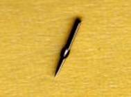 A picture of such a needle is shown on the right.
Picture courtesy of the Vintage Wireless and Gramophone Club of Western Australia.
WARNING
There is more know-how in the manufacture of steel gramophone needles than is often realised.
THEY ARE NOT SIMPLY SHARPENED PIECES OF STEEL.
Large bags of needles were tumbled for many hours. This produced the following qualities:-
[A] A curved edge on the point.
[B] A high polish.
[C] A hardened point.
This process has not been performed on many of the cheap needles sold today, with the consequence that
about a third of the way into a 10 inch 78 the point goes blunt with horrendous tracing distortion and poor
high frequency response.
The conclusion is that soft needles not only decrease the signal level, but act as a tone control to give high frequency attenuation.
In the equivalent circuit the needle tip forces are represented by
the current in the inductor Ln.
The following general conclusions can be drawn from the equivalent:-
[1] Needle tip forces are at a maximum when the inductors resonate with Cnh
to give a peak in the response.
They are limited only by the oil damping resistance.
In acoustic reproducers the horn presents a suitable damping resistance.
In electrical reproducers the external resistive load does not provide sufficient damping,
so extra damping has to be introduced. This is usually in the form of lossy rubber.
In the WE4A oil damping is used, and this accounts for the long life and stability of
characteristics of the WE4A.
[2] The inductors Ln and Lcs can also resonate with the large capacity representing
the mass of the pickup head and arm. This also increases the needle forces
at a much lower frequency.
[3] With "soft" needles Ln is large and the current through it decreases. "Soft" needles
therefore greatly reduce needle tip forces.
Recording levels have increased since the WE4A was introduced in 1926. It is found
the the WE4A tracks modern heavily cut discs with low distortion.
A combination of needle wear and reduced track velocity increases the tracing distortion
towards the inside of a disc. To minimise this effect most transcription discs
were inside start.
The output of the WE4A on old worn discs is much cleaner than that from a modern
light weight cartridge. The effect is purely mechanical.
Initially the steel needles grinds to the shape of the groove, and the weight of the WE4A
ensures that the needle stays in the groove and is not buffeted by dirt and steel particles.

Both curves have been normalised at 1KHz. to emphasise the attenuation
of high frequencies with "soft" needles.
The test results follow the general trend predicted by the lumped equivalent circuit.
The pickup was designed for use with "loud" needles, so the 3db peak at 4KHz is intentional.
It was said to render the reproduction more lively.
The output level was high and the output impedance low, so the WE4A can drive a long cable
to the amplifier. Optical sound heads with an inbuilt amplifier were designed to produce an output
comparable to the WE4A.
The folowing tracks illustrate the quality of reproduction with the WE4A.
WE4A DETAILS
Design Year: 1925
Tracking Weight 79.9 gms.
Transducer: Magnetic - Variable Reluctance.
Acoustics and early electricals were played with a medium compliance needle:
Diameter: 1.32mm.-------Length: 16mm
Electricals with better surfaces were played with a low compliance needle:
Diameter: 1.65mm.-------Length: 16mm.
Playback Equalisation:
Acoustics: Constant velocity.
Electricals: Constant velocity above 250Hz. :: Constant amplitude below 250 Hz.
Filtering:
All filtering 6th order maximally flat.
High pass:
50 Hz. for electricals.
150 Hz. for acoustics.
Low pass:
4.5 KHz for acoustics.
6 KHz for electricals.
DISC DETAILS
[1] IN THE SHADE OF THE OLD APPLE TREE
( Williams and von Alstyne )
Joe Daniels and His Hotshots in "Drumnastics"
©E 7242 - 1
Parlophone
Disc recorded using the Blumlein cutter, probably at Abbey Road. 1935
Joe Daniels: born 1908, Zeerust/Transvaal, South Africa.
Drummer with Harry Roy 1931 - 1937
Formed Hotshots in 1935.
This disc is from the ABC record library in Brisbane. Although it carries over 80 years of wear
and tear, it probably gives a good idea of the broadcast quality from the ABC
in the thirties and forties when the WE4A was the standard studio pickup.
In the late thirties and into the forties many of the national transmitters employed over
30db of envelope feedback, so, overall, the broadcast quality was good.
Note the increase in tracing distortion towards the end of the track as the steel needle wears
and the track velocity decreases.
Inside start discs greatly reduced this distortion.
To listen to the track, press
In the Shade of the Old Apple Tree
[2] NOLA
( Felix Arndt )
Les Paul
Multitrack Guitar
MX42049 5860
Red Capitol
Les Paul: born Lester William Polsfuss 9 June 1915.
Pioneered the solid body electric guitar and multitrack recording.
First disc to disc, then using 8 track tape made by Ampex.
Although designed in 1925 when the recording level was low, the WE4A will track heavily modulated
78 discs of the late era as illustrated below.
To listen to the track, press
NOLA
THE 1911 HIT PARADE: Early Acoustics.
==================================
[3] The Bad Girl of The Family
Whit Cunliffe
Sung by Mr. Arthur Osmond
Recorded in London: Reproduced in Linden
Favorite Record
Serial N307a
Matrix 2662 - b 1 - 67165
Recorded 10/04/1911
Monday 10 April 1911
Note: This disc came from a sheep station (ranch) in the West of Queensland,
It was probably a hit with the Jackeroos (cowboys) in 1911.
It was covered in clay and grit, which had to be hosed off.
It is amazing that the WE4A managed to lift a relatively clean signal
from such a surface.
The WE4A proved to be a superb device for playing worn acoustic lateral discs.
A modern light weight pickup responds to every obstacle on the disc such as small
pieces of grit and steel. Because of its weight, the WE4A simply ploughs through them.
Further, the groove shape and size is highly variable, The steel needle rapidly grinds
to fit the groove as was intended with the old discs.
To listen to the track, press
The Bad Girl of the Family
Roughly thirty three years later on the same theme, but with some
improvement in recording quality, we have:
[4] Our Fanny's Gone All Yankee
George Formby with Ukulele and Orch.
©AR6534-2 Cat. G24937
Regal Zonophone [red/green]
Recorded November 1944
To listen to the track, press
Our Fanny's Gone All Yankee
Here is an example of the WE4A negotiating a heavily worn disc from the thirties.
On discs with a surface which is no longer flat, but has become rippled, the WE4A does
introduce some low frequency rumble. This is noticeable on this disc and is very
characteristic of the WE4A's performance.
[5] Voices of Spring
Erna Sack
German Opera House Orchestra Berlin
Conducted by Dr. Hans Schmidt - Isserstedt
D 020724 0 E0171
Note: The sustained note at the end of this track is 14 Seconds
long and has a measured frequency of 1.455KHz.
The waveform is close to sinusoidal. The third harmonic is
32db below the fundamental.
It is interesting to evaluate which note this is in the musical scale.
In the Western 12 tone system the frequency of any note is given by:-
f = fo x 2^( n/12)
where f is the frequency in Hz.
fo is the reference frequency.
n the number of intervals between them.
So that: n = (12 x log( f / fo ) )/( log( 2 ) )
In the 30s when this disc was recorded :
Middle C = fo = 256 Hz.
f = 1455 Hz
So that:
n = 30.08
Considering the errors in orchestra tuning, the singer's sense of pitch,
and the tolerance on recording and reproducing turntable speeds,
it seems close to a miracle that n comes out so close to an integer.
In other words Erna has nailed it right in the middle.
Two Cs above middle C occupy 24 intervals, so that the note is 6 intervals above this or F sharp.
To listen to the track, press
Voices of Spring
The WE4A is useful in recovering a signal from a disc with extreme wear : Here - The Teddy Bears' Picnic
This 78 is out of the ABC's (The National Broadcaster ) record library in Alice street Brisbane. It may well have been there since 1932.
It was extremely popular - hence the wear.
Note the rise in distortion at the end due to wear of the steel needle and also to wear on the disc.
[6] The Teddy Bears' Picnic
The Rhythmic Troubadours : This was the name given to Henry Hall and The BBC Orchestra on Australian Pressings - Reason not known
Vocalist: Val Rosing
Regal Zonophone : Matrix: MA5642
Recording Date: Wednesday 28 September 1932
Recorded at Abbey Road with the Blumlein Moving Coil Cutter.
To listen to the track, press
Teddy Bears' Picnic
This is the reverse side of the Teddy Bears' Picnic and so all the remarks made above apply.
The WE4A is useful in recovering a signal from a disc with extreme wear : Here - Hush, Hush. Hush, Here Comes the Bogey Man
This 78 is out of the ABC's (The National Broadcaster ) record library in Alice street Brisbane. It may well have been there since 1932.
It was extremely popular - hence the wear.
Note the rise in distortion at the end due to wear of the steel needle and also to wear on the disc.
[7] Hush, Hush, Hush. Here Comes the Bogey Man
The Rhythmic Troubadours : This was the name given to Henry Hall and The BBC Orchestra on Australian Pressings - Reason not known
Vocalist: Val Rosing
Regal Zonophone : Matrix: CA 13048
Recorded at Abbey Road with the Blumlein Moving Coil Cutter.
To listen to the track, press
Hush, Hush, Hush, Here Comes the Bogey Man
This cutter was one of the masterpieces of electro-mechanical design of
the 20th century.
It also had a profound effect on the shape of the century with the enormous improvement
in the quality of disc recording and the introduction of film sound on disc.
The realisation of the recorder was made possible by:-
[1] The development of classical filter theory at Bell.
[2] The realisation of the dynamic equivalence between electrical and mechanical systems.
ELECTRO-MECHANICAL EQUIVALENCE
Linear differential equations with real constant co-efficients govern the
dynamic behaviour of both electrical amd mechanical systems.
If an electrical system is designed to have the same governing differential equation as
a mechanical system, then one will be the exact analog of the other.
With a magnetic transducer, force is produced by current and voltage is produced by velocity.
It is then natural to equate these variables.The link between the two then becomes an ideal
electrical transformer with the transformer ratio determined by the transducer constants.
It is possible to get an equivalent with the variables reversed, but then the transducer is
represented by a gyrator with a much indreased difficulty in interpretation.
With a piezo-electric transducer, force is produced by voltage and current is induced by velocity,
so it is natural to equate these.
MAGNETIC TRANSDUCER |
PIEZO-ELECTRIC TRANDUCER |
|
Put:- |
Put:- |
|
I = C dV/dt |
V = L dI/dt |
|
V = L dI/dt |
I = C dV/dt |
|
V = R I |
I = G V |
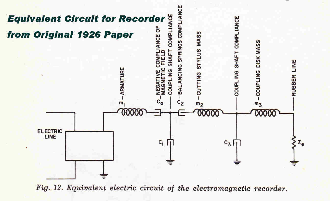 The original paper on the cutting head was:-
Methods of High Quality Recording and Reproducing Music and Speech
based on Telephone Research.
Bell Telephone Journal: July 1926 pp 493 -- 526.
The recorder had a magnetic transducer, but the equivalent circuit
included in the paper uses equivalents appropriate to a piezo-electric transducer.
Consequently, much of the equivalent is represented by a nameless block.
It also difficult to relate the circuit to the dynamic behaviour of the
mechanical system.
The complete equivalent circuit including the driving amplifier, and using appropriate
equivalents, is given below.
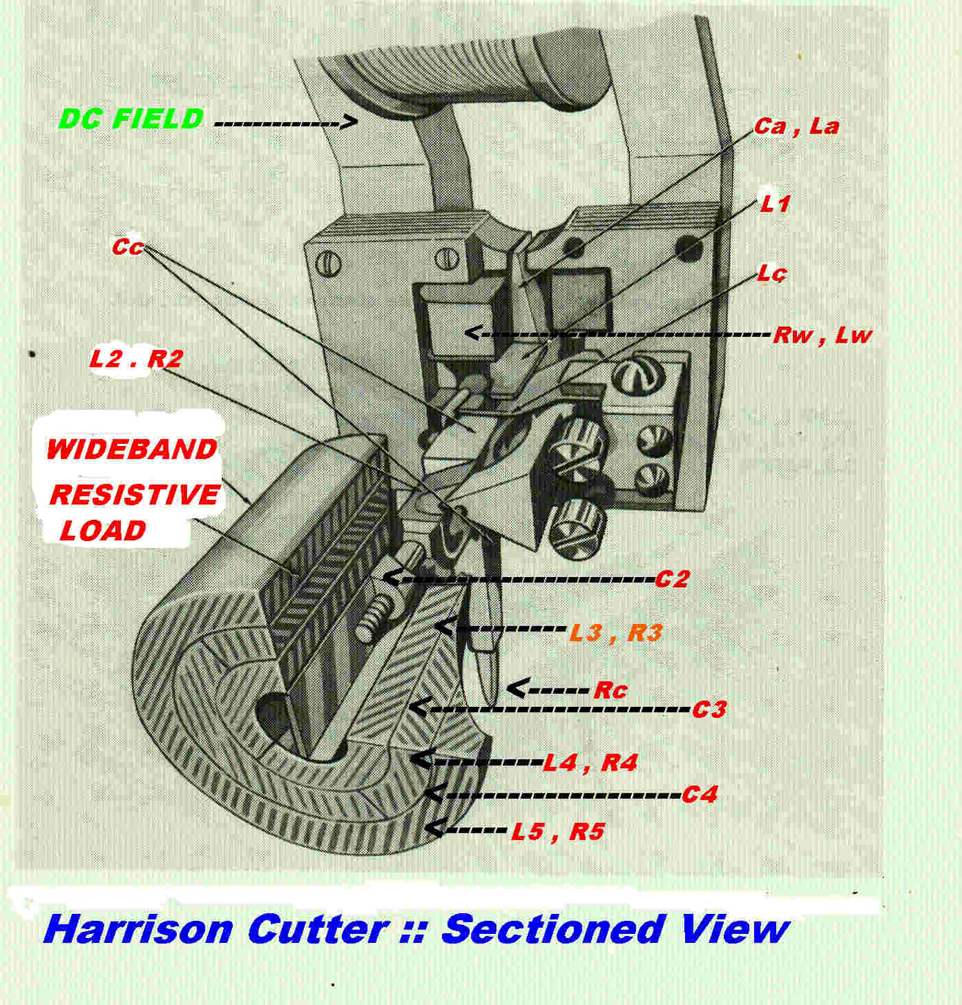 A sectioned drawing of the cutter is shown opposite.
Each mechanical element is tagged with its electrical eauivalent.
The required output is the velocity at the tip of the stylus. The maximum displacement
for a 78 disc is +(-) 2 thou. of an inch, so, for the small angles involved, angular
displacement translates into linear displacement.
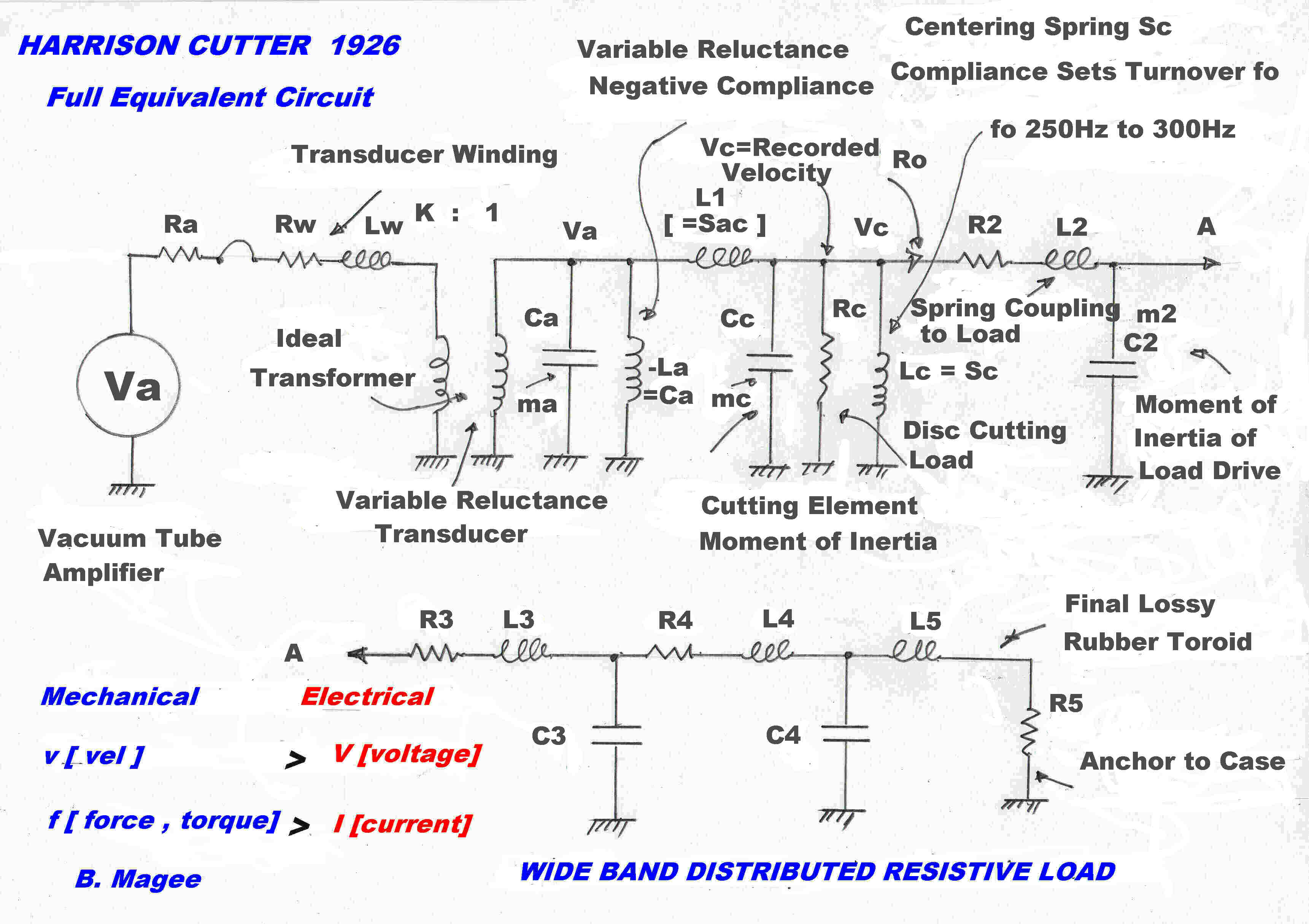 The full equivalent circuit using equalities for a magnetic transducer are shown opposite.
If the two inductances and resistance to earth ( -La, Lc and Rc ) are removed, the circuit
reduces to a classical low pass constant k filter terminated at the far end.
Over the pass band the filter reflects a constant resistance, Rf, into the primary of the transformer,
so that the total primary resistance is Rtot = Ra + Rw + Rf .
If the winding inductance of the transducer, Lw, is not to cause high frequency attenuation, then
the resistance must be greater than the inductive reactance at the cutoff frequency fc.
ie: Rtot > 2 Π fc Lw
The filter, then, is driven from a resistive impedance.
We can now observe that :-
[1] The filter is a classical constant k low pass filter.
[2] The filter has three sections: two half L sections at the end and a full T section
in the middle.
[3] The filter is terminated at the receiving end and driven from a resistive impedance
at the sending end.
We now discuss the action of the three elements which we removed from the equivalent
circuit to produce a classical constant k low pass filter.
 The required output is not taken from the terminating load but from the centre of the
middle section.
The required output is not taken from the terminating load but from the centre of the
middle section.
The voltage appearing across Cc represents the required output, the angular velocity of
the cutting stylus.
In lateral recording the dynamic forces at the stylus tip are proportional to velocity.
They therefore appear as a resistive load across Cc.
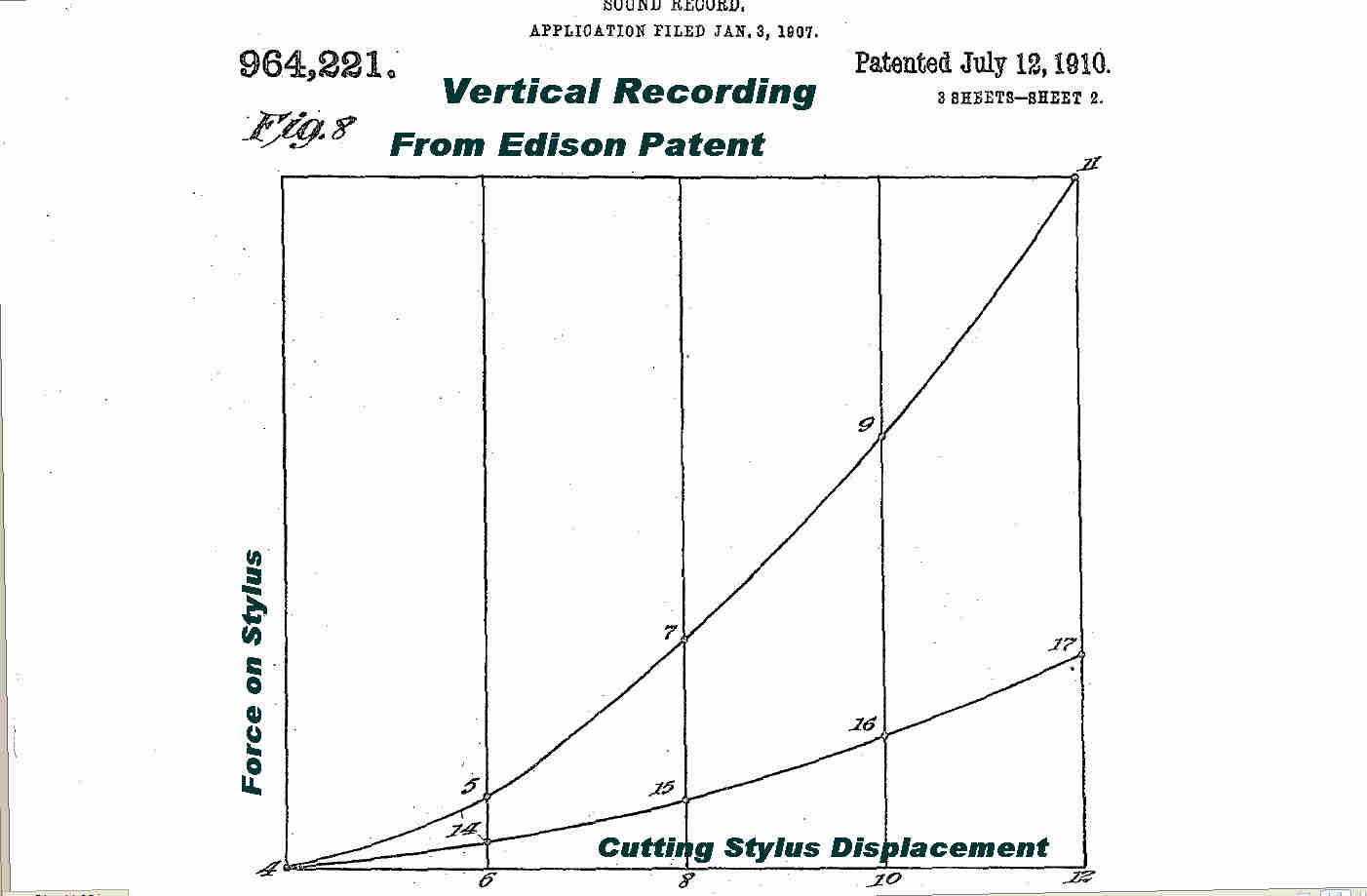
Note: In vertical recording the forces are highly non-linear.
A good account of this is given in Edison patent No.954,221 July 12 1910.
It is important that the cutting load Rc be much greater than the characteristic
resistance of the filter for two reasons:-
[A] It is desirable that the recorded signal be independent of the characteristics of
the master disc.
[B] The cutting process produces random forces at the tip of the cutting tool. These excite
movement which will be cut back onto the disc as noise.
Keeping Rc high compared with the filter impedance minimises this effect.
With constant velocity recording the displacement is inversely proportional to frequency,
so that this becomes excessively large at low frequencies. The introduction of
a 6db/octave slope in the velocity response at low frequencies results in constant
amplitude recording.
This is conveniently introduced by the centering spring Lc.
At low frequencies this shunts the signal to earth.
The turnover frequency fc is set by the time constant of the total driving resistor R//
and the inductor Lc.
T = Lc/R// :: fc = 1/2 Π T
Note that the turnover frequency is set by the strength of the centering spring:
not by a network in the amplifier.
At low frequencies the recorder reduces to a very simple system.
The curerent drive is independent of frequency, and so produces a constant torque
applied to the centering spring: giving a constant displacement
and so constant amplitude recording.
Imagine the DC field of the recording head energised with
the audio input left open.
If the magnetic vane marked ( Ca La ) is displaced from its central position, magnetic
poles are induced on its tip, and these produce a torque in the DC field.
The torque is proportional to angular deflection, but is of opposite sign to that
produced by a spring.
It therefore must be represented by a NEGATIVE compliance.
The elements Cc and La are in parallel so the total susceptance y(p) is given by:-
y(p) = pCc - 1/pLa
In the steady state this yields:-
y(i ω) = i ωCc[ 1 + ( ωo/ω )2 ]
where ωo = 1/√LaCc
No data was given to calculate ωo , but it is assumed the squared term
is very small at high frequencies approaching cutoff, and so has little effect on
the constant k filter action.
Note: There are accounts of the pole piece hitting and sticking to the stationary
laminations on very high recording peaks.
 The design of electrical wide band resistive loads is difficult: the design of
wide band mechanical loads is even more difficult.
The design of electrical wide band resistive loads is difficult: the design of
wide band mechanical loads is even more difficult.
Wire wound resistors exhibit inductance and the resistance changes with frequency
due to skin effect.
Rubber exhibits histeresis and so resistance along with compliance. The histeresis changes
with frequency to mimic the complications of skin effect in wire wound resistors.
This technique is illustrated in the bottom part of the cutter equivalent circuit.
To realise a wideband load of resistance Ro up to a frequency fo:-
[1] Take a constant k section R3 L3 C3
[2] L3 has a series resistive component R3 - a small fraction of Ro
[3] Design L3 C3 to have a characteristic impedance Ro - R3 and a cutoff frequency fo
[4] In the next section L4 C4 has a characteristic impedance of Ro - R3 - R4 and a
cutoff frequency of fo
[5] Eventually a termination of 0 ohms will be reached and the output operated into
a short circuit.
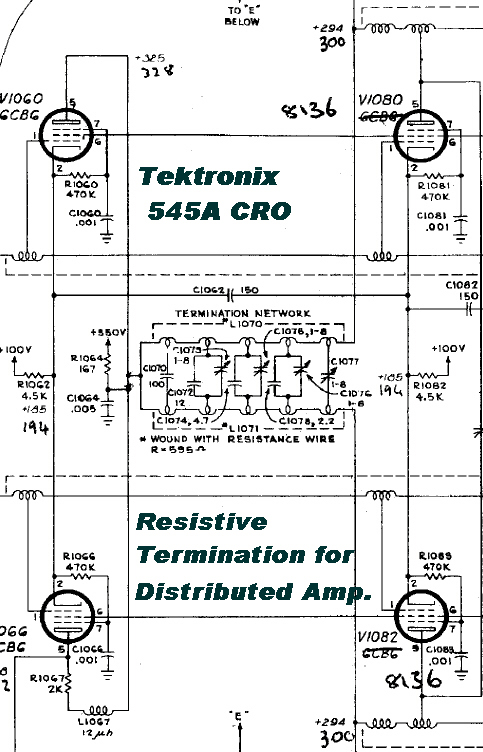
The technique was used in the fifties to terminate the output lines
in distributed amplifiers.
An example used in the Tektronix 545A oscilloscope is given opposite.
It is interesting to note that the Bell engineers ( probably Norton ) were aware of this
technique in the twenties and used it first in a mechanical analog form.
The lumped line described above approaches a transmission line as
the size of each element is decreased.
The characteristic impedance of a lossless uniform line is purely resistive, and so a line
of infinite length would act as an ideal load.
Lines in the real world need not have an infinite length.
The characteristic impedance of a uniform transmission line closely approximates a resistance
if the attenuation per wavlength is not too great.
If the line is of sufficient length, so that the reflected wave is small compared with
the transmitted wave, then the input impedance will still remain largely resistive.
Further, it does not matter if the trmination is a short or open circuit.
A lossy rubber transmission line replaced the lumped equivalent in the final form of the
cutting head.
Its response was more even than the lumped line and it was easier to manufacture.
Unfortunately the properties of rubber are time and temperature dependent.
This was a disadvantage in an otherwise brilliant design.
The application of motional negative feedback by Bell rendered mechanical damping
unnecessary and produced a design with an excellent dynamic response.
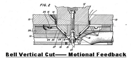
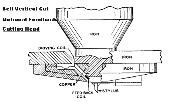 Bell were the first to apply motional feedback to a vertical cutting head in the
Thirties. Sectioned drawings of the cutter are shown.
Bell were the first to apply motional feedback to a vertical cutting head in the
Thirties. Sectioned drawings of the cutter are shown.
Note that no damping material is required in the head: the motional feedback has complete control
over the movement of the cutting stylus.
Two of the main difficulties in applying motional feedback are:-
[1] Preventing inductive pickup by the motion sensing coil from the main driving coil.
[2] Ensuring the motion of the pickup coil and the cutting stylus are the same.
Coupling between the two coils is reduced by a thick copper ring shield.
The pickup coil is attched as close as possible to the cutting stylus to ensure
they share the same motion.
The mass and compliance of the moving system produce high Q mechanical resonance at about
700 Hz. This produces a transfer function stable under a large degree of feedback.
The feedback flattens the curve over the complete audio spectrum.
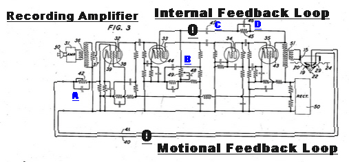 The recording amplifier for the motional feedback cutting head is shown on the right.
The transfer function of the forward path is modified by an internal feedback loop
with elements B,C,D.
The transfer function of the motional feedback path is modified by the network A.
In a vacuum tube the transfer characteristics of the control, screen, and suppressor grids
are different non-linear functions, and it is not good practice to apply the input and
feedback signal on different grids.
This general principle is violated twice in this amplifier:-
[1] The internal feedback is applied to the screen of pentode 33.
[2] The input signl is applied to the suppressor of pentode 32.
 The circuit technique criticised above comes from a patent by Wiebusch.
Note that when a signal is applied to different grids, a component of plate current
is the product of the two - not a desirable state of affairs in a linear system.
The following hill and dale tracks were cut with the feedback cutter.
They were not commercial recordings, but experimental tracks cut by the Bell
engineers in the thirties.
To listen to the track, press
Hill and Dale Track 1
To listen to the track, press
Hill and Dale Track2
The folowing tracks illustrate the quality of early tracks cut with the Western Electric Bell Harrison Cutter.
Initially, Bell decided to limit the use of the recording system
using the Harrison cutter to the USA.
The system was licensed to Columbia.
One of the first tasks was to make a demonstration disc.
Here it is.
To listen to the track, press
Columbia Demonstration Disc
The British overcame this monopoly by buying the Columbia Company.
One of the first discs cut with the system in Britain was:-
LIONEL MONKTON MEMORIES
[1] Pt. 1 W AX 5154
[2] Pt. 2 W AX 5155
De Broy Somers Band
12" Black Columbia
Recorder: Harrison's WE cutter of 1926
Early English Electrical Recording
DeBroy Somers:
Born Dublin 11 April 1890
Died: Knightsbridge May 1952
Composer, Arranger, Bandleader.
Formed The Savoy Hotel Orpheans
Admired by musicians because he could play all the instruments in the band.
EQUALISATION:-
Constant Velocity above 250Hz.:: Constant Amplitude below 250Hz.
FILTERING:-
Maximally Flat 6th order Low Pass Filter: 3db at 6KHz.
Maximally Flat 6th order High Pass Filter: 3db at 50Hz.
WE RECORDING EQUIPMENT DETAIL
Microphone: High quality condenser microphone type 394 designed by
Wente of Bell Labs.
Preamp: Type 47A mounted in a cylinder directly under the condenser microphone.
Battery powered miniature triode type 239-A with thoriated
tungsten filament. No feedback.
Recording amplifier: Transformer coupled push - pull triodes with thoriated tungsten filament.
Type 205D. No feedback
CUTTING HEAD:-
Designed by Henry Harrison of Bell Labs.
Transducer: Moving Iron. No feedback.
Response: Flat with low frequency turnover built into head.
Constant Velocity - Constant Amplitude turnover adjustable between 250Hz and 300Hz.
To listen to the track, press
Lionel Monkton Part1
To listen to the track, press
Lionel Monkton Part2
The WE recording equipment was installead in tne Victor recording studios, Camden,
between March and April of 1925.
The following brilliant recording "THE WHISTLER AND HIS DOG " was recorded by Victor on Sunday, 11th of October 1925.
Disc Detais:-
THE WHISTLER AND HIS DOG <
ARTHUR PRYOR"S BAND
COMPOSER: ARTHUR PRYOR
WHISTLING BY MARGARET McKEE and BILLY MURRAY
VICTOR HMV VE 19869A
ORTHOPHONIC [ELECTRICAL] RECORDING
To listen to the track, press
The Whistler and HIS DOG
VITAPHONE
The WE Harrison recorder gave rise to sound on disc for movie film called "VITAPHONE"
Equipment installation into theatres took some time, so short sound clips were made
before the first feature films for demonstration purposes. These usually lasted
from eight to ten minutes.
At the end of the run the discs were returned for destruction. However, this did not occur
in Queensland, Australia. The end point was usually far removed from a capital city.
Consequently, Vitaphone discs sometimes can be unearthed in remote locations in Queensland.
The following disc is one of them, and, despite the age and wear, gives a good indication of the
audio quality of the first "film" sound.
It is believed that the audio quality of "sound on disc" was much better than that of the first
"sound on film".
 The first very temporary setup for reproducing a Vitaphone disc with the WE4A is shown opposite.
The "drag" from the WE4A on heavily cut passages produces a large torque on the outside of a 16 inch
diameter disc. It was found that this was enough to slow the average turntable down, and a professional
transcription turntable had to be pressd into service.
The turntable used was Australian designed and made - A Byer Professional 12.
Disc Details:-
Diameter: 16 inches.
Speed: 33 1/3 RPM.
Start: Inside Start.
First Vitaphone Track Details
[1] John Barclay
Impersonator
Matrix: VA-436-2
Rec. 97 Vol. +8
Recording Date: 21-01-27
Comments: Damaged Centre:Very poor surface.
To listen to this track, press
VITAPHONE
Second Vitaphone Track Details
[2] Jim and Betty Morgan
in "Songs as You Like Them"
Matrix: VA-712-2-3
Comments: No recording date: very poor surface.
Disc played well over 20 times : over maximum limit
To listen to this track, press
VITAPHONE