REGENERATIVE RECEIVER
CONTACT : COMMENTS AND QUESTIONS
back/home

 Regeneration or positive feedback was invented by Edwin Howard Armstrong on the
night of Sunday 22 September 1912. He had spent an intensive weekend of experimentation in the
attic of his parents home in Yonkers, New York.
Regeneration or positive feedback was invented by Edwin Howard Armstrong on the
night of Sunday 22 September 1912. He had spent an intensive weekend of experimentation in the
attic of his parents home in Yonkers, New York.
Regeneration formed the basis of the regenerative detector receiver and the LC oscillator transmitter.
The regenerative receiver ( patent 1,113,149 ) provided high selectivity with
great sensitivity and was the basis for all communication systems for many years to come.
Fessenden had realised in 1901 the importance of using a continuous carrier wave in radio
communication systems.
The regenerative L-C oscillator provided a ready means of producing a continuous carrier.
The variable reluctance high speed alternator used up to its invention was severely limited
in frequency stability and range.
The frequency stability was determined by the accuracy of speed control on the driving electric
motor .
The maximum frequency of operation was determined by the highest safe speed for
the alterntor - motor combination.
This was usually about 100KHz.
The grid leak regenertive detector has inbuilt automatic gain control. This greatly enhances their
usefulness on signals propagated by the ionosphere.
This action will be discussed in greater detail in the
"PERFORMANCE " section.
In the period when regenerative receivers reigned, vacuum tubes used filament cathodes.
Up to the late forties, it was customary for young people to start their career with a regenerative
receiver using battery powered receiving tubes with filamentary cathodes.
This was attractive for two reasons:-
(a) Extraordinarily good performance was obtained from a simple receiver.
(b) The high tension voltage of 90 or 135 volts was non-lethal.
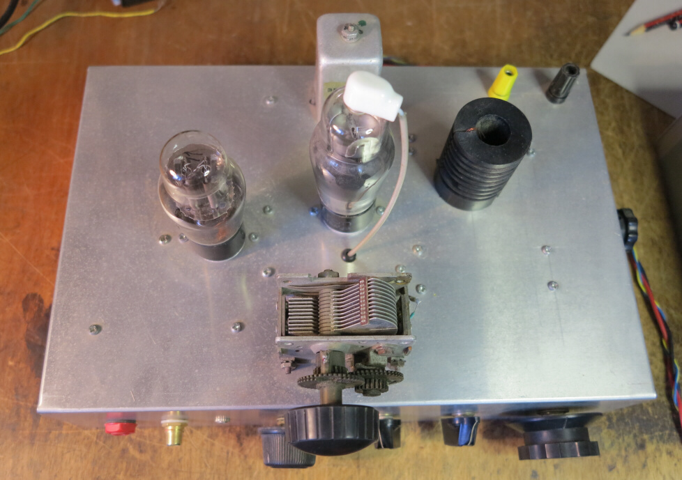
This section on regenerative receivers is based on my first receiver built in 1944 when I was 10.
Until about the mid forties in Australia most receivers in areas with no mains supply used
2 volt filament tubes - with the plate supply of 135 volts provided by three 45 volt batteries in series.
The filament current was normally 120 MA except for power output tubes. These had two filaments
in parallel to give a total current of 240MA.
Farmers usually arrived in town with a single cell 2 volt accumulator to be charged while they shopped.
The chargers employed Tungar rectifiers. These were thermionic diodes with a tungsten cathode and
filled with Argon to give a low voltage drop due to the cancellation of space charge by
positive Argon ions.
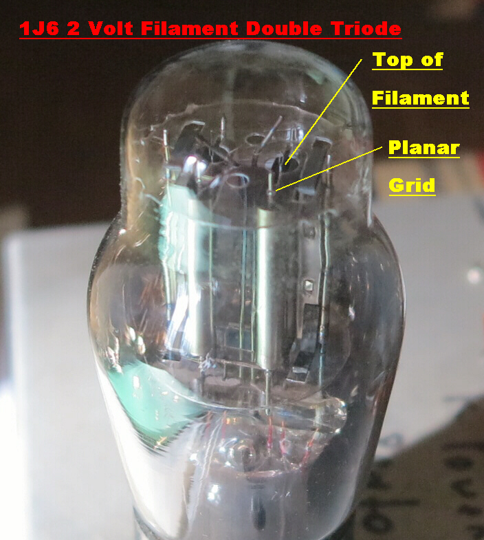 The filament of a 2 volt tube is V shaped with the apex of the V at the top of the tube.
The bottom of the V is tethered to two conductors connected to the A+ and A- rails.
The top of the V is supported by a thin spring loaded cantilever to tension the filament.
The shape of the filamentary cathode dictates that the grid and plate have
a planar geometry.
The filament of a 2 volt tube is V shaped with the apex of the V at the top of the tube.
The bottom of the V is tethered to two conductors connected to the A+ and A- rails.
The top of the V is supported by a thin spring loaded cantilever to tension the filament.
The shape of the filamentary cathode dictates that the grid and plate have
a planar geometry.
The grid support wires are therefore far apart and the grid must be wound with thick wire with wide
separation for structral integrity.
Since the position of the filament is not well determined, the grid cathode spacing is much larger than
that found in tubes with indirectly heated cathodes.
The above limitations produce a low mutual conductance (Gm) and a low amplification factor μ.
The negative end of the filament is normally earthed, so that the + 2 volts on
the positive end produces an increase in grid bias for electrons emitted from this
section of the cathode. To ensure
that the emission from all of the filament is utilised, the cutoff voltage for the tube must be
much greater than 2 volts. This implies a low amplification factor, so that the above
limitations in the geometry are acceptable.
The mutual conductance (Gm) for 2 volt filament tubes is of the order of 1MA/volt: modern tubes with
indirectly heated cathodes have a Gm ranging between 5 and 15MA/volt.
The maximum amplification factor (μ) for 2 volt filament tubes seldom exceeds 15: for tubes
with indirectly heated cathodes the amplification factor may reach 100.
For the 1K5 2 volt filament RF pentode at Vg = 0 volts:-
Gm = 1MA/volt
μ screen-grid = 15
For the 1J6 2 volt filament triode at Ip ≈ 3Ma:-
Gm = 1.25 MA/volt
μ = 15
The grid - cathode diode is an important element in the grid leak regenerative detector.
The voltage drop along the filament has a profound effect on the diode characteristics.
As the grid is driven positive, initially only electrons emitted from the negative end can
reach the grid, for the remainder of the filament is positive relative to the grid.
As the grid is driven positive more of the filament becomes active.
As the result, the plate conductance of the grid - filament diode is low and departs from the usual
three - halves power law.
This has a profound effect on the inbuilt automatic gain control of the regenerative detector.
The relative low bandwidth product of 2 volt filament tubes poses severe problems in the design of high gain superhetrodyne receivers, but is of little consequence in the regenerative receiver. Providing a gain of 1 can be achieved in the positive feedback loop at the carrier frequency, the required regeneration will occur. The regenerative detector was often followed by two stages of audio amplification. These were usually transformer coupled to give extra gain, usually about 10db.
1K5 2 Volt Filament Pentode :: Plate Characteristics
1K5 2 Volt Filament Pentode :: Mutual Characteristics
|
Plate Mutual Characteristic |
|
|
Plate - Screen Mutual Characteristic |
|
|
Transconductance |
|
The full circuit of the regenerative receiver is shown below:-
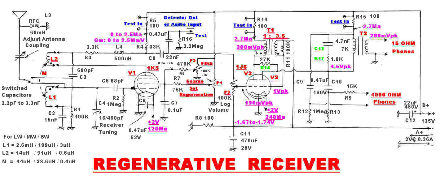
Three distinct actions occur within the 1K5 regenerative detector.
RF FEEDBACK
The mutual coupling M between L1 and L2 provides positive RF feedback.
The gain around this loop increases with frequency, so a second loop with complementary
characteristics is added in parallel. This second loop is provided by the capacitive divider
C2, C3.
The capacitive divider also bypasses the RF in the plate of the 1K5 and introduces a
single pole filter into the audio path. The resistive driving point impedance into the top
of the divider is determined by R3, R4. P3. This is 28.11K Ω : C2 and C3 in series give a
650.5pF capacitive load of 650.5pF - a time constant of 16.14 μSecs and a 3db turnover of
9.86KHz.
It is important that the onset of regeneration occurs in the middle of the plate current range
by choosing the correct value of the mutual inductance M.
For the inductors L1 and L2;-
M= k[L1xL2]1/2 where:-
k = coupling factor
L1 is the main tuning inductor
L2 is the feedback inductor in the plate
Now L2 is usually wound on top of L1 so k is more or less fixed, but the number of turns on L2
can be varied to adjust M.
The usual procedure in setting up the receiver is:-
[1] Tune the receiver towards the upper end of the band
[2] Set the plate current of the detector at the value required for the onset of regeneration.
[3] Change the number of turns on L2 until regeneration just starts.
[4] Tune the receiver to the lower end of the band.
[5] Adjust C2 and possibly C3 for regeneration.
Note: This receiver has two positive feedback paths to give more even regeneration across
the band.
TWO POSITIVE RF FEEDBACK PATHS
It is highly desirable that little variation in the operating point for the 1K5
occurs when the receiver is tuned across the broadcast band from 500KHz to 1600KHz.
This implies that the transfer impedance around the feedback loops should remain fairly
constant with frequency.
It will be shown that the modulus of the transfer impedance |ZT| of the loop via the mutual
inductance varies roughly as ω2 , so the variation across the band would be
about (1600/500)2 = 10.2 - highly undesirable.
A second parallel capacitively coupled feedback loop is introduced.
The modulus of the transfer impedance of this loop tends to fall off at high frequencies, so the two add
to flatten the variation with frequency.
THE MUTUAL INDUCTANCE LOOP
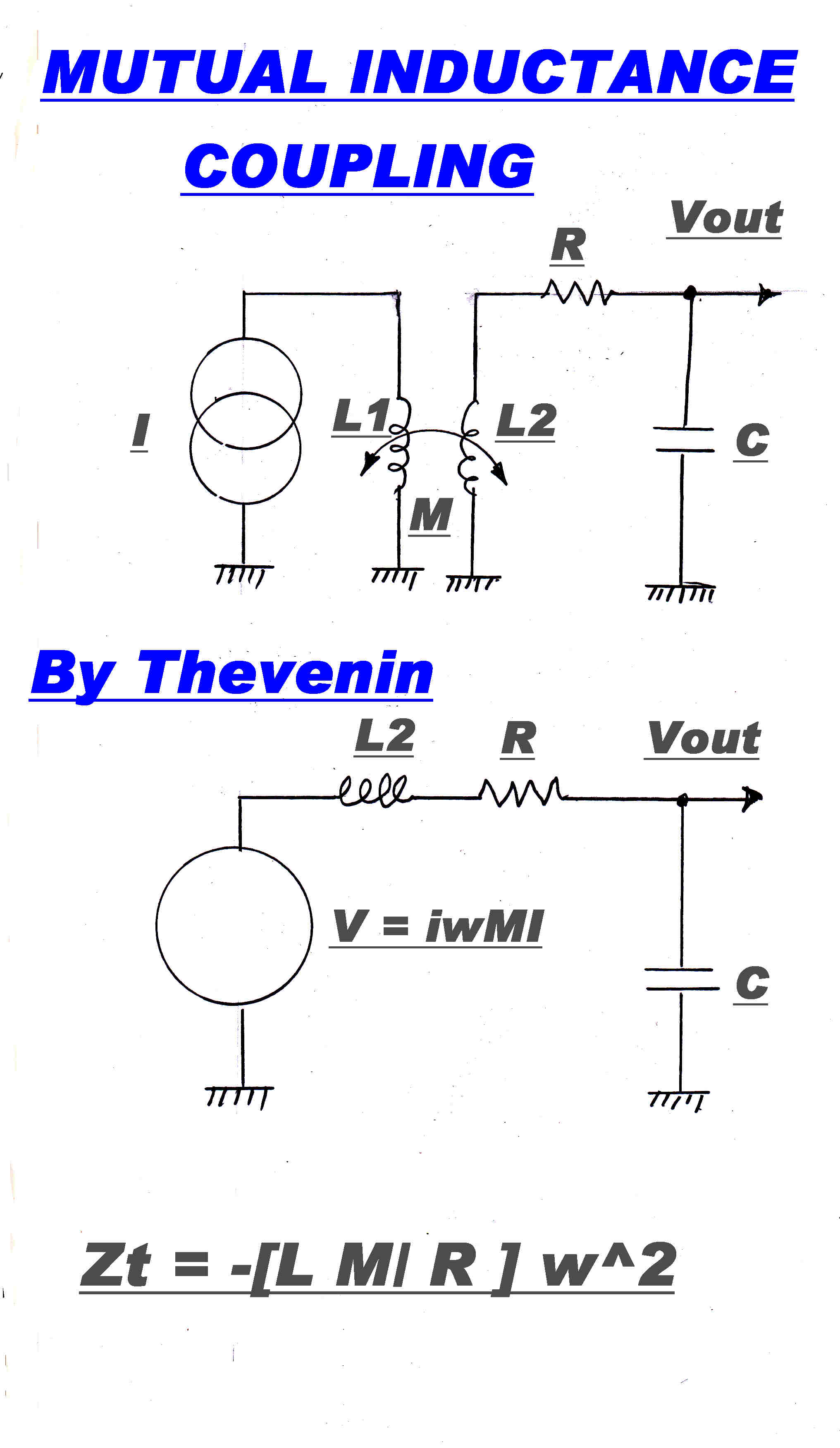 An approximate equivalent circuit for the mutually coupled positive feedback loop is
shown opposite.
An approximate equivalent circuit for the mutually coupled positive feedback loop is
shown opposite.
More accurate transfer impedance analyses throw up high order polynomials which are difficult to interpret.
An application of Thevenin produces a single loop system.
Note that at resonance XL2 = - XC, so they vanish from the circuit.
The approximate transfer impedance ZT [ Vout/Iin ] is given by:-
ZT(i ω) = - [ L2 M/R ] ω2
As pointed out above, this woud produce a gain variation of 10.2 over the broadcast band.
R - the series resistance of the tuning inductor - increases with frequency and tends to reduce the variation.
R is produced mostly by skin effect and proximity effect from turn to turn and varies in a complicated manner
with frequency.
An inductor wound with Litz wire behaves differently from one wound with solid copper wire.
THE CAPACITIVE COUPLED LOOP
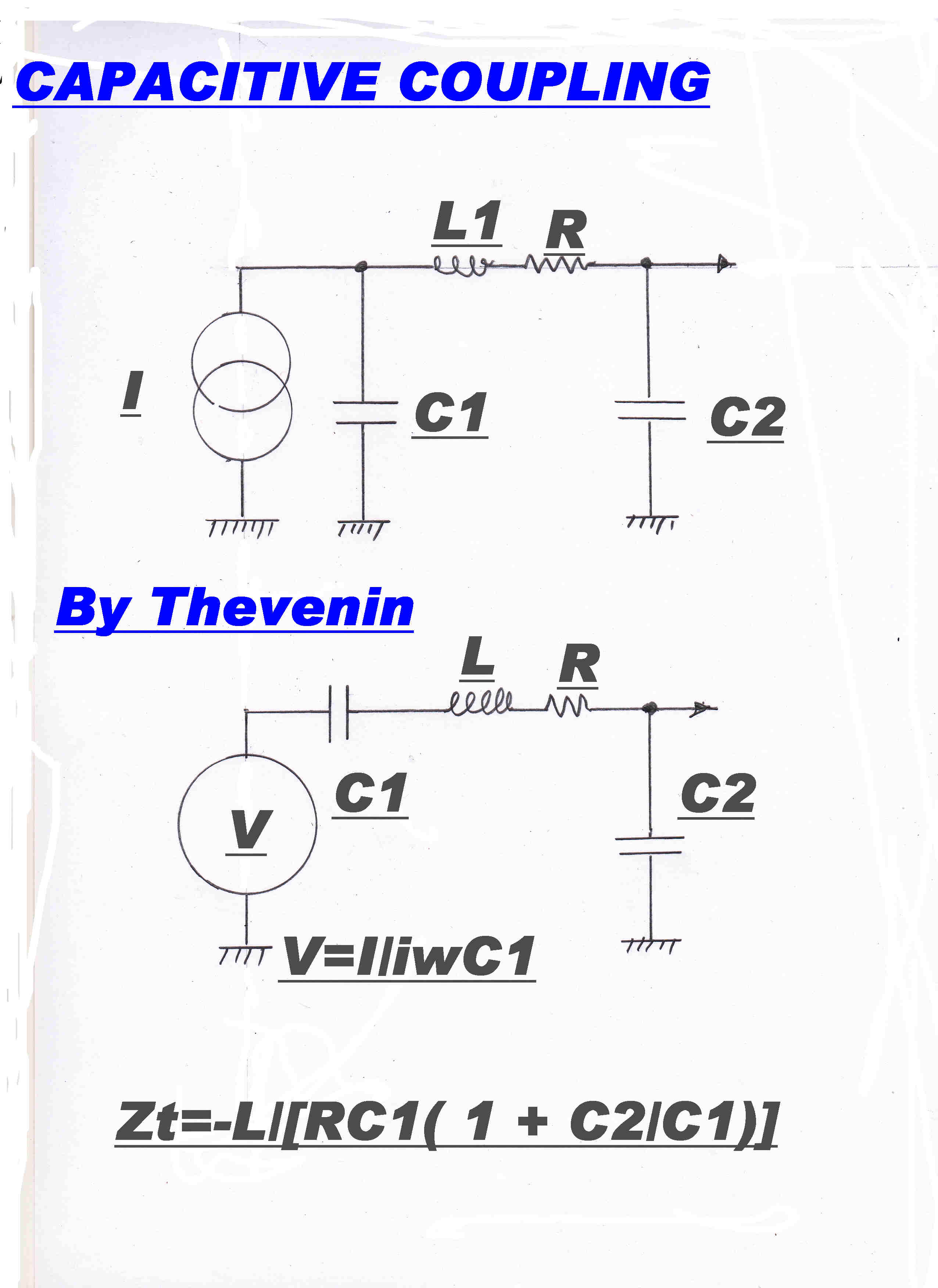 An approximate equivalent circuit for the capacitively coupled positive feedback loop is
shown opposite.
An approximate equivalent circuit for the capacitively coupled positive feedback loop is
shown opposite.
More accurate transfer impedance analyses throw up high order polynomials which are difficult to interpret.
An application of Thevenin produces a single loop system.
Note that at resonance XL = - XC, so they vanish from the circuit.
The approximate transfer impedance ZT [ Vout/Iin ] is given by:-
ZT(i ω) = - [ L/RCC1 ( 1 + C2/C1 ) ]
Now C2 is the tuning inductor and C1 must be made much larger than C2
if it is not to reduce the frequency range tuned by C2.
ZT then remains essentially constant across the band.
But R increases with frequency and the transfer impedance will decrease with frequency, and so provide some
compensation for the increase in the mutually coupled loop.
THE COMBINED LOOPS
The circuit of the combined loops is shown below.
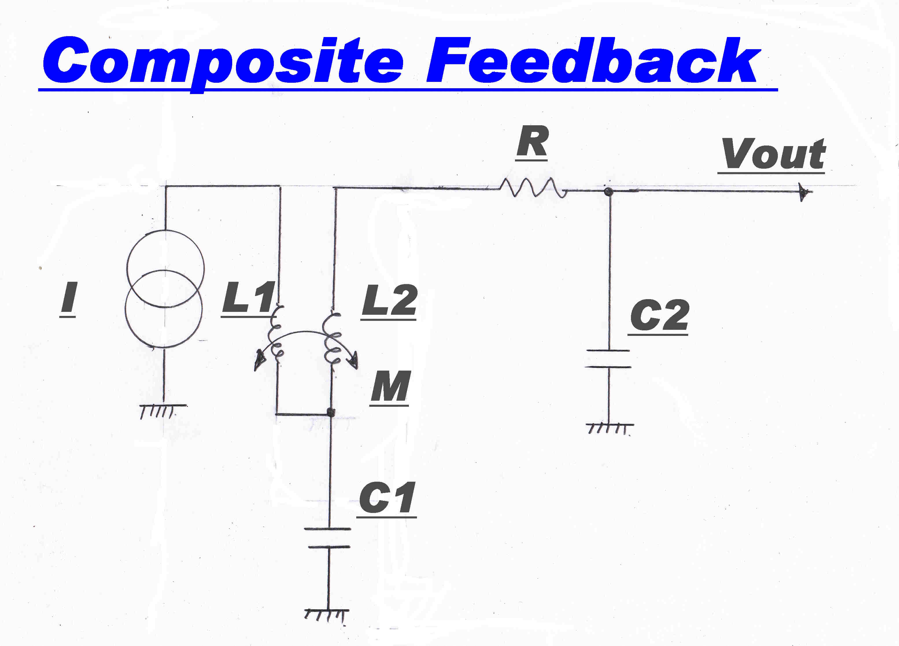
GAIN CONTROL
The overall gain, A, of the RF amplifier is well described by the
simple feedback equation:- A = α/( 1 - α β )
Here α is the forward gain in the 1K5 pentode and β is the transmission around the
positive feedback loop.
The aim in the regenerative detector is to make the product (α β) approach 1 so
that the denominator ( 1 - α β ) becomes very small to give a very large value for A.
Here the feedback β is fixed by a passive network with fixed components. Regeneration is
controlled by a variation in the gain ( α ) of the 1K5 pentode. Variation of 1K5 screen voltage
changes the Gm of the tube. The forward gain α is directly proportional to Gm.
Note:- The grid of the 1K5 must remain at 0 volts since the grid - cathode diode is used
as a detector. The grid develops a very small negative bias. Electrons are emitted from
the cathode with a Maxwellian velocity distribution. Some of high energy are intercepted
by the grid. The resultant current through the 1M Ω grid leak resistor R2 develops a small
negative voltage. In the 1K5 this is about -120 millivolts.
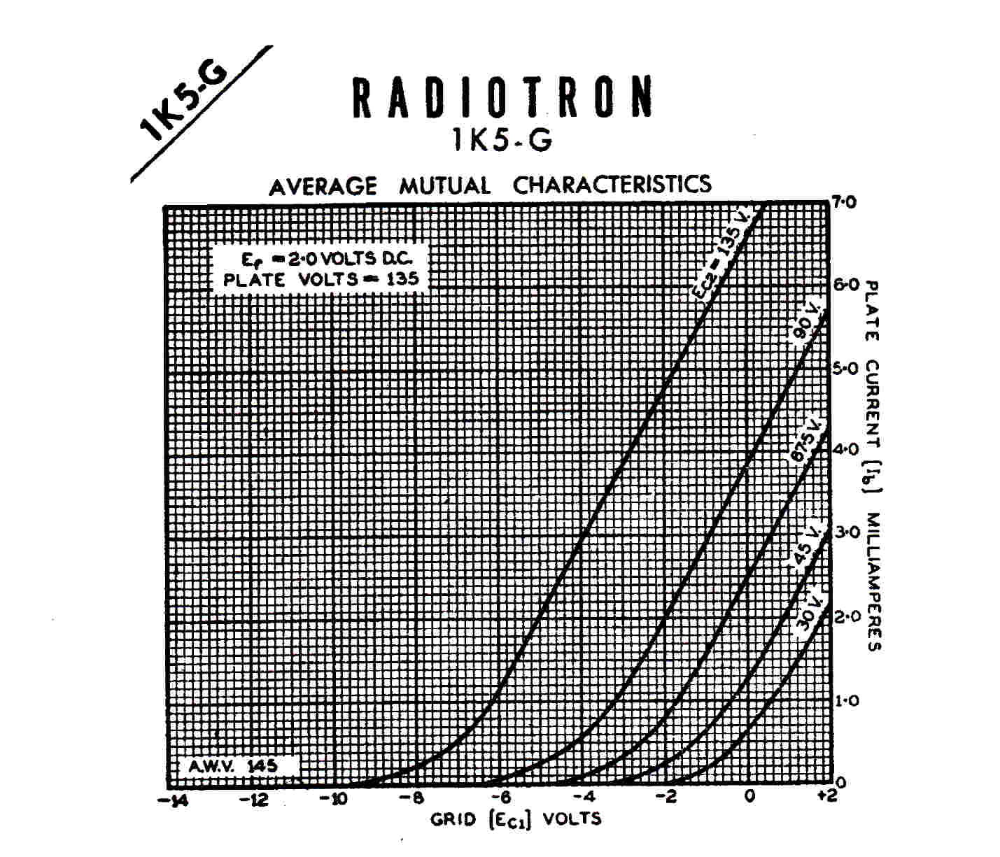
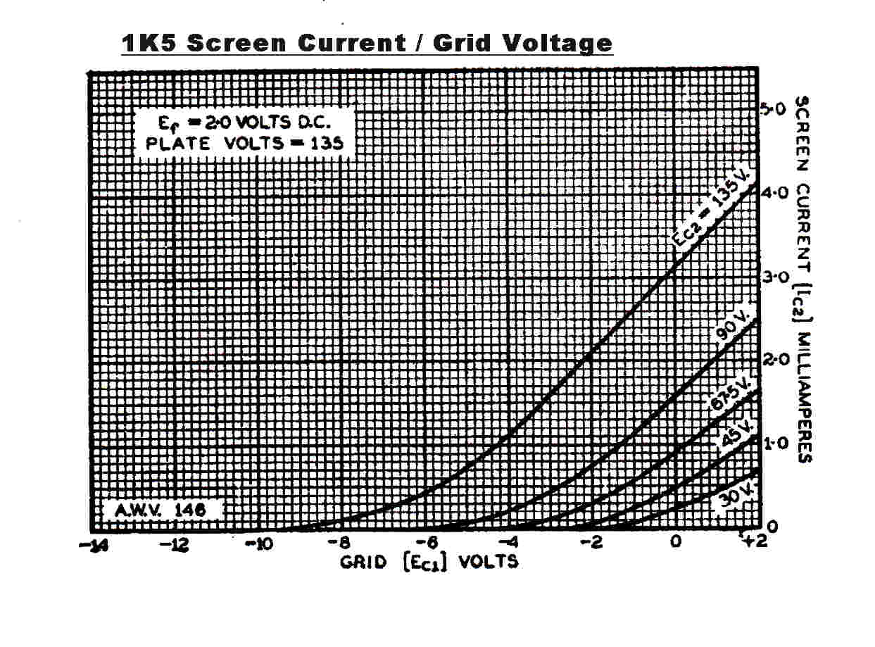
The variation of Gm with screen voltage is shown in GRAPH4
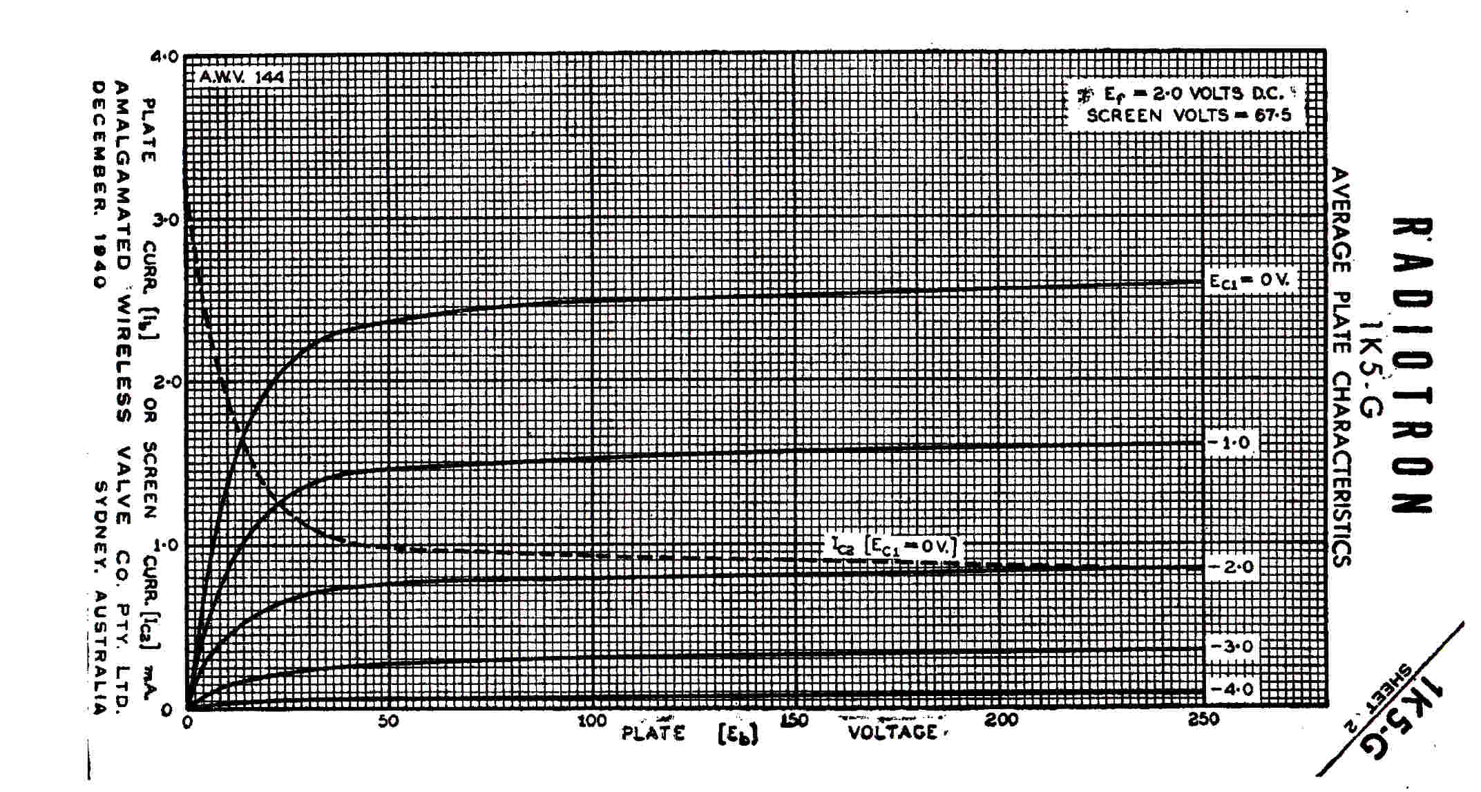
The mamaximum permissible screen voltage is 67.5 volts, so, with 0 volts on the
grid, 67.5 volts on the screen, and a plate voltage above the knee:
Iplate = 2.5MA ( GRAPH1 OR GRAPH2 )
Iscreen = 0.9MA ( GRAPH3 )
Gm = 1.03 MA/volt ( GRAPH4 )
The screen voltage, and hence regeneration, is set by the coarse potentiometer P1
and the fine potentiometer P2. The maximum screen voltage is given by:-
Vsmax = VB - IsxRs = 135 - (0.9x10-3)x(75x103) = 67.5
The plate load of the 1K5 is chosen to keep the minimum plate voltage just above
the knee of the plate voltage curve (GRAPH1)---
Vpmin = 135 - (2.5x10⁻³)x( 33x103 ) = 52.5
 The RF voltage developed across the tuning capacitor C4 is applied
to the grid - cathode diode of the 1K5 via the grid leak capacitor C5.
The RF voltage developed across the tuning capacitor C4 is applied
to the grid - cathode diode of the 1K5 via the grid leak capacitor C5.
A negative DC voltage develops across the capacitor, so that the diode conducts
only on positive peaks.
This negative offset is the demodulated audio signal.
During the remainder of the RF cycle the capacitor discharges through the grid leak resistor R2.
The average rate of discharge must be higher than the maximum rate of change of the modulation
envelope so that the detector does not "hang up". This sets an upper limit on the time constant
R2C5.
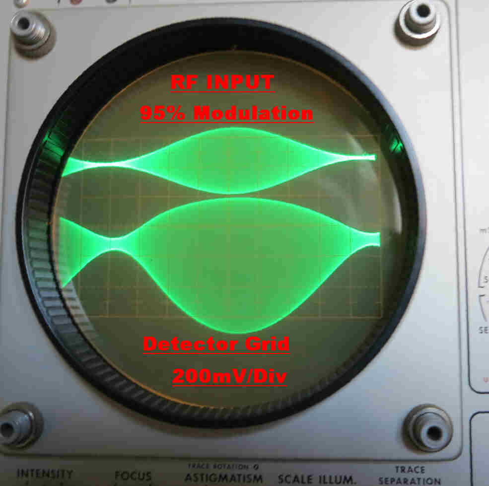
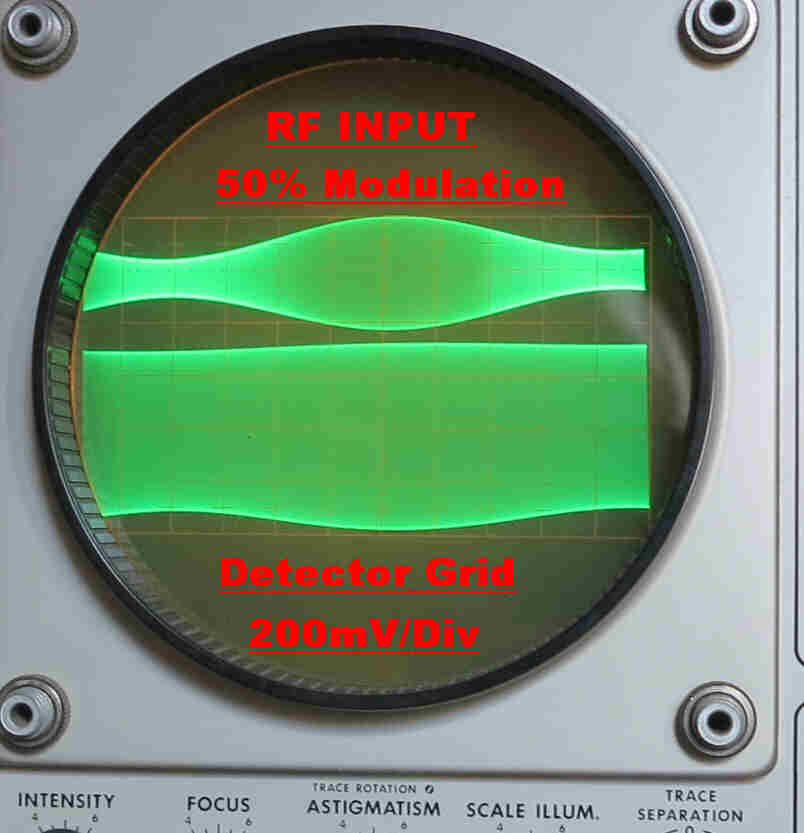
The oscillogram shows the voltage on the 1K5. grid.
NOTE:-
(a) The positive peaks extend up to about 200mV.This is a result of the low plate conductance
of the grid - cathode diode.
(b) The grid potential at minimum carrier is about -120 mV. This bias is due to the
interception of high energy electrons as described above.
Audio Amplification in The Regenerative Detector
 Analytic treatment of the audio amplification in the detector is almost impossible,
for the audio signal is mixed with a high level modulated carrier.
Analytic treatment of the audio amplification in the detector is almost impossible,
for the audio signal is mixed with a high level modulated carrier.
It is appropriate to treat the detection and audio amplification as a total system and
investigate their combined effect on distortion experimentally.
The audio gain can be roughly estimated as follows:-
Assume Vg = 0 then :-
Ip = 2.5Ma
Gm ≈ 1MA/volt
Resistive load Rl = ( R4//P3 ) = 33k//100k = 24.8k
A = GmxRl ≈ 25
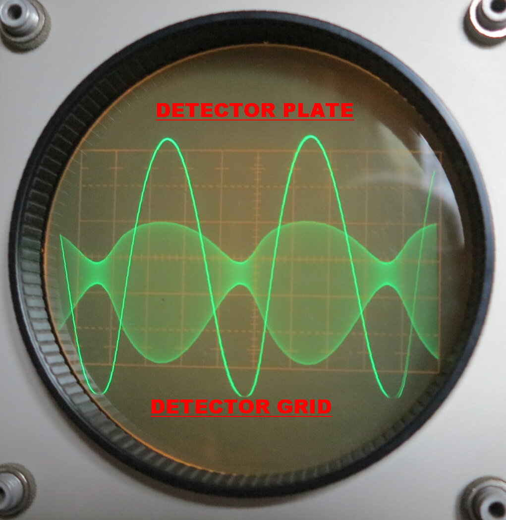
The audio signal on the plate of the regenerative detector is shown. Note that it is
remarkably free from distortion. In the usual superhet. receiver using a diode detector,
distortion frequently occurs at this modulation level, since the AC load on the detector
is lower than the DC load. In some cheaper receivers the diode detector also provides the
AGC control voltage. The voltage on the capacitors of the AGC filter bias the diode and cause
further distortion at high modulation levels.
These effects are not present in the grid leak detector and the receiver, for all its simplicity,
can sound remarkably clean.
The details of the audio amplifier can be seen in the
receiver circuit
It consists of two transformer coupled triodes.
Transformer coupling was attractive for two reasons:-
[1] The transformer ratio was usually 1:3.5 thus increasing the gain by 10db.
[2] With a filamentary cathode it is impossible to stabilise the operating point of the
tube with cathode bias. Upward drift of the plate current can cause "bottoming" with
a resistive load. This cannot happen when the load is the primary of a transformer with
a low DC resistance.
The transformer used in the receiver was the "Pep-Punch" unit from the original 1944 receiver.
It dates from the late twenties.
The response of the amplifier is largely determined by the transformer and is shown below:-
|
|
|
The response of the transformer varies with the driving impedance.
Low Frequency Response
The 3db low frequency turnover, fL, is given by: fL = (Rp + Rd)/2ΠLp
where Lp = primary inductance: Rp = primary resistance: Rd = driving resistance.
If Rd = 0 the low frequency cutoff is 15Hz. If Rd = 10k ( typical plate resistance of a triode )
then the low frequency cutoff is 488 Hz. This demonstrates that receivers using the "Pep-Punch"
audio coupling transformer would suffer from a very poor bass response.
Further, the nonlinear magnetisation curve for the iron core produced distortion at low frequencies.
An air gap was usually introduced into the magnetic circuit to optimise the primary inductance
in the presence of DC plate current. This reduced the distortion.
High Frequency Response
The resistance of the primary and secondary, the leakage reactance and the self capacity of
the windings form a series resonant circuit. This produces a peak of 11.4db at 11.9KHz.
When the driving impedance is increased to 10KΩ, the Q of the tuned circuit decreases and the
peak in the response disappears to produce a -3db frequency of 8KHz.
It is believed that the dip at 55KHz and the secondary peak at 82KHz is produced by inter-winding
capacity.
Addition of Negative Feedback
Since modern high fidelity phones were to be used with the receiver, it was decided to apply
negative feedback over the coupling transformer and output stage to improve the response and
lower the distortion.
High gain amplifiers with filamentry cathodes tend to be microphonic, so the lower gain under
feedback reduced this undesirable effect.
The circuit elements added for audio feed back are marked in green in the
receiver circuit.
Feedback is applied from the output plate of V3 to the primary of the coupling transformer
T1 via R18 (27K). It therefore covers the coupling transformer - the output triode V3 and
the primary of the output transformer T2.
If the gain around this loop is A and ΔV is the change in voltage on plate 2, then
( 1 + A ) ΔV appears across the feedback resistor R18. This shunts the load in
the plate of V2 with a resistance of R18/( 1 + A) :: 27k/( 1 + 15) = 1.69K. This increases
the plate current swing - and hence the distortion - in the driver V2. Since the level is low this
is of little consequence.
The gain of the first stage is only 1.58, so Miller effect increases the grid plate capacity
by 2.58, and so does not reduce the high frequency response when the output resistance from
the volume setting potentiometer is at a maximum. The maximum output resistance from the
potentiometer is 33.25KΩ.
C13 - R17 provide a shelf in the high frequency response to increase the gain margin and the
stability of the feedback loop.
With a peak voltage of 200mV across the 15 Ω phones ( loud signal) the measured distortion
for the 1J6 amplifier at 2KHz is:-
Second Harmonic: 0.4%
Third harmonic: 0.08%
Fourth Harmonic: Not measurable
Fifth Harmonic: 0.53%
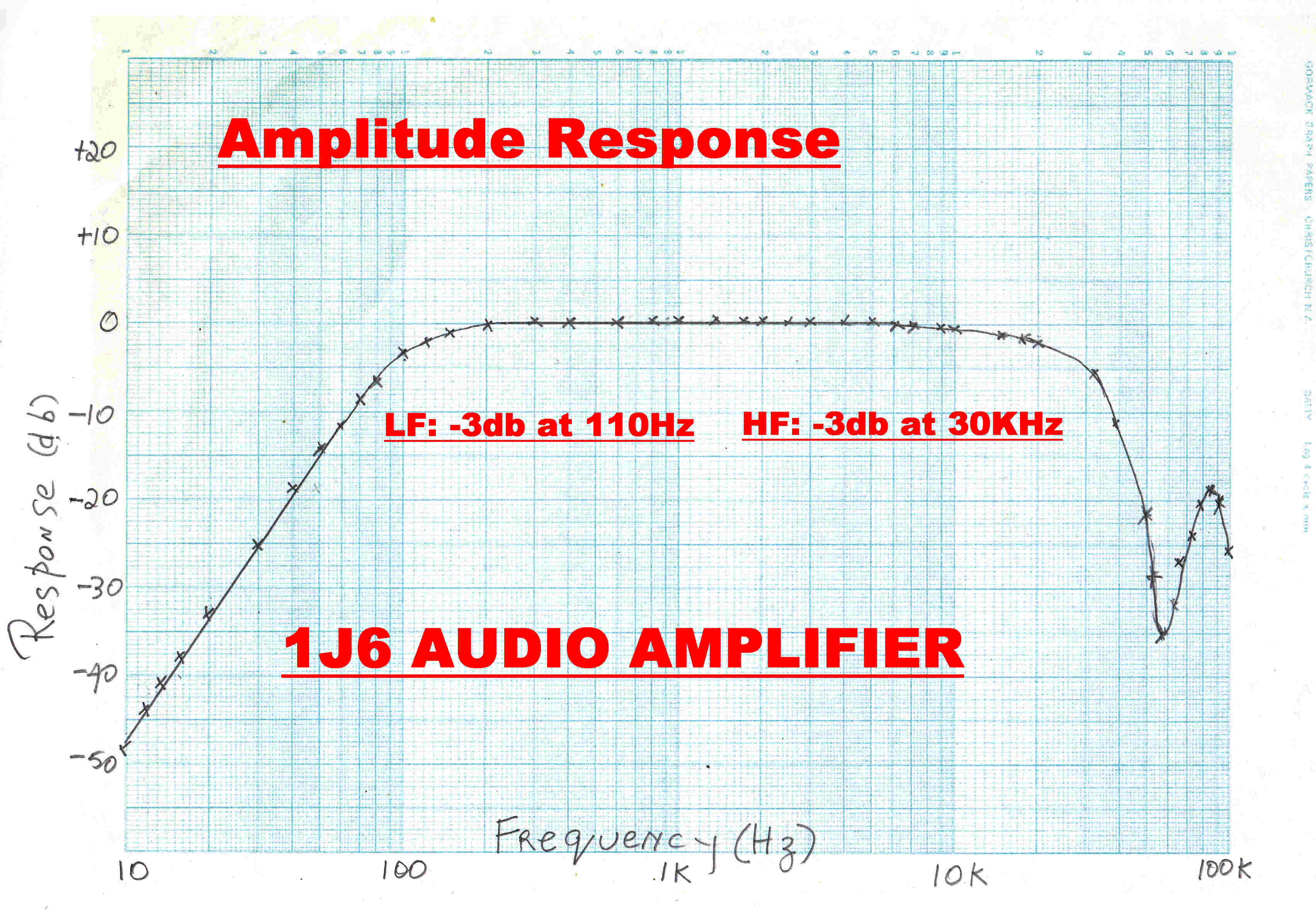 The overall frequency response of the 1J6 amplifier is shown opposite.
The feedback has extended the combined low frequency response of both transformers down to 110Hz
and extended the high frequency response up to 30KHz. as well as reducing the distortion.
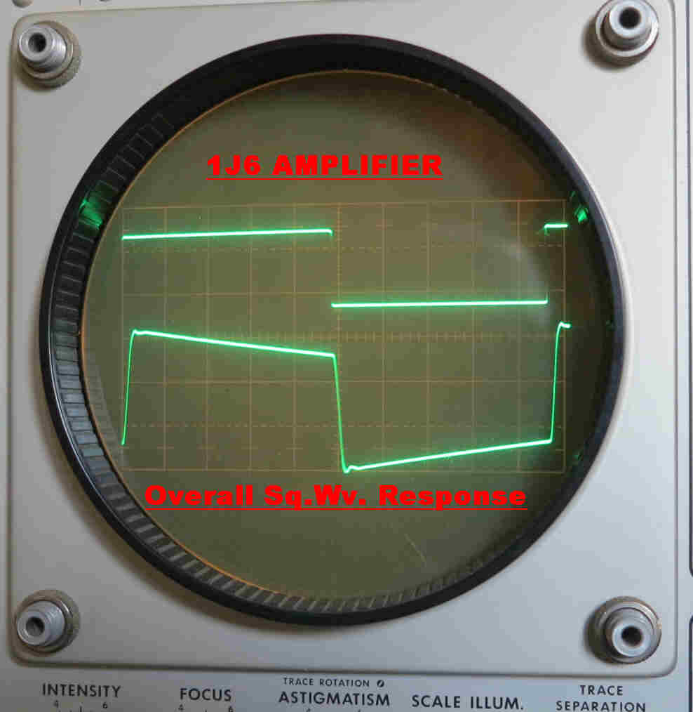 The overall square wave response corresponding to the above steady state response is
shown opposite.
The overall square wave response corresponding to the above steady state response is
shown opposite.
Freedom from overshoot and excessive ringing is due to the gentle turnover in the high
frequency response about 30KHz.
The droop on the top of the square wave is due to the high value of the low frequency
turnover at 110Hz.
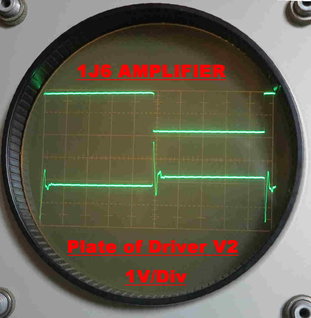
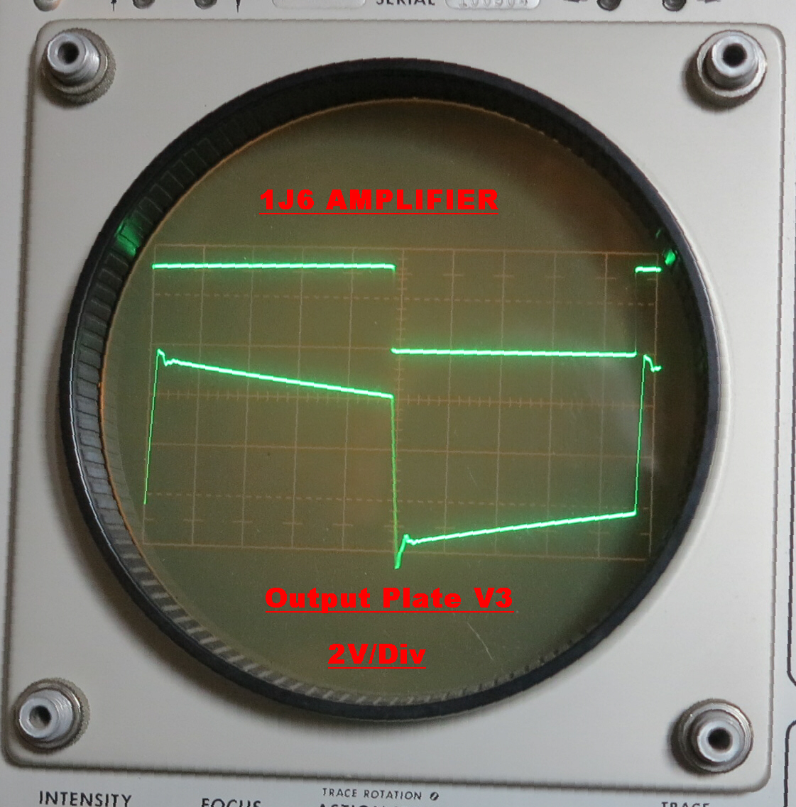
The voltage waveform at key points in the 1J6 amplifier is shown below:-
|

|
|
|
Within feedback loops large transients occur to force the required response.
The initial spike is generated to overcome the poor transient response of
the audio coupling transformer. |
The very large spike on the primary of the transformer results in a much
smaller spike on the secondary. This increases the rate of change across
the capacity of the primary of the output transformer and the shelf network
R17,C13 and thus lowers the overall rise time. |
The capacity of the output transformer primary and the shelf network R17,C13
has absorbed the
spike on the grid to give a fast rise time with a small overshoot.
This overshoot is suppressed by the leakage reactance of the output
transformer to give close to an overall monotonic response.(see above) |
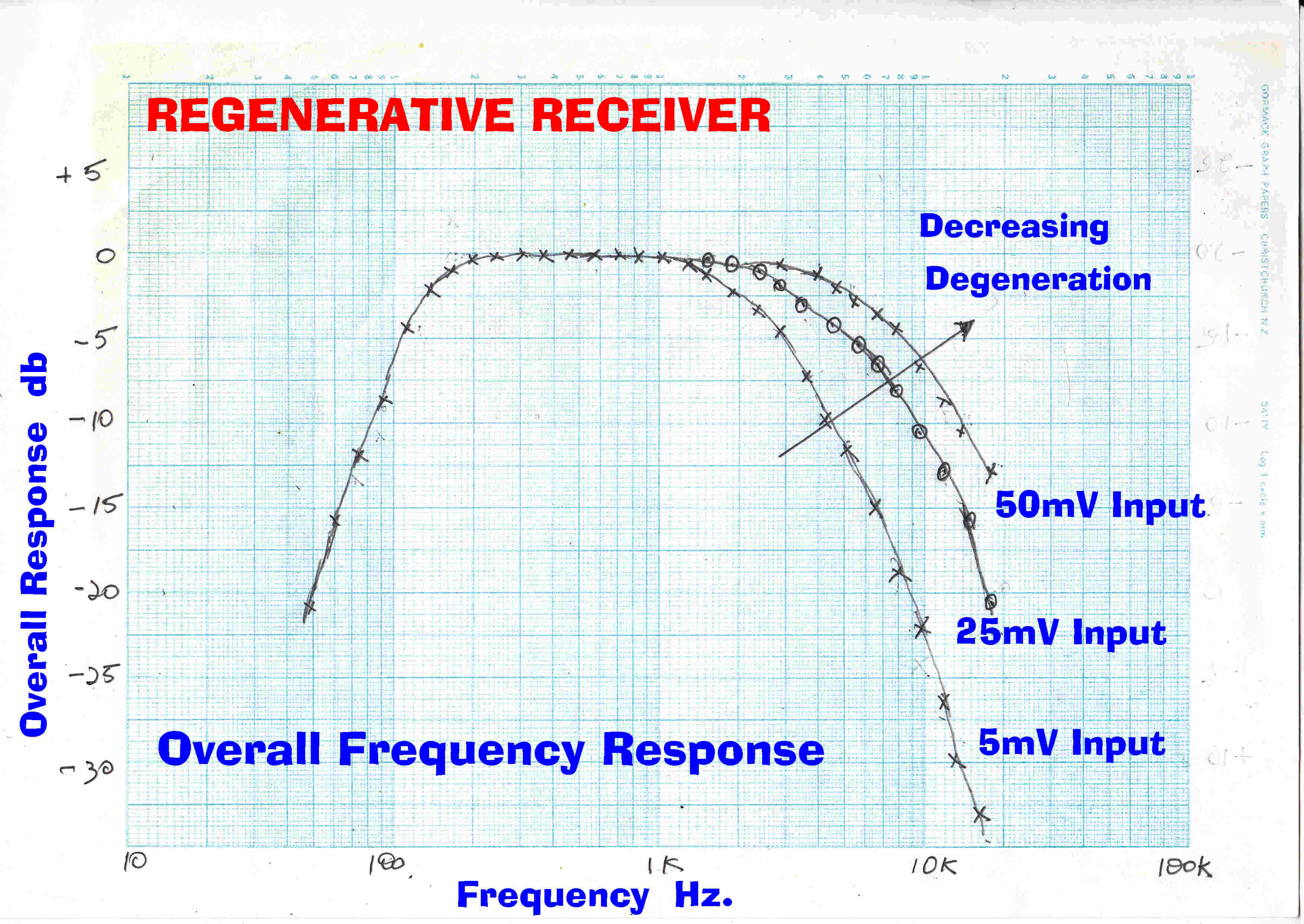 The bandwidth of the regenerative detector decreases as the gain is increased with
regeneration.
The bandwidth of the regenerative detector decreases as the gain is increased with
regeneration.
With no regeneration the receiver bandwidth is determined by the loaded Q of the tuned circuit
in the grid.
The total bandwidth between 3db points is given by:-
Btot = fc/Q : and the modulation bandwidth is fc/2Q.
The ultimate slope is always 6db/octave: only the turnover frequency changes.
In the graph shown opposite the regeneration is decreased to keep the audio output constant
while increasing the carrier input level.
The signal level on the detector grid must be limited to prevent distortion.
Adjustment of the antenna coupling capacitor together with the reaction control will
usually give a satisfsctory level with the required bandwidth.
In vacuum tubes space charge control determines plate current over the usual range
leading to the three halves power law: Ip = (Vp)3/2
At low currents an etirely different mechanism arises very similar to that found in a
bipolar transistor - control by an energy barrier. In fact the tubes closely resemble a transistor
operated at the temperature of the tube cathode.
The large negative grid bias acts as an energy barrier and allows only those electrons
at the high end of the Maxwellian distribution through. This has two effects:-
[1] The Ip/Vg transfer characteristic now becomes exponential
[2] The Gm/Ip ( an important parameter in amplifier design) improves over that found
with the three halves power law.
In DC coupled slow speed amplifiers tubes were usually operated with very low
plate currents for this reason.
As described above, the grid automatically adopts a bias in this region due to intercepted high
energy electrons and so, for low signal levels, the grid-cathode diode exhibits
an exponential law. This results in distortion.
The plate current is determined by space charge limiting and so exhibits a three halves power law.
This can be expanded in a Taylor series with the even order terms resulting in a low frequency
component - in other words, they produce detection. This is also accompanied by distortion.
It is easy to show that the second order term introduces second harmonic distortion
of m/4, where m is the modulation percentage.
The above non-linear processes exist together in the regenerative detector and make exact
analysis difficult.
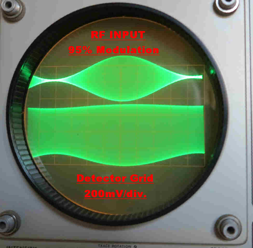
Very large values of regeneration compress the modulation on the carrier appearing on the grid of the regenerative detector.
The effect is illustrated in the oscillograms shown below:-
|
|
|
|
|
In this oscillogram a moderate amount of regeneration is used. This corresponds to the condition for "normal" listening to a local broadcast station. There is evidence of a small amount of modulation compression. |
In this oscillogram the amount of regeneration is increased. |
In this oscillogram the regeneration is increased still further. |
The following explanation is suggested for the compression mechanism:-
[1] With large amounts of regeneration, very small changes in the forward gain α
produce large changes in the overall gain A .
This is readily seen from the equation A = α/( 1 - α β ) where
αβ ≈ 1
[2] With an increase in RF amplitude during a positive modulation cycle, the average
grid voltage goes negative - reducing the Gm of the tube - and hence the forward gain
α.
This, in turn, produces a large reduction in overall gain A.
[3] As the carrier amplitude increases, so the forward gain A decreases.
That is, we have compression.
The above mechanism also operates for slow changes in carrier level, and so provides
a rudimentary form of automatic gain control - AGC.
This "inbuilt" AGC probably explains why the regenerative receiver produces good
short wave reception.
Tuning a regenerative receiver for best results requires a knowledge of the
internal topology.
There are five controls:-
(1) Tuning Capacitor:
This sets the frequency.
(2) Band Switch :
This sets the frequency band: Long Wave: Medium Wave: Short Wave
(3) Regeneration Control: Coarse and Fine:
This sets the RF gain of the detector.
Beyond a certain point the detector will burst into oscillation and
beats with the incoming carrier to produce a loud beat note.
The oscillation is radiated by the antenna and interferes with other
receivers in the locality so should be avoided.
(4) Antenna Coupling:
This controls the level of RF injected into the detector from the antenna.
There is an optimum value for minimum distortion.
The coupling depends on the type of antenna.
(5) Volume Control:
This determines the level of detector output into the audio amplifier
Minimising The Distortion:
It has been pointed out above that two separate mechanisms for detection exist:-
(1) Diode detection by the grid - cathode diode.
(2) "Anode Bend" detection due to even order curvature in the grid - plate
transfer characteristic.
Distortion decreases with signal amplitude in the first and increases with
signal amplitude in the second.
There is therefore an optimum signal level for minimum distortion
Advancing the reaction cuntrol to give more positive feedback increases
the signal level but decreases the bandwidth.
The reaction can be backed off to increase the bandwidth and the
signal level increased with the antenna coupling to give low distortion.
This is an example of the audio quality achievable with a simple
regenerative receiver.
The antenna was a length of hookup wire thrown out the back door
over a hibiscus bush: again illustrating the robust nature of AM tansmission
The signal was taken across the low impedance phone jack for high
fidelity headphones.
Play Example 1
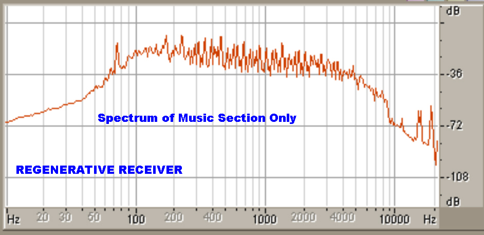
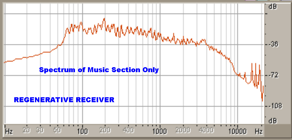
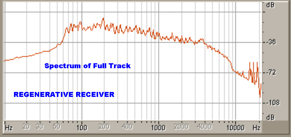
The spectrum of the audio signal is given below:-
|
|
|
The 9KHz sharp cutoff filter at the transmitter is evident. |
Since this spectrum contains about 50% speech the low frequency amplitude
has fallen off. |
This is an example of the audio when tuning a regenerative receiver
The track starts when tuning into a commercial station 4KQ [690 KHz] with
the heterodyne whistle at the beginning.
The receiver is then tuned to 4QR [612 KHz]
Play Example 2
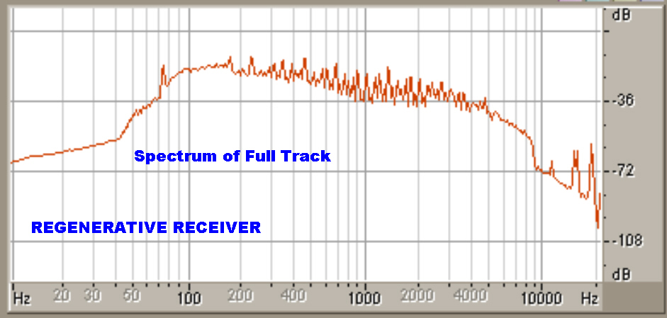
The spectrum of the audio signal is given below:-
|
|
|
The 9KHz cutoff filter does not appear to be as sharp in this transmitter |
Since this spectrum contains about 50% speech, the peaks have
been somewhat ironed out. |
The circuit of a regulator to supply filament voltage to 2 and 1.4 volt filament
receivers is shown below.
Special precautions are taken to prevent overvoltage to prevent damage to the tube filaments.

Circuit Description
Q1 and Q2 form a bistable in which the transistors are either off or saturated.
The turn on transient through the 22uF capacitor triggers the bipolar into the "on" state
and HT is applied to the regulator via the diode D3.
Note: Red Leds make excellent 2 volt Zener diodes and this property is used throughout
the regulator.
If the output voltage exceeds about 2.7 volts, Q5 is turned on and triggers the bistable off,
thus cutting the HT to the regulator.
Q7 and Q8 provide a constant current drive.
The collector current from Q8 pulls the 22uF integrator capacitor on the base of Q10 positive.
When the output rail reaches 2.0 volts, Q9 turns on and provides integrator
action around the feedback loop to give a very low DC error.
A high frequency loop for fast regulation occurs around the loop Q10,Q11 and
the pass tansistor Q13. The stabilising pole of this loop is provided by the 4700uF output
capacitor and the output resistance of Q13.
The 47 ohm load on the 1.4 volt output ensures that the 2200uF capacitor does not
charge up past 1.4 volts due to leakage currents in the diodes D11 and D12 when the
this output is open circuited. It also provides a working load on the regulator
when there is no external load.
When the output current through the pass transistor Q13 exceeds 1 amp, Q12 turns on and
bypasses the base drive current to Q13, and so limits the output current.
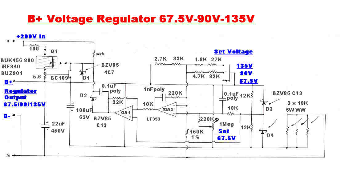
The B+ regulator is designed to produce the three standard high tension voltages
used in battery receivers --- 67.5, 90, and 135volts.
The three 10K resistors provide energising current for the two 13 volt Zener diodes to give +(-)
13 volt rails for the Op-Amps.The positive rail is also used as a reference.
The condition for equilibrium in the regulator dictates that the negative and positive
inputs of the OpAmp OA2 be at the same potential.
If:-
Rt is the top of the divider between the negative terminal of OA2 and the positive rail.
Rb is the bottom resistor to earth.
Vr is the reference or rail voltage (13V)
Vout is the required regulated output voltage, then:-
Vr/Rt = (Vout - Vr)/Rb or:-
Rt = Rb/( Vout/Vr - 1 )
Rb is made 150K and this gives the following values for the top resistor Rt:
Vout = 67.5volts: Rt = 35.78K
Vout = 90 volts: Rt = 25.32K
Vout = 135 volts: Rt = 15.98K
Provision is made to trim the 67.5 voltage output since it is the most critical.
The integrator provided by the 1nF feedback capacitor in the feedback loop around OA2
ensures no long term error in the regulated output. There is also a fast path through the
OpAmps to handle transients. The stabilising pole of this loop is formed by the
the ouput impedance of the pass transistor Q1 and the 22uF capacitor.
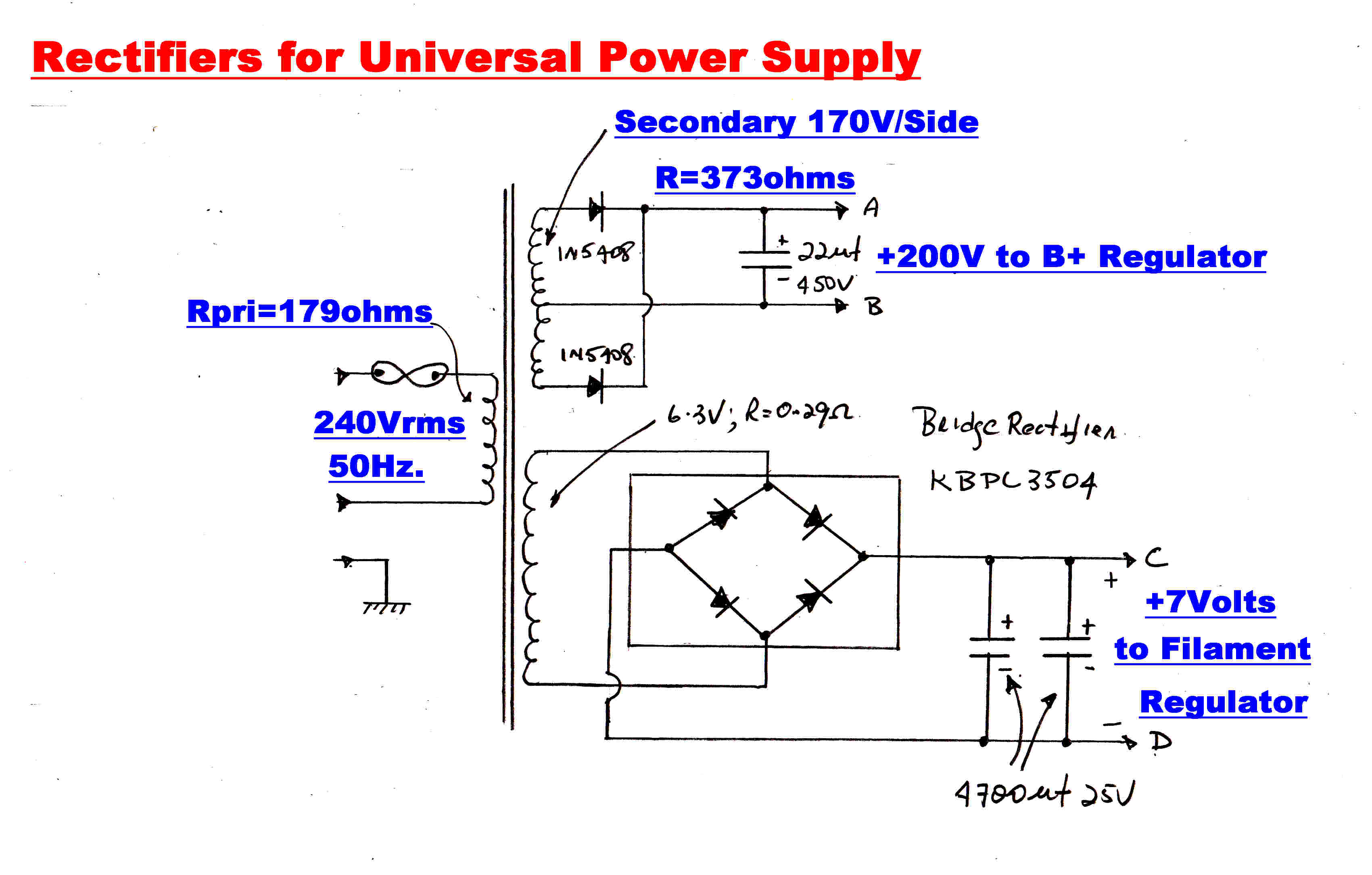
The rectifiers are stock standard and are included for the sake of completeness.