4QG - 4QR BRISBANE -- A SHORT TECHNICAL HISTORY


CONTACT : COMMENTS AND QUESTIONS
back/home
This is an attempt to give a short technical account of broadcast antenna,
transmitter and vacuum tube development from about 1925 to 1980.
The 4QG and 4QR transmitters of the National Broadcasting Service here in
Brisbane serve to illustrate the evolving techniques.
Transmitter performance was partly dictated by receiver design.
There was little point in designing transmitters several orders of magnitude better
than the receivers.
An exception to this was the WLW Rockwell transmitter.
Since it reflects on transmitter performance, receiver design is discussed.
Particular attention is paid to the Breville 239 designed in Australia in 1940
and, by far, the best domestic broadcast receiver I have encountered.
In Brisbane the national program was broadcast by two transmitters - 4QG and 4QR.
4QG was established by the Queensland Government in 1925.
It opened on Monday 27 July 1925 with a 500 watt transmitter, most probably
on 385 metres - 780KHz.
Transmission with the 5KW transmitter started at 3pm Thursday 22 April 1926.
Note that the powers quoted are DC input powers to the final stage of the transmitter.
The radiated carrier power would have been considerably less.
Both the studios and transmitter were situated in the Treasury Building
in George street Brisbane.
4QR started transmission on Friday 7th June 1938 with a 5KW transmitter situated
at the Central Telephone Exchange Elizabeth street opposite the Catholic Cathedral.
The radiator was a self supporting tower on the roof.
Both transmitters were near General MacArthur's headquarters and were considered a threat
should they act as a homing beacon.
Both transmitters were moved to Bald Hills - a swampy area North of Brisbane.
Transmission from a 650 foot shared monopole started on 1st September 1948.
4QR - a 10KW transmitter modulated at low level - on 590KHz broadcast the "SECOND" program
of the ABC - talks and classical music.
The input to the modulator passed through a filter with a sharp cutoff at 10 KHz and a peak limiter.
There was no compressor amplifier.
4QG - a 10KW transmitter plate modulated at high level - on 790KHz broadcast the "FIRST" program
of the ABC - hit parades, comedy, sport etc.
The input to the modulator passed through a filter with a sharp cutoff at 10 KHz, a peak limiter
and a compressor amplifier.
A mono FM service was started on 6th October 1953 from a transmitter situated at Mirrimbul
on Mt.Cootha with a power of 1KW on a frequency of 91.1 MHz.
The peak deviation was +(-)75KHz and the transmitter shared programs with the 4QR transmitter
via landlines equalised to 15KHz.
The transmitter used Armstrong's original method of FM modulation -- phase modulation
followed by 12 frequency multipliers.
In 1956 I was in a position to encourage electrical engineering students to design and build
low distortion high bandwidth AM and FM tuners.
The 4QR signal exhibited audible distortion - an intolerable state of affairs.
The distortion was traced to the misuse of feedback and the transmitter was redesigned by PMG
engineers who applied heavy envelope feedback to the transmitter.
After the redesign the AM and FM transmissions were virtually indistinguishable on normal
program material.
The 4QR transmitter was thoroughly investigated and then redesigned. It therefore receives
the most attention in the technical discussion below.
It was replaced by a 50KW transmitter plate modulated at high level in 1963.
The transmitter employed Tyler odd harmonic synthesis in the output stage to approximate
square wave grid and plate voltage waveforms to increase efficiency.
Simple plate modulation of triode output stages usually results in considerable envelope distortion
and corrective measures such as modulating the RF drive or grid bias are adopted.
Cross-over distortion in the modulator is a problem.
The transfer function of high power modulation transformers discourages the use of overall negative
feedback, so the overall distortion figure for the transmitter depends on the tube characteristics
and adjustment of the final stage.
There is a simple method of employing envelope feedback on a high power plate modulated transmitter
and this is discussed below.
Demodulators with a distortion of about 0.1% are available for both AM and FM. This permits the
design of receivers with this high performance.
These demodulators can be used for the generation of overall feedback for transmitters which,
then, will also exhibit excellent linearity.
It would seem that tranmitters with low level grid modulation followed by class B linear amplifiers
and envelope feedback produced the "cleanest" audio in the vacuum tube era, even though they were
notoriously inefficient.
Sadly, this was obvious only to the very few with broadband ultra low distortion tuners.
For the rest - high level plate modulation was good enough.
FIRST BROADCASTS
The first music broadcast by the ABC was from 2FC,Sydney, on Friday 1st July 1932.
It was a REGAL 78 - HAPPY DARKIES by the London Novelty Orchestra and THE FLORENTINER
MARCH by Fucik
Listen to HAPPY DARKIES.
The first music ever broadcast was Handel's Largo.
This was as a violin solo played by Fessenden at the start of the great 1906 Christmas Eve broadcast from Brant
Rock.
To hear Cariso's version of this press "LARGO"
Note: HAPPY DARKIES is based on a file from "SOUND CLOUD" : LARGO from WIKI.
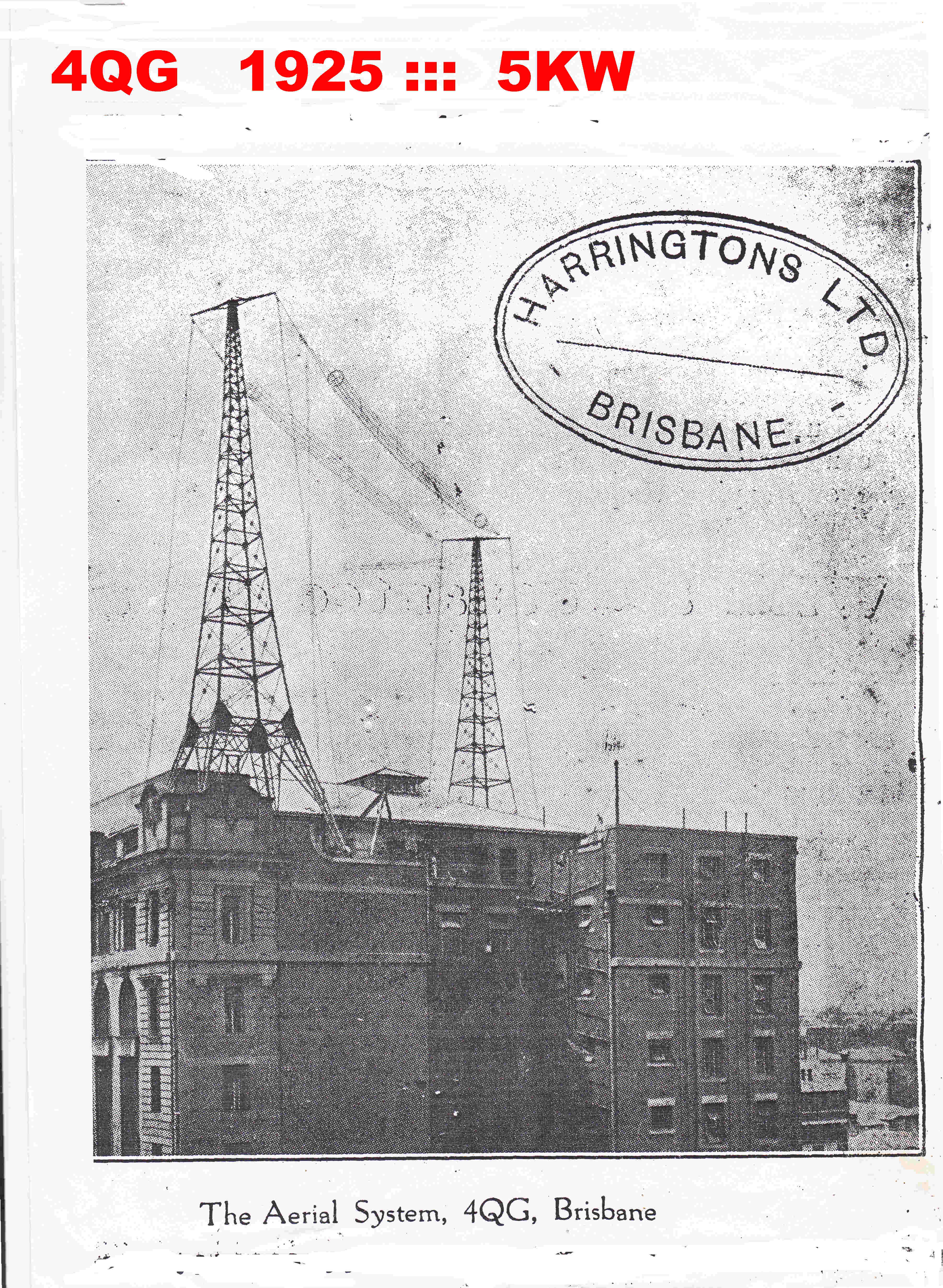
 The 4QG antenna is shown on the right.
It was a typical broadcast antenna for its time - an inverted L.
The steel towers were 100 ft. high and separated by 127 ft. with 17 ft. crossarms.
The four conductors hanging off the "earthy" end of vertical members, together with the
tin roof, probably acted as a counterpoise.
Essentially the antenna was a top loaded monopole with most of the vertically polarised
ground wave radiated from the vertical feed wire.
The steel towers act as parasitic radiators and severly disturb the omnidirectional pattern
of a monopole.
This extract from the transmitter operating manual describes the aerial tuning procedure.
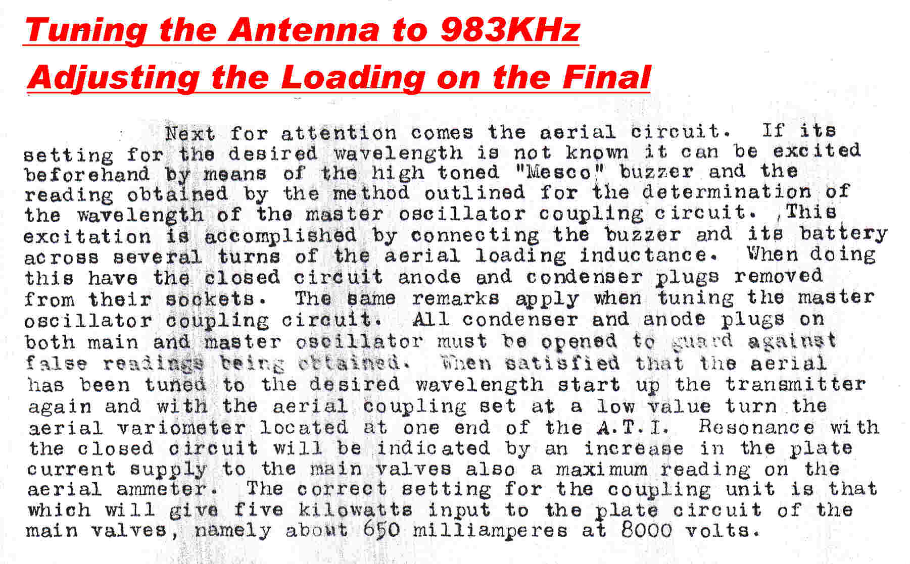
 The MESCO Buzzer is shown on the right.
It was used as a source of wideband test signals for tuning both the antenna and the
tuned circuits within the transmitter.
A metal cantilever clamped at one end vibrates at its natural frequency - usually in the mid audio range.
The vibration is maintained by an electro - magnet which pulls the cantilever
in a direction to break a set of electrical contacts on the cantilever.
To tune the antenna, the "hot" end of the inductance of the electro-magnet is loosley coupled to the antenna by a
small capacitor. An impulsive current recurring at the frequency of cantilever resonance excites the antenna
into it its natural oscillation frequency.
This is monitored by a loosley coupled receiver set to the intended antenna resonant frequency .
The antenna is then tuned for maximum response from the receiver.
The receiver frequency is set using a standard calibrated wave meter using the technique described above.
The wave meter is essentially a stable high Q resonant circuit with the variable capacitor calibrated in
Kcycles/second.
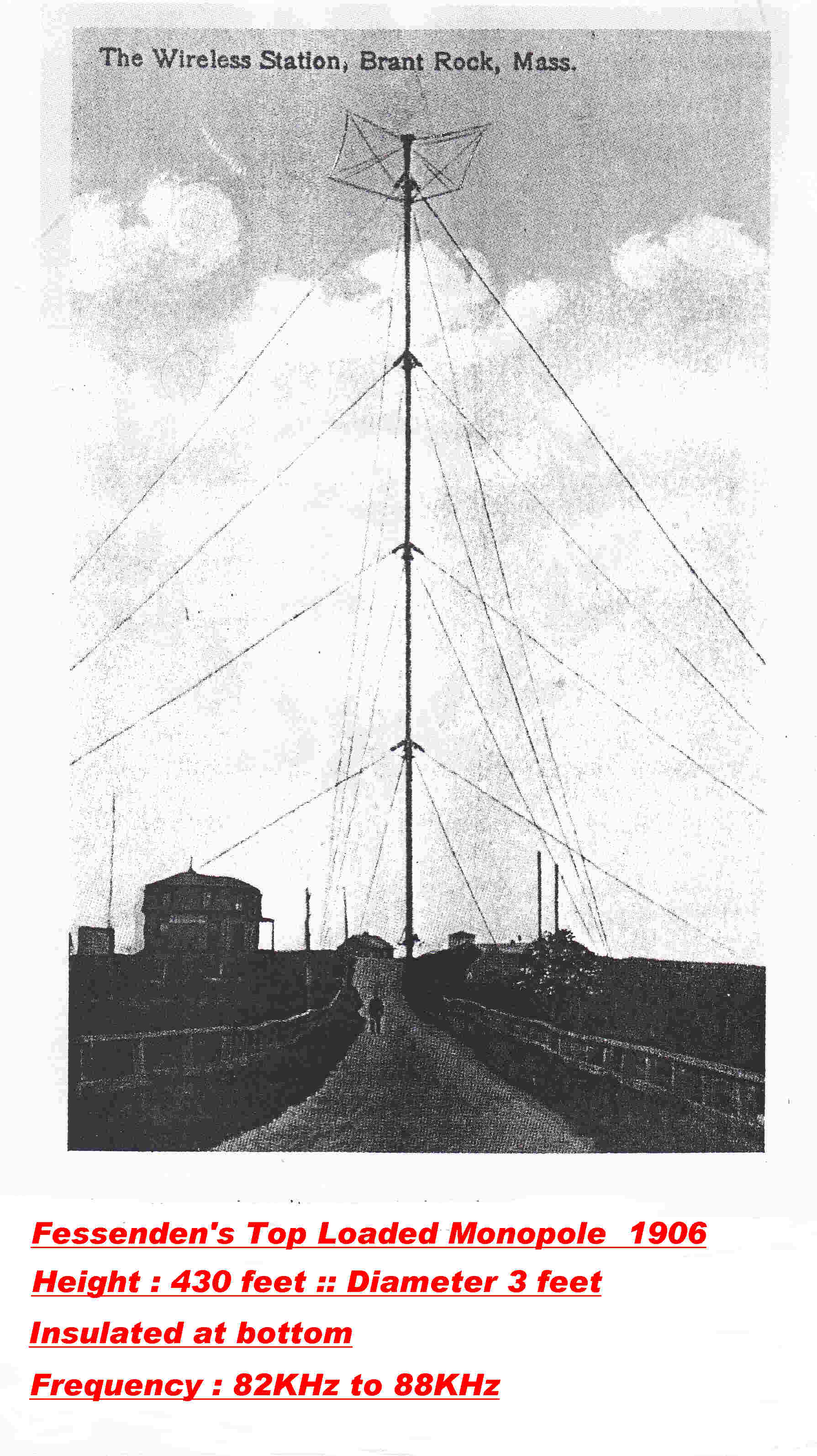 Fessenden's Top Loaded Monopole at Brant Rock is shown on the right.
It is 430 feet high and 3 feet in diameter.
It is believed that the operating frequency was between 82KHz and 88KHz.
It radiated the first AM broadcast on Xmas Eve 1906.
It also radiated the first transatlantic telephony. This was received at Machrihanish in Scotland
in November 1906.
It is a tribute to Fessenden's grasp of Maxwellian field theory.
He understood the difference between the near inductive field and
the field radiated as a ground wave.
It seems amazing that Fessenden's pioneering work on monopoles was forgotten with the adoption of
inverted Ls and Ts for medium wave broadcasting.
It was not until Stuart Ballantine's papers in 1924 that the wonders of mnopoles were reintroduced.
See:-
Ballantine S "On the radiation resistance of a simple vertical antenna in wavelengths below the fundamental"
Proc. IRE 12 1924
Ballantine S "On the optimum transmitting wavelength for a vertical antenna over a perfectly conducting earth."
Proc. IRE 12 1924
THE TRANSMITTER
The transmitter consisted of two MT7A triodes in parallel as a self excited oscillator
driving three MT7A triodes to form the final output stage.
These were plate modulated using the Heising circuit. The modulator consisted of eight MT7B triodes
in parallel operated class A.
The input stage of the modulator was made up of two DE5 triodes in parallel choke coupled
to four DE5 triodes in parallel. These were then choke coupled to the grids of the eight MT7B
modulator tubes.
A six phase rectifier with six Marconi MR7 diodes provided the 8KV high tension.
The MT7A and the MT7B differed only in the grid pitch - the MT7A had a mu of 80 -
MT7B a mu of 40.
The filaments were bright emitters drawing 10 amps at 15 volts.
The transmitter was supplied and installed by AWA.
The transmitter was taken over by the ABC - The Australian Broadcasting Commision -
on Friday 1st July 1932.
It was modified by the technical staff of the PMG's depatment.
The three MT7As in the RF output stage were replaced by a single water cooled triode.
By the late thirties it was possible to measure the performance:-
Frequency Response: -6db at 50Hz : -4.5db at 5KHz
Distortion: 7.5% : Frequency 400hz : Modulation Depth 80% *
These figures are not good but they are still much better than the performance of imported
AM receivers today.
One I recently checked had a cutoff frequency of 1.8KHz.
* Note: All transmitter performance figures are taken from the unpublished text on
Queensland Broadcast History by Doug Sanderson.
Audio Coupling Networks
The coupling networks in all stages of the modulator were :-
Anode Load: 100H choke
DC Block: Coupling Capacitor : Usually about 1uF
Grid Leak or Bias : 100H choke
The bias and plate current on all tubes was set manually.
Setting the plate current too high with a resistive load may "bottom" the stage and
render it inoperative. Inductive loads prevent this.
Grid current on audio overloads during overmodulation may charge the coupling capacitor
in a negative direction. This may paralyse the stage and take some time to leak away
with a high value grid leak resistor.
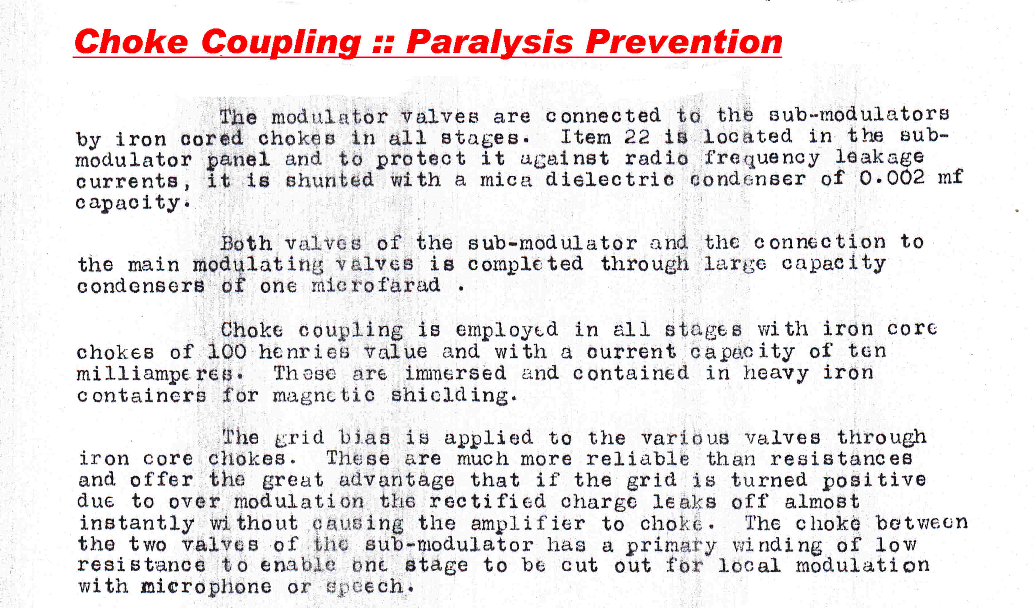
This extract from the transmitter operating manual indicates that the transmitter designers were well aware of this in 1925.
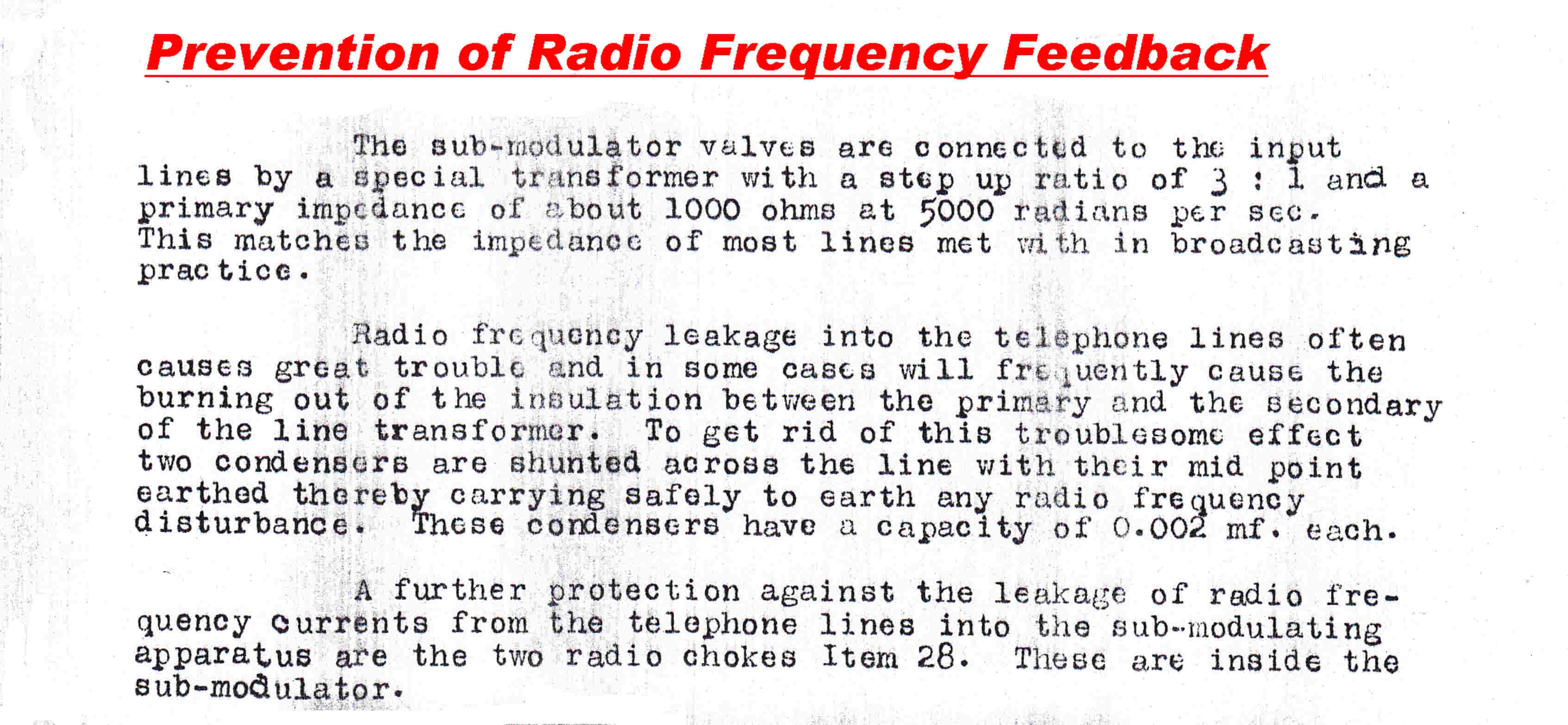
RF Pickup and RF Feedback
With the transmitter and studios situated just below the antenna,
severe RF pickup and RF feedback would be expected.
This extract from the operating manual indicates that this was indeed the case.
 THE HEISING MODULATOR
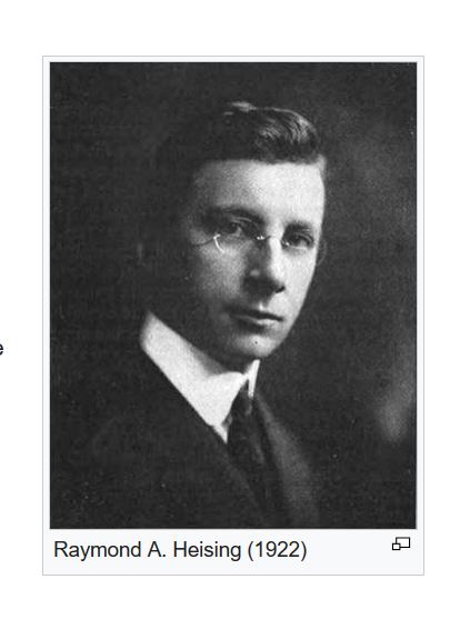
The simplified circuit of a Heising modulator is shown below.
It was developed by Heising at Bell Labs and was the first form of plate modulation
extensively used in broadcast transmitters of the 20's.
See: R A Heising "Modulation in Radio Telephony" Vol 9 pp 305-352 1921
The modulator tube is operated class A and the RF output tube class C.
A large inductor with a high reactance for all modulation frequencies is included
in the common plate supply of both tubes.
This results in the following:-
[1] The RF amplifier forms a resistive load on the class A amplifier.
This load may not be linear.
[2] Any change of the plate current of the modulator produces an equal and opposite
change in the average plate current of the RF stage.
[3] The HT input current is constant, so the input power is constant.
[4] The plate dissipation of the class A amplifier decreases with modulation.
Since the input power is constant, this results in an increase of input power to
the class C stage.
[5] Some of the increased power input to the RF stage is diverted into sideband power,
the remainder into increased plate dissipation.
At carrier cutoff the effective plate voltage on the RF stage should be 0, with the
grid of the class A stage just reaching 0 volts.
Under this condition the class A amplifier has its maximum plate current.
To support this, the clss A stage must have adequate plate voltage.
The voltage drop across a heavily bypassed resistor fulfills this condition.
The quiescent plate current of the class A stage must at least be equal to the plate current
of the RF stage under carrier conditions. Further, its plate voltage is greater than that
of the RF stage, the dissipation high and the efficiency low.
This explains why there are three tubes in the RF output stage and eight in the modulator.
To overcome the efficiency problem the class B transformer coupled modulator was developed
by Loy E Barton ::
A Plate Modulation Transformer for Broadcasting Stations : University of Arkansas
Bulletin Vol.23 May 1930
This was not altogether a blessing:-
[A] A very large modulation transformer together with a modulation choke were required.
[B] A nasty form of distortion - crossover - was introduced by the class B output stage
of the modulator
[C] The transfer function of the modulation transformer and capacitively coupled choke was
not conducive to envelope feedback.
The leakage reactance and winding capacity caused stability problems at high frequencies -
the DC blocking capacitor and choke at low frequencies.
Without envelope feedback the overall linearity, then, was heavily dependent on the plate
modulation process in the final stage.
Alas this is not inherently linear.
It depends on the RF load, the RF drive and the tube characteristics.
If power output is sacrificed, plate modulation can be made linear by choosing a large RF load
so that the tube is "bottomed". The RF in the plate must then swing between the HT
voltage and very nearly zero, so the RF envelope tracks the instantaneous HT voltage.
This technique was frequently used when the modulation was at a low level followed by
class B linears. Here efficiency was uninportant because of the low level - linearity
was important.
[D] The class B output stage draws a variable output current from the power supply filter.
The induced low frequency transients can be a problem.
On the other hand, all RF stages except the final ran in a bottomed or saturated condition;
the transmitter was relatively efficient and, lastly, was usually better than the majority
of receivers.
It is difficult to imagine a station owner overly concerned with the exact distortion figure
to cater for the few with wideband low distortion tuners.
There is at least one exception to this -- WLW.
R J Rockwell - Cathanode Modulation System :IEEE Transactions on Broadcasting
- Vol BC13 Number 1 - Jan. 1967 - pp 19 - 30.
The circuit of the Heising Modulator is shown below:-

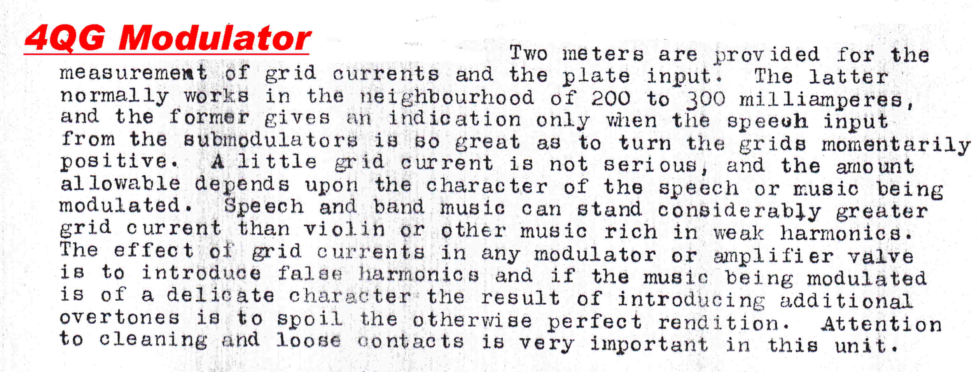
The modulation level was set by increasing the audio input to the transmitter
until the class A output stage of the modulator just ran into grid current on peaks.
The following extracts are from the 1925 transmitter operating manual. It would appear
that distortion on Jazz was considered of little consequence.

A second program for the ABC was started in Brisbane on Friday 7th June 1938
with the call sign 4QR - 4 for Queensland and QR for Queensland Regional.
Programs were mostly relayed from Sydney over something like 600 miles of
open wire line. These usually had a sharp cutoff frequency of 5KHz. and were sited beside
railway lines.
Vacuum tube repeater amplifiers were situated in the local country post office exchanges
about 50 miles apart.
The transmitter was situated in the central telephone exchange in Elizabeth street
opposite the Catholic Cathedral.
The radiator was a single tower on the roof of the building.
The installation illustrates the enormous strides made in both vacuum tube
and circuit technique since the 4QG transmitter in 1925.
The transmitter was designed and manufactured by STC in Sydney.
Some developments in the thirteen years between 1925 and 1938 :-
[1] The invention of the tetrode, the beam power tetrode and the pentode.
With pentode audio stages in the modulator, R-C coupling replaced transformer and
choke coupling. This greatly improved the frequency response and removed low frequency
distortion due to non-linearities in the B-H curve of the iron.
It gave an overall forward transfer function much more ameniable to
envelope feedback.
The almost complete plate - grid shielding in the pentode greatly improved
the performance of the oscillator and low level RF stages.
Difficulties in cooling the screen grid precluded pentodes from high power stages.
The low power pentode in the 4QR transmitter was the 6C6 - a six pin pentode with
the grid brought out on top. The octal version of this - the 6J7 - was used universally for
low level audio stages such as microphone amplifiers.
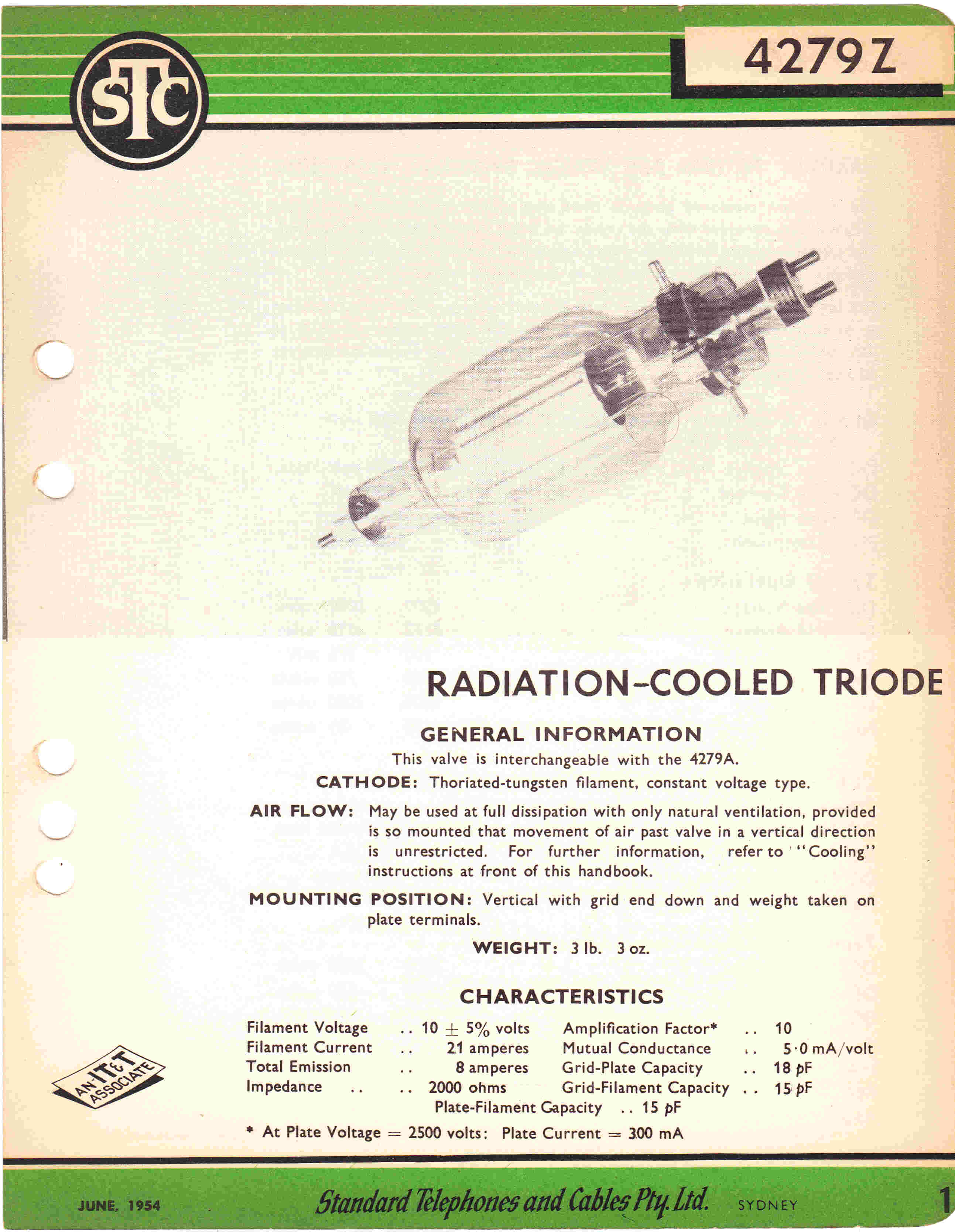
The RF output stage consisted of four 4297 triodes in parallel push-pull.
The change from a bright tungsten emitter in the MT7A to a thoriated tungsten filament
in the 4279 resulted in a saving in filament power.
New materials allowed the grid to be placed closer to the cathode, resulting in a
higher Gm, lower drive power and higher stage gain.
[2] The indirectly heated oxide coated cathode.
The electrical separation of heater and cathode now freed up the cathode as another
control element for the tube.
Self bias ( cathode bias ) was now possible, thus dispensing with bias batteries.
More importantly, cathode bias provided DC negative feedback over the quiescent
operating point of the tube, resulting in freedom from drift in performance.
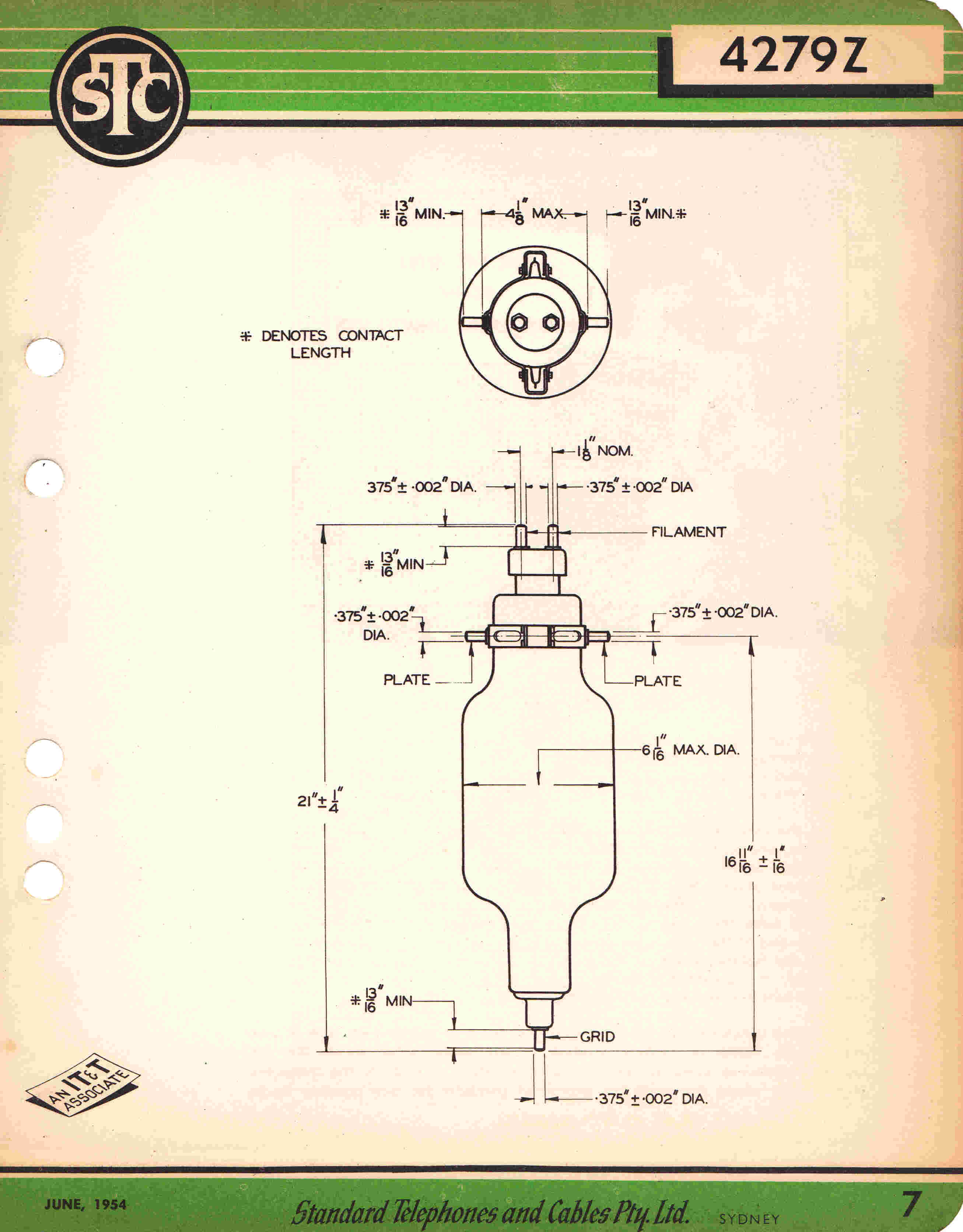
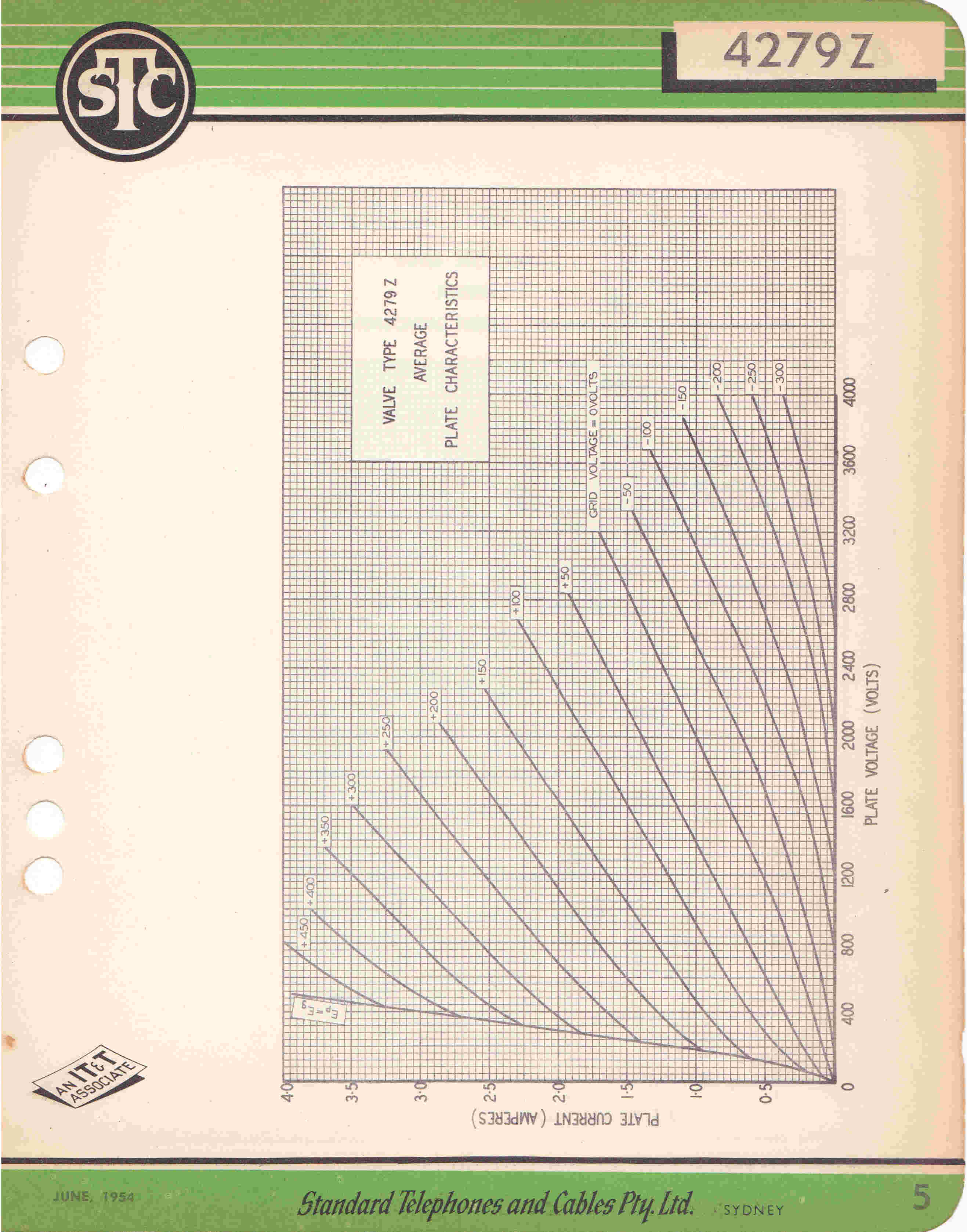
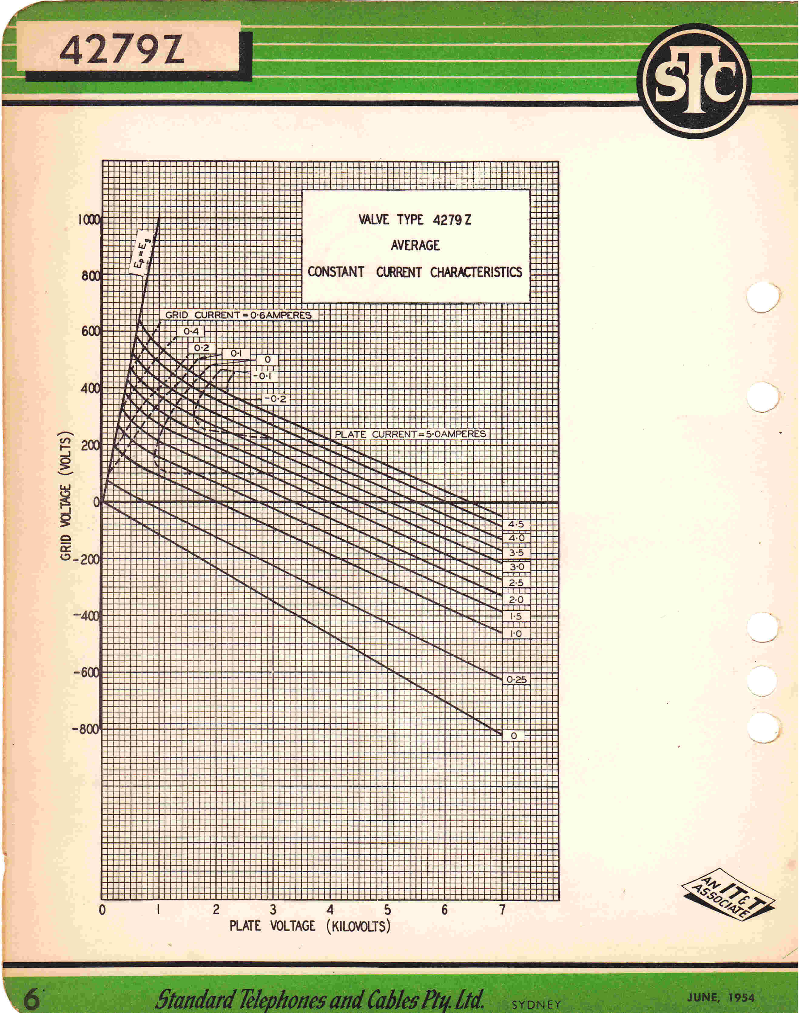
[3] The 4279 Triode - The Output Tube of the First 4QR Transmitter 1938
|
|
|
|
|
Plate Characteristics |
Constant Current Characteristics |
By 1938 there had been a great change in transmitter circuit
topology from the start of 4QG in 1925.
Heising modulation had been abandoned because of low efficiency and the large
number of tubes required in the class A modulator.
Two competing systems emerged:-
[A] High level plate modulation of the final RF stage by a large class B audio amplifier.
The audio amplifier output was at least half the carrier power of the transmitter
and required a large output transformer and DC carrying choke.
This topology was developed by Loy E Barton of Arkansas University and further developed
and marketed by RCA.
An outline of some of the features of high level modulation given above is worth repeating here:-
[A] A very large modulation transformer together with a modulation choke were required.
[B] A nasty form of distortion - crossover - was introduced by the class B output stage
of the modulator
[C] The transfer function of the modulation transformer and capacitively coupled choke was
not conducive to envelope feedback.
The leakage reactance and winding capacity caused stability problems at high frequencies -
the DC blocking capacitor and choke at low frequencies.
Without envelope feedback the overall linearity, then, was heavily dependent on the plate
modulation process in the final stage.
Alas this is not inherently linear.
It depends on the RF load, the RF drive and the tube characteristics.
If power output is sacrificed, plate modulation can be made linear by choosing a large RF load
so that the tube is "bottomed". The RF in the plate must then swing between the HT
voltage and very nearly zero, so the RF envelope tracks the instantaneous HT voltage.
The same technique is used in solid state transmitters using saturated MOS fets. They have the
advantage of no conductive input current corresponding to grid current in a tube.
This technique was frequently used when the modulation was at a low level followed by
class B linears. Here efficiency was uninportant because of the low level - linearity
was important.
[D] The class B output stage draws a variable output current from the power supply filter.
The induced low frequency transients can be a problem.
Normally the class B output stage and the modulated RF output stage share the same power supply.
The voltage drop caused by the increased HT current demanded by the class B stage at full
modulation decreases the carrier level. This is known as carrier shift and is not desirable.
On the other hand, all RF stages except the final ran in a bottomed or saturated condition;
the transmitter was relatively efficient and, lastly, was usually better than the majority
of receivers.
[B] Low level modulation - usually grid - followed by class B linear amplifiers.
Heavy envelope feedback was usual in these transmitters.
The design was adopted by Western Electric.
Although inefficient, I believe that they had the "cleanest" sound of any transmitter
in the vacuum tube era.
In a class B linear, "room" must be made to allow the RF swing on the plate
to double over the swing during carrier conditions. This means that the plate currnt pulse
(180 degrees wide ) occurs at a high plate potential, causing increased plate dissipation
and low efficiency.
The DC input power is constant with modulation and the behaviour is similar to a class A
audio output stage.
The plate dissipation decreases with modulation to supply the increased output power.
The transfer characteristic of a class B output stage is S shaped similar to a push pull
class A output stage. The curve is smooth about carrier level, and does NOT introduce
the equivalent of crossover distortion found in a class B audio modulator.
The transfer function is also friendly to the application of overall feedback.
It is, effectively, DC coupled for the modulation.
A change in the input to the low level modulater causes a long term change in the output
of the envelope detector driven from pickup from the final tank circuit -
DC coupling.
Simple matching networks between stages resulted in repeated single high frequency poles
in the forward transfer function.
The heavy envelope feedback causes the transfer characteristic around carrier level
- the middle bit - to be highly linear.
Since the modulation level was usually less than in modern practice, the signal spent
most of its time in this region, with consequent very low overall distortion.
Heavy envelope feedback is not without problems.
During negative modulation peaks causing carrier cutoff, the gain of the class B linear
stages - that is the gain of the forward path - goes to zero. Large error signals build up
in the feedback loop and these can cause paralysis if no preventitive action is taken.
It would seem that all attempts to improve the efficiency of a class B stage result in increased
distortion and difficulty in adjustment.
For instance, the Doherty high efficiency amplifier introduces cross over distortion.
A second output tube is turned on for the positive modulation cycle, and the load on the
"carrier " tube falls. It is almost impossible to avoid a kink in the transfer characteristic-
mimicing crossover distortion in a class B amplifier.
Grid modulation has a number of desirable features in a transmitter
modulated at a low level.
[A] If the grid is not driven positive it requires virtually no driving power,
and so may be driven from a class A audio stage.
[B] R-C coupling can be used without any transformers or chokes, so that high
bandwidths are possible.
This facilitates the application of overall envelope feedback.
Even with idealised vacuum tube characteristics, grid modulation
is inherently non-linear.
Suppose we have an idealised vacuum tube with a sharp cutoff and a linear relation between
plate current and grid voltage.
If we suppose a normalised modulation input, k, to the grid where:-
k = 0 on the negative tip of the modulation cycle.
and the plate current pulse has just reached an angle of 0 degrees and the
current magnitude is 0.
k= 1 on the positive peak of the modulation cycle.
and the plate current pulse angle is +(-)90 degrees, +(-)Π radians, and
the plate current pulse has a magnitude of I.
Note: k varies linearly with modulation drive.
For the idealised grid modulation described above, we have the basic equations:-
i = I [ cosΦ - cosΘ ] for -Φ < Θ < Φ --------(1)
i = 0 otherwise
cosΘ = 1 - k
sinΘ = [ 1 - ( 1 - k )2 ]1/2
= [ 2k - k2 ]1/2---------(2)
Substituting (2) in (1)
i = I [ cosΦ - ( 1 - k ) ]
We now evaluate the fundamental plate current using Fourier:-
If = [1/Π][ ∫ i cosΦ dΦ ]
between limits - Θ to Θ
Because the plate current pulse is symmetrical we can then write:-
If = [2/Π][ ∫ i cosΦ dΦ ]
between limits 0 to Θ
Substituting for i we get:-
If = [2I/Π][ ∫[ cos2Φ - ( 1 - k )cosΦ ] dΦ
between limits 0 to Θ
If = [2I/Π][ ∫[ ( cos2Φ + 1 )/2 - ( 1 - k )cosΦ ] dΦ
between limits 0 to Θ
Integrating:-
If = [2I/Π][ sin2Φ/4 + Φ/2 -
( 1 - k )sinΦ ]0Θ
If = [2I/Π][ sin2Θ/4 + Θ/2 -
( 1 - k )sinΘ ]
If = [2I/Π][ 2 (sinΘcosΘ)/4 + Θ/2 -
( 1 - k )sinΘ ]
Substituting for cosΘ and sinΘ
If = [2I/Π][ ((2k - k2 )1/2)( 1 -k )/2
+ (cos-1( 1 - k))/2 - ( 1 - k )( 2k - k2 )1/2 ]
If = [I/Π][ cos-1( 1 - k) - ( 1 - k )( 2k - k2 )1/2 ]
for 0 < k < 1
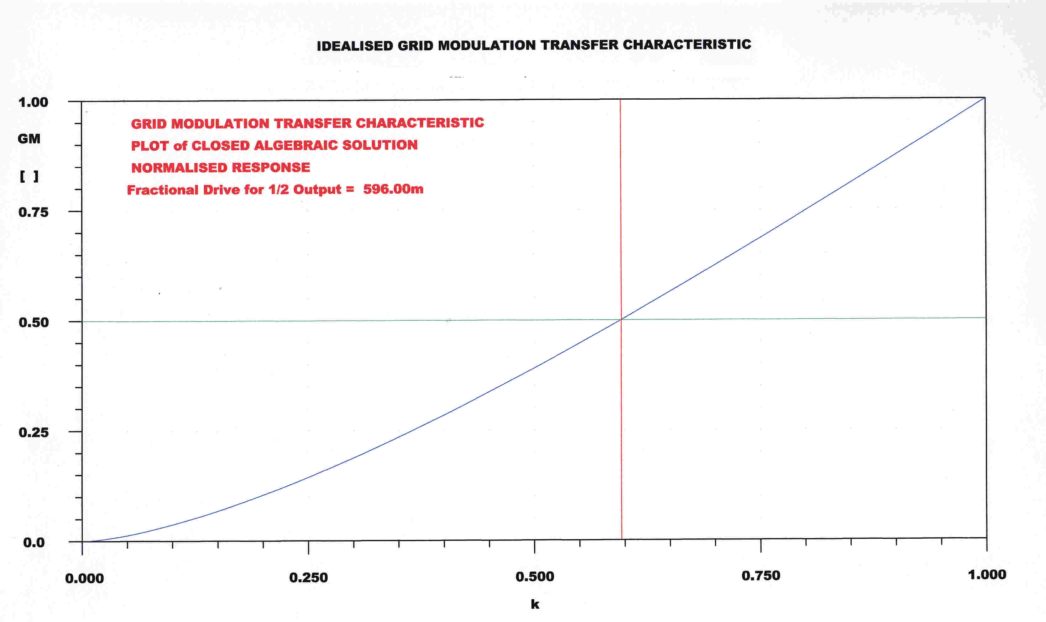 A plot of the grid modulation characteristic from the above equation is shown opposite.
It has been multiplied x2 to normalise it so that:-
I f = 1 when = 1
From the asymmeytry it would appear that the distortion is predominantly
second harmonic and is far less than distortion encountered in the class B "linears".
In reality, the lower part would suffer greater curvature due to the tube characteristics
at low current.
The best discription of the first 4QR transmitter comes from the
history written by Doug Sanderson.
A direct copy is given below:-
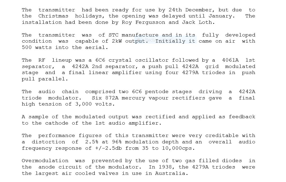
The response and distortion figures are unusually good
for 1938.
It is doubtful if any AM tuner at the time could do the transmitter justice.
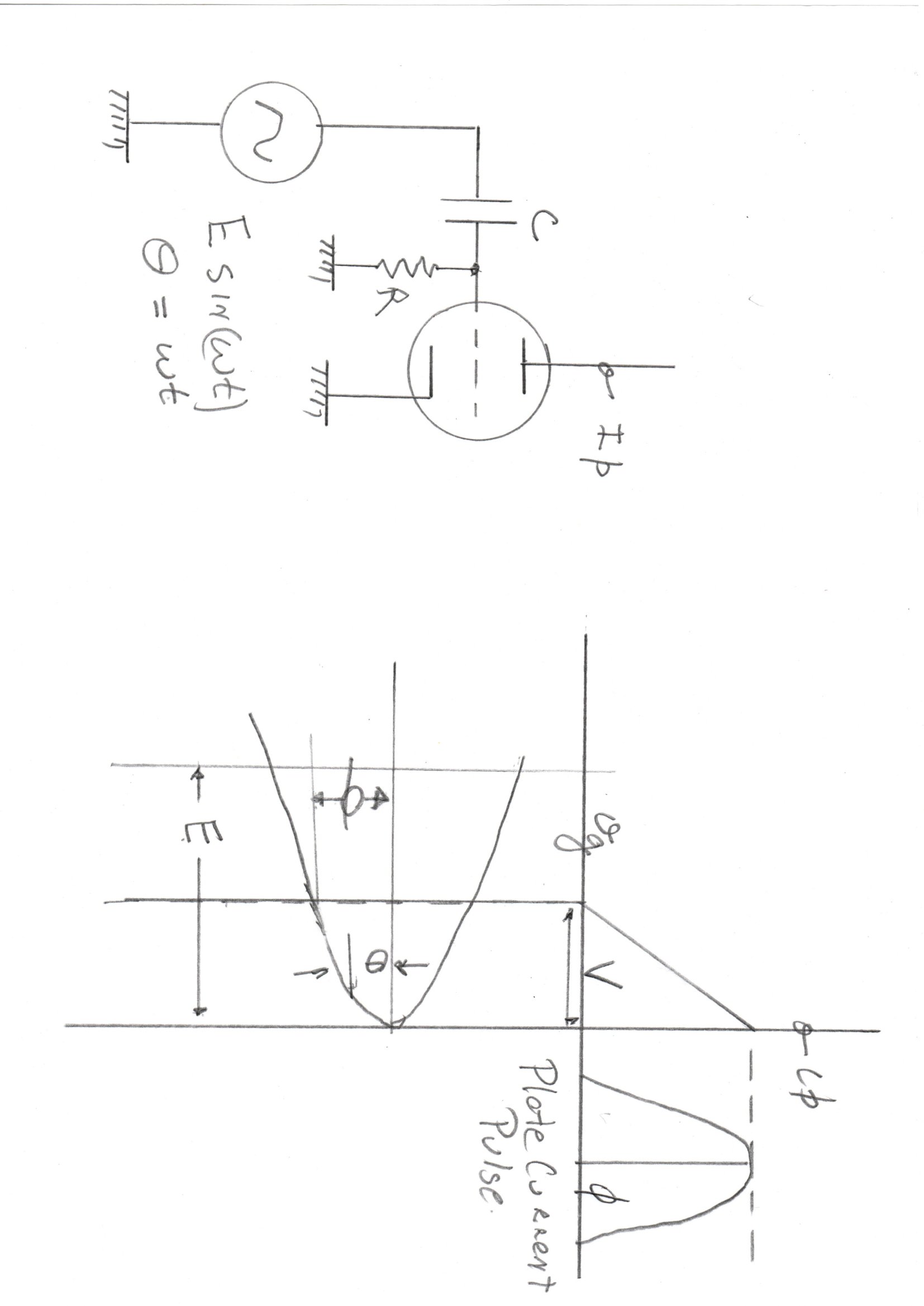
Grid Leak bias was widely used in vacuum tube transmitters, yet analysis of its detailed
behaviour are not usually given
Analytic solutions are possible with some simplifying assumtions.
The assumptions are:-
[1] The plate current is a linear function of grid voltage above cutoff.
[2] The grid cathode diode has a high perveance, and so the grid is always driven just to zero volts.
An algebraic analysis gives an excellent insight into the behaviour of a stage with grid leak bias as the
sinusoidal drive is increased.
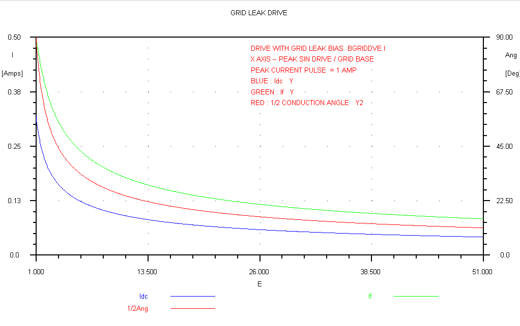
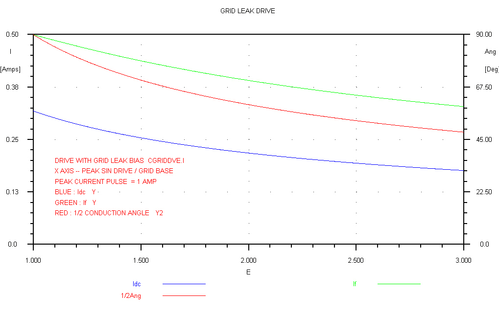
 The curves for a linearised grid leak stage are shown on the right.
-V = Tube cutoff voltage
E = peak of sinusoidal drive which is: E cos( 2 PI f t ) = E cos( Θ )
Φ is the half conduction angle
Θ = 2 PI f t = general time variable for the sinusoidal drive
I = peak of the current pulse (the plate current at zero bias)
Idc = DC plate current
If = peak fundamental of plate current
We have the equations:-
cos( Φ ) = 1 - V/E
Φ = arccos( 1 - V/E )
Idc = [ I/PI ] [ 1/( 1 - cos( Φ ) ) ][ sin( Φ - Φ cos( Φ ) ) ]
If = [ I/PI ] [ 1/( 1 - cos( Φ ) ) ] [ Φ - 0.5 sin( 2 Φ ) ]
A plot of these curves is given with I = 1
The Y axis can then be modified for any zero grid plate current by multiplying by that current.
For instance, if a 6V6 has a plate current of 100Ma at zero bias, the Y axis is multiplied by 0.1
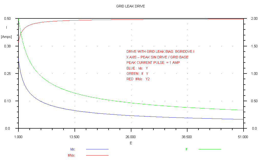
A general overview of the behaviour of grid leak biased stages is shown below:-
The drive is taken out to 50 times the grid base to show the asymptotic behaviour.
|
|
|
A peak drive of 50 times the grid base is unrealistic, but the above curve is plotted
to show that the variables Idc, If and Φ vary only very
slowly as the drive is increased |
Thr ratio If/Idc is plotted in this curve. |
The plot for V/E in the range 1 to 3 covers the conditions found in most transmitters.
|

|
|
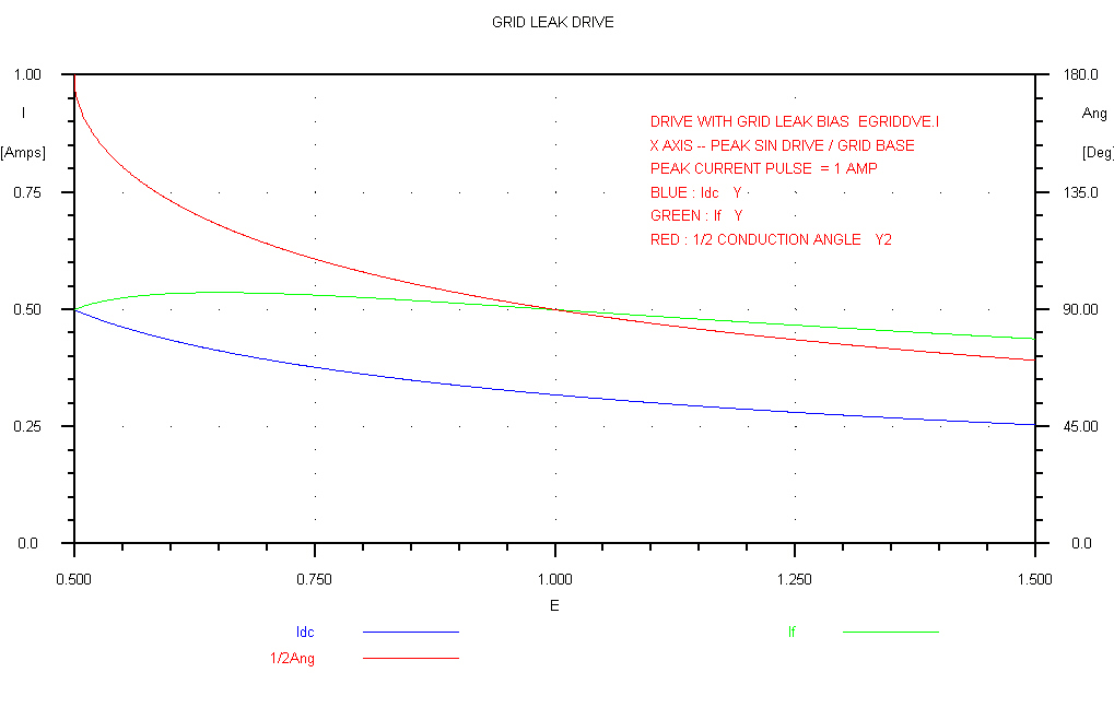
The angle Φ is plotted in this curve |
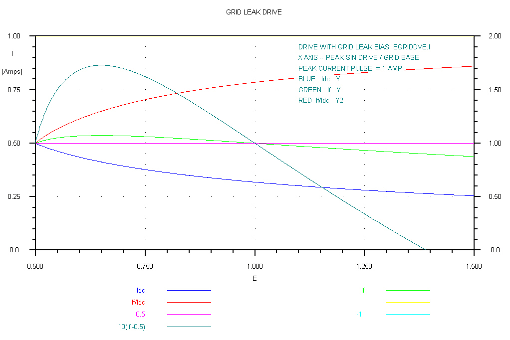
The ratio If/Idc is plotted in this curve |
For V/E = 0.5 the stage is a fully driven class A stage.
It transforms to a class B stage for V/E = 1
|
|
|
Note that the variable If has a maximum at about 0.62. |
In this graph the maximum has been multiplied by 10 |
General MacArthur set up his headquarters in a building
at the corner of Edward and Queen street in Brisbane.
The 4QR transmitter and mast were in the same block, with 4QG in the
Treasury building only a few blocks away.
It was feared that the transmitters would become a homing beacon for
Japanese bombers, so both were removed.
A permanent home was found for two new transmitters for 4QR and 4QG
at Bald Hills North of Brisbane.
4QR - 590KHz 10KW - was modulated at low level with a water cooled
final RF amplifier.
4QG - 790KHz 10KW - was plate modulated and air cooled.
Both transmitters were designed and manufactured by STC in Sydney.
Their output was carried in separate 200 ohm open wire lines to the matching and
diplexing hut at the bottom of the mast.
Two short wave transmitters, VLM and VLQ, were mirror images of the broadcast
transmitters and carried the same programs.
Low level audio processing - line equalisation, compressor amplifiers,
limiters, and 10KHz low pass filters were housed in a room near the front porch
- well away from the transmitter finals.
RF pickup is always a problem at transmitter sites.
4QR had peak limiting but no compressors, since it broadcast classical music.
4QG had both peak limiting and compression.
Programs were relayed to the site by 600 ohm overhead lines.
The 10KW 4QR and 4QG transmitters began diplexed operation on the monopole
antenna on 1st September 1948.
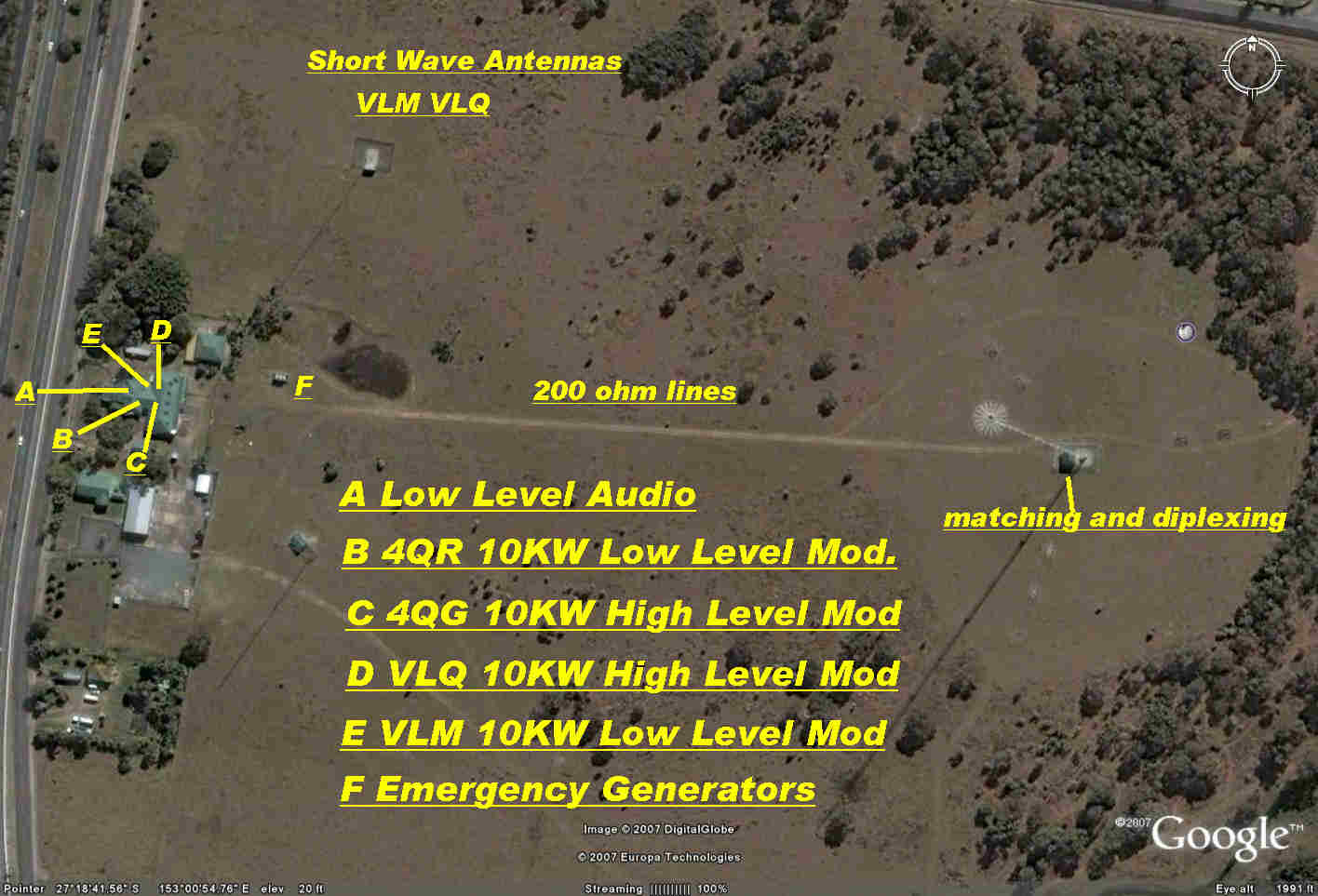
Below I have superimposed my memory of the site sixty
years ago on a modern Google map.
The transmitter building was in the form of an H with the four transmitters
placed symmetrically along the arms of the H.
The general design was of a high standard and speaks volumes for the
engineers and technicians who designed and maintained the National
Broadcasting System.
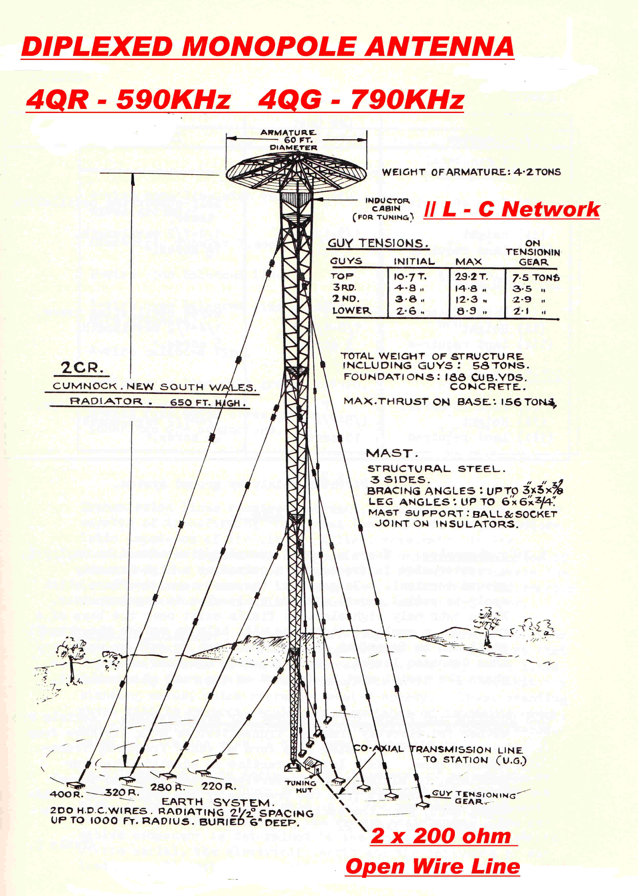 A drawing of the monopole mast and earth system is shown opposite.
Note: This and the other drawings are taken from a PMG training manual.
The original paper describing the electrical design of the mast is:-
Dual Frequency Operation of a Loaded Vertical Medium Frequency Radiator
by A. J. McKenzie, W. H. Hatfield, V. F. Kenna
IRE Australia January 1955
It would appear that this design was adopted as a standard
for the National Service.
It represents the development of the monopole radiator in its final form:-
[A] The mast has now become the radiator. The current is carried by the steel
structure of the mast. In later designs the current was supported by
three copper conductors running the full length of the mast and held off by
insulators on each corner.
This reduced the losses and increased the bandwidth by effectiveely
increasing the side dimensions. (See below)
It also decreased the possibility of cross-modulation between the
two transmitters.
The rust in the contact between riveted steel joints can produce
non-linear junctions, and so cross modulation.
[B] A large low loss earth plane is formed by radial wires at the base.
As shown on the drawing, the earth wires are spaced at 2.5 degrees,
1000 feet long, and buried about 6 inches deep.
The system approximates a perfectly conducting plane, so the monopole
"sees" a reflection of itself to produce a dipole.
The input impedance between the base of the monopole and the earth plane is half
the input impedance of the dipole, and the radiation pattern above ground
is the same.
Swampy locations are usually chosen for AM stations to increase the
soil conductivity and further decrease losses.
[C] The monopole is energised by a voltage generator between the base of the mast and
the earth plane.
[D] The 8 foot triangular sides are large enough to give adequate bandwidth.
Intuitively, it can be seen that bandwidth depends on the the ratio of the energy
radiated per cycle to the energy stored per cycle. To change states, the stored
energy must be radiated and the less the stored energy, the more quickly
this can occur. The higher the speed, the greater the bandwidth.
Now the stored energy Es is given by :-
Es = ∫∫∫ [ E.D + B.H ] dv where:-
E = electric field strength vector
D = displacement vector
B = magnetic flux density vector
H = magnetic field strength vector
and the volume integral is taken over the all space outside the mast.
Now the field consists of two components - the induction field and the radiation field.
The induction field varies as (1/d)2 and (1/d)3 and so predominates
near the mast and contributes most of the energy given by the above triple integral.
d = distance from the mast
Even small increases in the lateral dimensions of the mast eat into the available volume
for the above integral where E D B H are very large,
and so decrease the stored energy with a consequent increase in bandwidth.
[E] The length, L, chosen to favour ground wave over sky wave.
This comes about when L = 0.625 x wavelength.
The radiator is to be used at two frequencies and, obviously, this
condition can only be realised at one frequency.
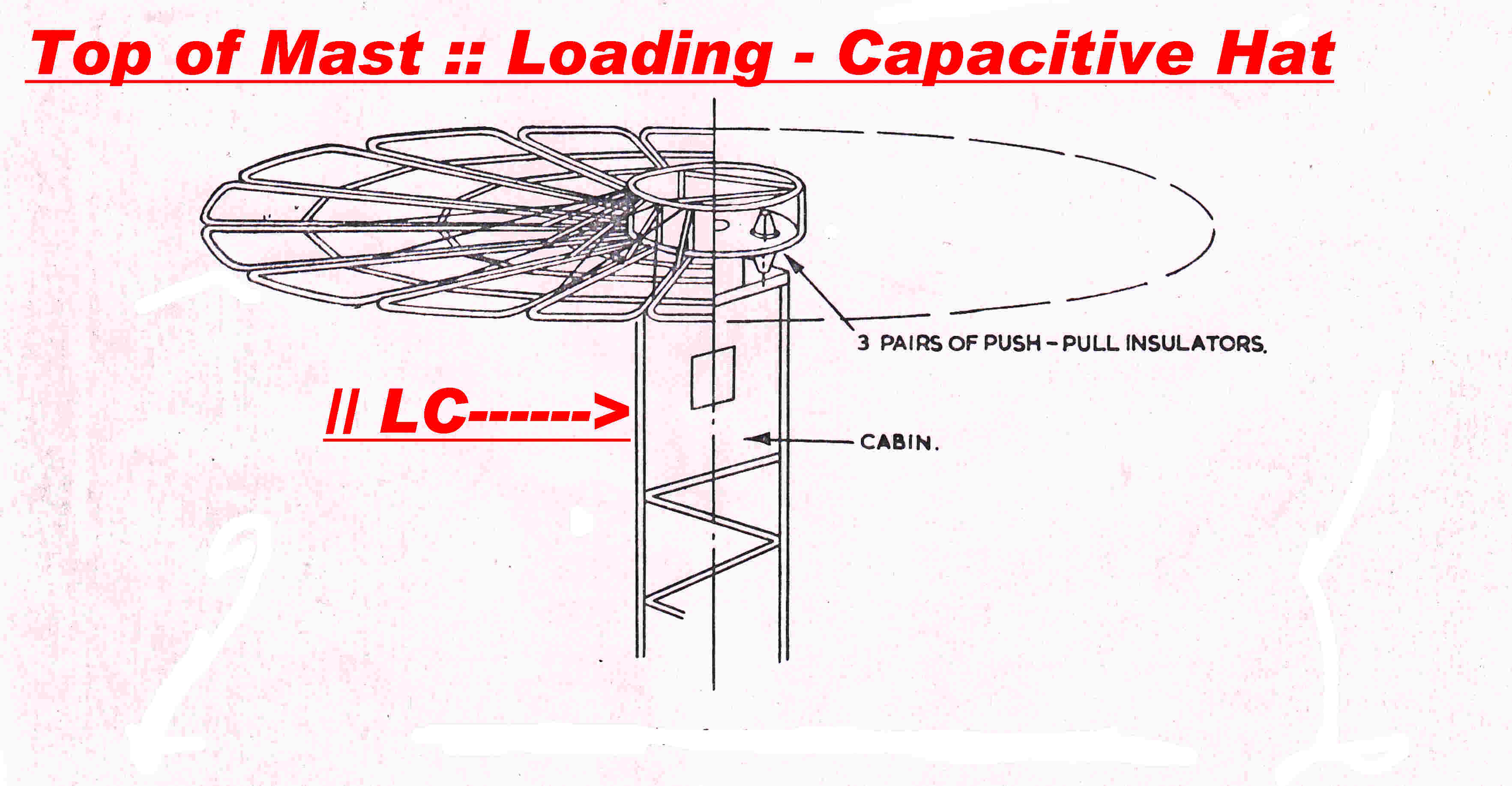
A capacitive hat separated from the top of the antenna by an
L-C network provides the solution.
It has the same capacitive input impedance as an extended length of mast,
and so pulls the standing wave pattern up the mast as would exist
with a higher mast.
The capacitive hat is not a direct replacement for the missing mast,
since it does not contribute to ground wave radiation.
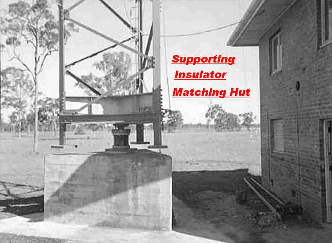
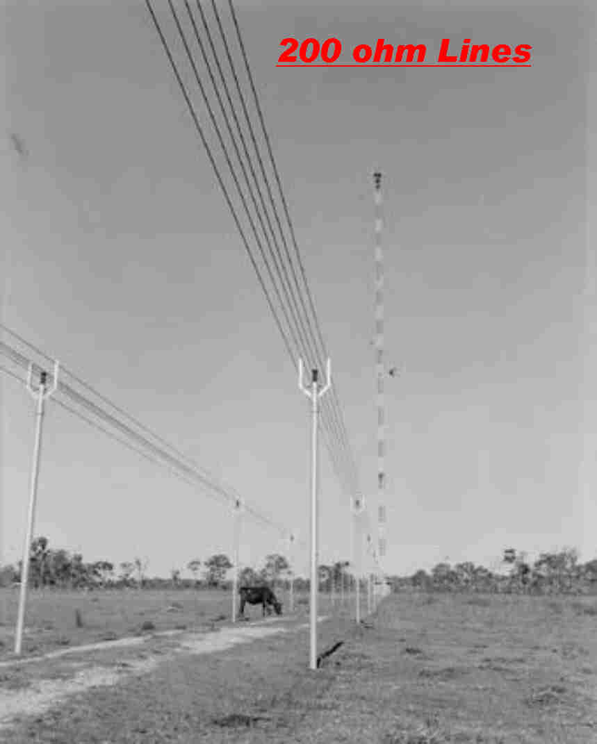
Details of the bottom of the mast and the open wire transmission lines between the transmitters and the matching- diplexing hut are shown below.
|
|
|
The mast pivots on a ball on top of the supporting insulator. |
The 200 ohm open wire line between transmitters and matching hut. |
The problem of diplexing a monopole antenna divides into two parts:-
[A] Producing the optimum current distribution along the mast for both frequencies.
[B] Isolating the output of the two transmitters.
A is achieved by placing a lumped L-C network between the top of the tower and
the capacitive hat.
The input impedance of this network then sets the optimum position for the maximum of
the current standing wave at both frequencies.
B is achieved by lumped L-C isolating networks between the base of the tower
and the matching networks.
Frequently, some of the matching occurs in the isolation networks.
Circuit concepts such as the capacity of the armature to the mast are
used as an intuitive aid in the design.
Since most of the dimensions are a significant fraction of a wave lengtgh,
circuit theory breaks down and it is not surprising that predicted values for the
L-C network were wrong. The analysis should come directly from a solution of
Maxwell's equations.
This is now possible with digital computers.
There is another way of looking at this:-
In circuit theory the approximation: E = -∇V
replaces the general case:-
E = -∇V - μ∂A/∂t
where E is the electric field strength, V is the scalar potential,
and A is the vector potential.
The mast and "capacitive hat" are a distributed system with dimensions
a significant fraction of a wave length, so the vector potential term
μ∂A/∂t cannot be neglected.
From the original paper cited above, the following initial assumptions
using circuit theory were made:-
(1) Free space capacity of hat: 980pF
(2) Capacity of hat to mast: 109pF
(3) Characteristic Impedance of Mast 250 ohms
|

|
|
Some of the hat to mast capacity is made up of the capacity of the three
isolating insulators. |
The inductor was adjustable with 22 turns of 1/2 inch diameter copper tubing:
diameter 18 inches and length 27 inches. |
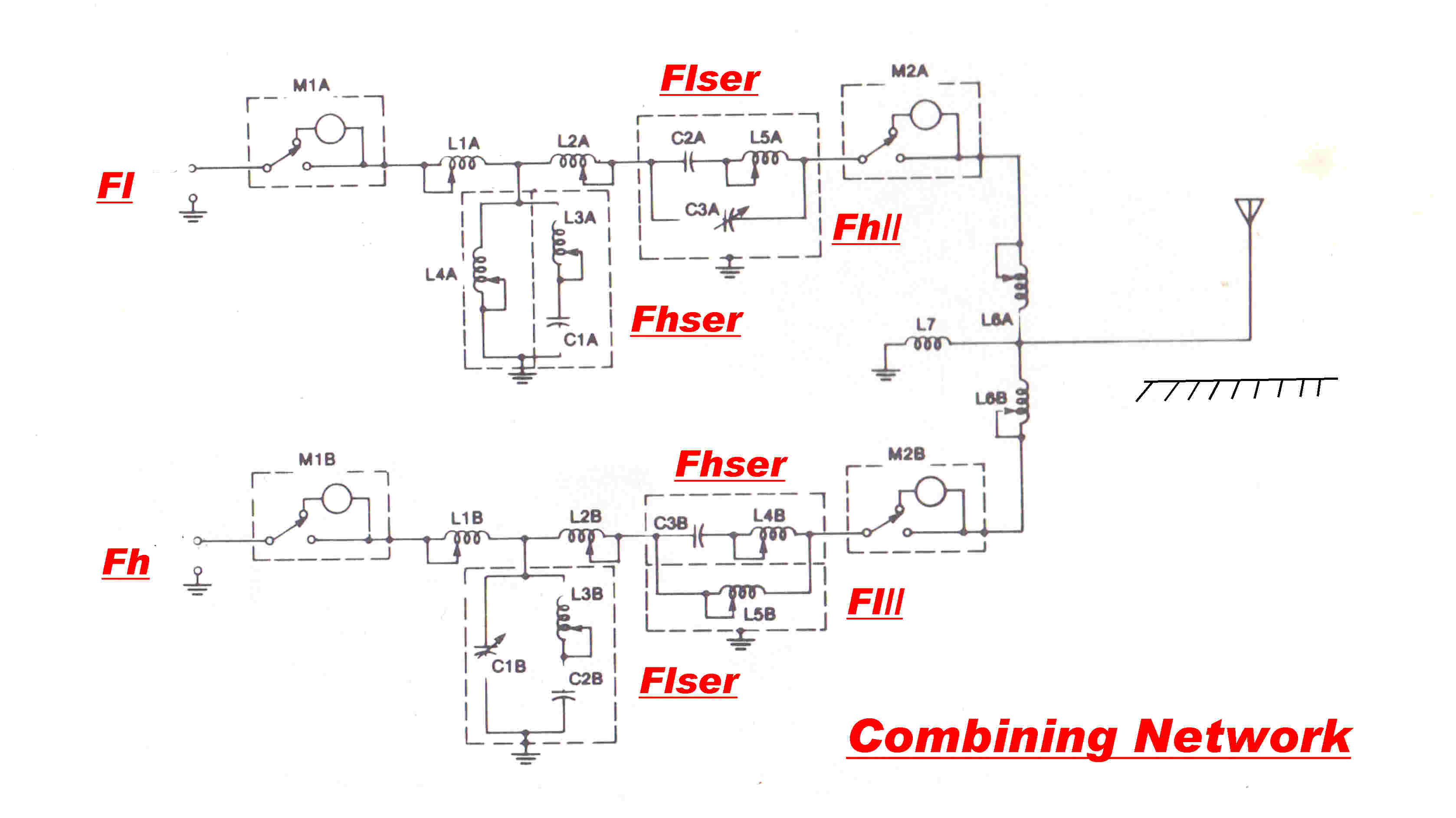 A typical combining network for the operation
of two transmitters on the one monopole antenna is shown opposite.
Fl is the lower frequency and Fh the higher frequency.
The capacitive hat and associated network produce a seies input impedance at
the bottom of the mast equivalent to a capacitor in series with a resistor.
This holds for both Fl and Fh.
L6A cancels the capacitive reactance at Fl and L6B at Fh.
The reactance of L7 is
large and provides an electrostatic drain to earth and a method of feeding mains
frequency on the tower for lighting.
C2A and L5A are series resonant at Fl and produce a low impedance path for the
Fl signal. They exhibit an inductive reactance at Fh. This is parallel resonated with
C3A to produce a high impedance to stop the Fh signal from entering the network.
Similarly, C3B and L4B are series resonant at Fh. They exhibit a capacitive reactance
at Fl which parallel resonates with L5B.
L3A and C1A are series resonant at Fh and shunt any remaining signal at Fh to earth.
L3B and C2B are series resonant at Fl and shunt the Fl signal to earth.
The remaining elements form T matching networks.
The transfer function Ye[i ω] between the ground wave
far field vertical electric vector E[i ω] and the voltage
Vf[i ω] on the plate of the final amplifier in the transmitter
is often the limiting factor in the signal quality radiated
by an AM broadcast transmitter.
Ye[i ω] = E[i ω] / Vf[i ω]
Note: In a radiated wave:-
E[i ω] = Zo H[i ω]
where Zo is the intrinsic impedance of free space
( Zo = 120 Π = 377 ohms ) and H is the horizontal magnetic field intensity.
So we could just as well use the transfer function Yh[i ω]
where Yh[i ω] = H[i ω] / Vf[i ω]
We replace the transfer functions Ye[i ω] and Yh[i ω]
by the general transfer function
YT[i( wc + wm )] where
ω = ωc + ωm
ωc = carrier frequency in radians/sec
ωm = modulating frequency in radians/sec
Note: The following statements depend on equations developed in the
INTRODUCTION.
For convenience the derivation is repeated in blue at the end of this section.
The important equations are:-
YI[i( wc + wm )] = [1/2]{ Y[i( wc + wm)]
+ Y*[i(wc - wm) ] } ----(1)
YQ[i( wc + wm )] = [1/(2i)]{ Y[i( wc + wm)]
- Y*[i(wc - wm)] }------(2)
where YI is the in-phase component and YQ is the quadrature component.
Note: Y* implies conjugation.
ENVELOPE DISTORTION
There is no envelope distortion if the quadrature modulation
is zero. The quadrature modulation transfer function
YQ[i( wc + wm )] is given by:-
YQ[i( wc + wm )] = [1/(2i)]{ Y[i( wc + wm)]
- Y*[i(wc - wm)] }
Note: Y* implies conjugation.
This will be zero if:-
Y[i( wc + wm)] = Y*[i(wc - wm)]
That is: If the transfer function exhibits symmetry about carrier frequency.
This means that:-
|Y[i( wc + wm)]| = |Y[i(wc - wm)]|
and
Angle Y[i( wc + wm)| = - Angle Y[i(wc - wm)]
Also substituting into equation (1) it means that:-
YI[i( wc + wm )] = Y[i( wc + wm)]
That is, the In-phase transfer function is simply given by the response folded about the carrier.
Since there is no quadrature distortion because of the symmetry, there is no envelope distortion and
the envelope response is described by the In-phase transfer function.
We can now sum up the requirements of the transmission network and antenna.
(1) The great majority of receivers serviced by the transmitter will use envelope detectors.
To eliminate quadrature ditortion, the total transmission path, including the radiator,
should exhibit both amplitude and phase symmetry about carrier out to the maximum
modulating frequency.
To fulfill this condition, the impedance presented to the plate in the final stage
should be symmetrical about carrier. Usually a parallel L-C resonant circuit
paralleled by a constant resistance gives a good approximation.
(2) The amplitude response should be flat across this band.
ASYMMETRY
The transmission lines, the matching networks, the diplexing
networks, the capacitive hat and associated networks and the monopole radiator
all exhibit some degree of asymmetry across the transmission band.
In order of complexity and asymmetry we have:-
(1)A monopole operating on a single frequency.
The input impedance of the matching network at the base of the monopole
is usually designed to be symmetric. This will only be presented to the transmitter
when the transmission line is one half wavelength long.
(2) A monopole diplexed to operate on two frequencies.
The diplexing networks and the capacitive hat and its associated networks
can be a source of asymmetry.
(3) Antenna arrays designed to produce nulls in the radiation pattern.
These are designed to be asymmetric and can be a source of great
envelope distortion.
The author has the misfortune to live in the null of a transmitter
about 30KM away.
During early daylight hours only receivers with a good product demodulator
are useable. At night the signal is subject to fading and flutter.
It is assumed that the intensity of the ground wave is low and high angle
radiation via the ionosphere is significant at night.
Two important papers discussing this topic are:-
[A] Operation of Broadcast Transmitters into Sharply Tuned Antenna Systems
W.H.Doherty Proc. IRE July 1949 pp 729 - 734
[B] Signal Distortion by Directional Broadcast Antennas
Clifford H Moulton Proc. IRE May 1952 pp 595 - 600
TRANSMISSION EQUATIONS from INTRODUCTION
Here we imagine the transmission network to be made up of two channels in parallel;
one with symmetry about the real axis and one with symmetry about the imaginary axis.
The imaginary axis implies modulation on a quadrature carrier.
Let the transfer function of an AM channel be YT[i( wc + wm )]
Form a normalised transfer function Y[i( wc + wm )] by making:
Y[i( wc + wm )] =
YT[i( wc + wm)]/YT[i( wc]
At carrier frequency wm = 0 so that:
Y[i( wc )] =
YT[i( wc )]/YT[i( wc )]
This has a magnitude of 1 and an angle of 0 degrees.
Let the two component transfer functions with symmetry be:-
YI[i( wc + wm )] for the IN phase channel and:
YQ[i( wc + wm )] for the QUADRATURE phase channel.
Then two simultaneous equations can then be written equating the components of the upper
and lower sidebands.
The solution of these equations gives:-
+ Y*[i(wc - wm) ] }
YQ[i( wc + wm )] = [1/(2i)]{ Y[i( wc + wm)]
- Y*[i(wc - wm)] }
Note: Y* implies conjugation.
Where YI[i( wc + wm )] is transfer function of the I or
IN PHASE CHANNEL and
YQ[i( wc + wm )] is the transfer function of the Q or
QUADRATURE CHANNEL.
Note that the quadrature channel has no carrier-- suppressed carrier modulation.
This can be seen by putting wm to 0
The equation for the quadrature transfer function then becomes:
YQ[i( wc )] = [1/(2i)]{ Y[i( wc )]
- Y*[i(wc )] } = 0
If I(t) and Q(t) are the amplitudes on the two channels then, since the carriers are in
quadrature, the envelope amplitude, E(t) will be given by:-
E(t) = [ I(t)2 + Q(t)2](1/2)
And the phase modulation ,Θ(t), is given by:-
Θ(t) = tan-1( Q(t)/I(t) )
We have the result that any mechanism which causes asymmetry in an AM transmission network
will cause distortion if envelope detection is used.
With product demodulation - where a locally generated carrier is multiplied with the AM signal-
no distortion occurs.
We can express the output,v(t), from the I and Q channels as:-
v(t) = [ 1 + I(t)]sin(wc)t) + Q(t)cos(wct)]
If we multiply this by a locally generated inphase [sin(wct)]
and quadrature [cos(wct)] carrier
we get vout(t) where:-
vout(t) = v(t)sin(wct)
= sin(wct) + I(t)( sin2wct) ) +
Q(t)sin(wct)cos(wct)
= sin(wct) + I(t)( 1/2)( 1 - cos(2wct)) + Q(t)(1/2)sin(2wct)
This contains a baseband signal, (1/2)I(t), and components at the carrier frequency and
twice the carrier frequency. After passing through a low pass filter we are left with I(t).
Similarly, if we multiply by cos(wct) we are left with Q(t).
If we multiply by sin(wct + φ) we get:-
V(outt) = I(t)cos(φ) + Q(t)sin(φ)
A general conclusion about AM transmission can now be made:-
If product demodulation is used in AM transmission, the demodulated output can be
described as the sum of the solutions of two linear differential equations for transmission
through ANY linear network. NO DISTORTION OCCURS.
DISCUSSION
An AM carrier usually contains some phase modulation as well as the
intended amplitude modulation.
Phase modulation is relatively simple to measure and yields an excellemt qualitative
picture of the radiating system of an AM broadcasting station.
The phase modulation can be produced by two distinct mechanisms:-
[A] AMPLITUDE AND PHASE ASYMMETRY
As shown above, asymmetry in the response about carrier produces a signal with an
in-phase carrier modulated by P(t) and a quadrature carrier modulated by Q(t).
Both P(t) and Q(t) are related to the original modulation M(t) by a linear differential
equation: so they are linear functions of M(t) and carry NO distortion.
The modulation envelope E(t) is given by:-
E(t) = [ (P(t))2 + ((Q(t))2 ]1/2
This is a non-linear process, and so an envelope detector will produce distortion.
The output of a product detector D(t) is given by:-
D(t) = P(t)cos(θ) + Q(t)sin(θ)
where θ is the injection angle of the locally generated carrier.
Since both P(t) and Q(t) are both linear functions of M(t) there is no distortion.
Note:The asymmetry of a matching network or radiator usually increases with deviation
from the carrier, so this type of distortion usually increases with modulating frequency.
The phase modulation θ(t) is given by:-
θ(t) = tan-1[ Q(t)/( 1 + P(t) )]
[B] NON-LINEAR PROCESSES WITHIN THE TRANSMITTER
ACTIVE ELEMENTS
Phase modulation can be caused by non-linearity in an active element and is
best explained by a typical example.
In vacuum tube transmitters a PI matching network was frequently placed in the grid of the final stage.
Variation in grid current over the modulation cycle produced a variable load at carrier frequency,
and so phase modulation.
The inter-electrode capacity of solid state active elements such as MOS fets varies with signal
level, and so can produce spurious phase modulation.
This effect is not sensitive to modulation frequency, and so appears at low modulating frequencies.
It causes distortion in product detectors.
PASSIVE ELEMENTS
Passive elements may suddenly change their value over the modulation cycle and so
produce a step function of phase modulation.
This corresponds to a delta function of frequency modulation.
The transmission network, especially the narrow band IF in the receiver, acts as a frequency discriminator
and turns the phase modulation back into amplitude modulation resulting in horrendous distortion
in an envelope detector.
Transmitter monitors are usually wide band and may not respond to this phase modulation, so the
effect can go unnoticed
CASE STUDY
A vacuun tube 50KW transmitter was situated about 32KM from this site.
Distortion would start at about 11AM - reach a maximum at about 1PM - and then suddenly stop at about 2PM.
The distortion was least on a wide band tuner and worst on a narrow band communications receiver -
the reverse of what would normally be expected. The symptoms pointed to step phase modulation.
Contact with the transmitter indicated that it did not appear on the station monitor -
an envelope detector consisting of a full wave rectifier
driven by a pickup loop near the transmitter final and very wide band.
My only suggestion was that it could be due to flashover of one of the inductors or vacuum capacitors
in the matching hut on modulation peaks.
This proved not to be the case.
The distortion persisted for some weeks and was eventually tracked down to the substitution of the vacuum tube Xtal oscillator
with a solid state unit using a high frequency Xtal and frequency divider.
The bypassing and shielding of the divider were inadequate and the divider was miscounting with RF pickup from the 50KW final.
The divider trigger level was temperature sensitive and occurred only in the hottest part of the day.
ANTENNA TRANSFER FUNCTION MEASUREMENTS
The complete steady state antenna transfer function is rather difficult
to measure because the signal generator and receiver are separated
by large distances.
A simultaneous plot of the modulated wave and phase modulation can yield valuable
qualitative information as shown below.
In principle, at least, the complete trasnsfer function can be built up from the
I(t) and Q(t) response from product demodulators when square wave modulation is applied
to the transmitter.
I(t) is the step function response corresponding to
YI[i( wc + wm )] for the IN phase channel.
Q(t) is the response corresponding to
YQ[i( wc + wm )] for the QUADRATURE phase channel.
There are now programs built into test gear which will evaluate the
steady state transfer function from the transient response.
This will give the above steady state transfer functions.
We developed the equations:-
YI[i( wc + wm )] = [1/2]{ Y[i( wc + wm)]
+ Y*[i(wc - wm) ] } ----(1)
YQ[i( wc + wm )] = [1/(2i)]{ Y[i( wc + wm)]
- Y*[i(wc - wm)] }------(2)
where YI is the in-phase component and YQ is the quadrature component.
Note: Y* implies conjugation.
If we multiply (2) by i we have:-
[i] YQ[i( wc + wm )] = [1/(2)]{ Y[i( wc + wm)]
- Y*[i(wc - wm)] }------(3)
Adding (1) and (3) we get:-
Y[i( wc + wm) = YI[i( wc + wm )]
+ [i] YQ[i( wc + wm )] -----(4)
This is the desired transfer function.
To summarise:-
In principle it is possible to measure the complete steady state transfer function for the ground wave
using the step function response on a receiver with an in-phase I and quadrature Q synchronous detector.
Programs are available to convert this to equivalent steady state responses for the I and Q components.
These can then be added to give the complete response.
The real world may throw up some challenges.
The above assumes that the transmitter response is much faster than the antenna response.
In practice, the step response would be taken from the front of the square wave response.
Substitution of a low power transmitter with a fast response could introduce problems with
noise and interference - especially in the quadrature Q component - which would be low in a well
designed antenna.
TEST RESULTS from LOCAL BROADCAST TRANSMITTERS
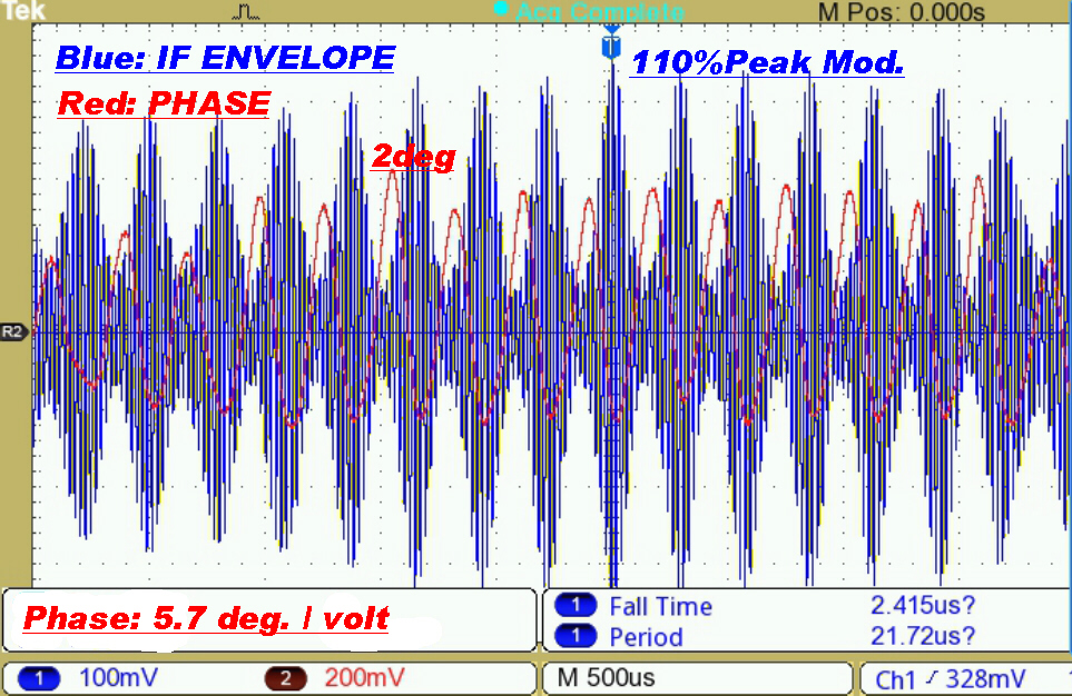
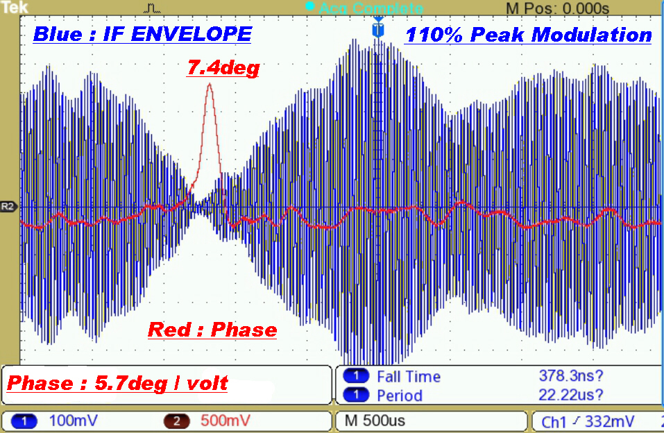
The phase modulation on two of the local AM broadcast transmitters is shown below.
Consider the expression for the phase modulation θ(t):-
θ(t) = tan-1[ Q(t)/( 1 + P(t) )]
Here P(t) the inphase and Q(t) the quadrature modulation are normalised.
With present practice P(t) → -1 on negative modulation peaks and can reach +1.2 on positive modulation peaks.
Since the denominator ( 1 + P(t) ) → 0 on negative peaks, [ Q(t)/( 1 + P(t) )] can → ∞ ,
so that, even with a small quadrature component Q(t), the phase deviation θ(t) can be large.
Test Results on 4QG 792KHz(RN)
This is a 20KW transmitter on 792KHz diplexed with a 50KW transmitter on 612KHz.
The radiator is the 650 foot monopole with capacitive hat shown above.
Both transmitters are solid state.
The transmission path is about 32KM over a built up area.
The receiving antenna is a non-resonant loop.
The receiver is operated with its maximum bandwidth of 36KHz.
|
|
|
The transmitter is modulated fairly heavily at about 1.8KHz, yet the phase deviation
is below 2 degrees. |
This illustrates the expected phase modulation transient on a negative modulation peak. |
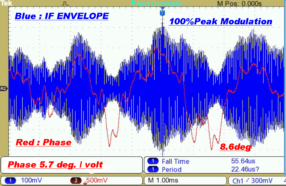
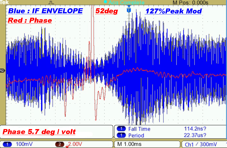
Test Results on a Commercial Transmitter
Distortion was noticeable on an envelope detector and even worse with a product demodulator.
The audience for which the "music" was intended would probably regard the distortion as a bonus.
|
|
|
A phase deviation of 8.6 degrees on a signal modulated at 330Hz can only be explained by non-linear effects in the transmitter. |
Here the transmitter is modulated very heavily. |
 The new 4QR transmitter employed low level plate modulation followed
by two class B linear amplifiers.
Apart from an increase in power from 5KW to 10 KW, the performance was inferior
to the transmitter it replaced.
The distortion was high - mainly due to the misapplication of feedback.
A batch of SS1971 output tubes with high secondary grid emission increased
the distortion still further.
The transmitter shared program with a 1KW FM transmitter, so a direct comparison
of distortion caused a redesign. This resulted in a highly competitive performance
of the AM transmission.
Surprisingly, the vacuum tube complement was older than in the previous transmitter.
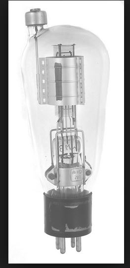
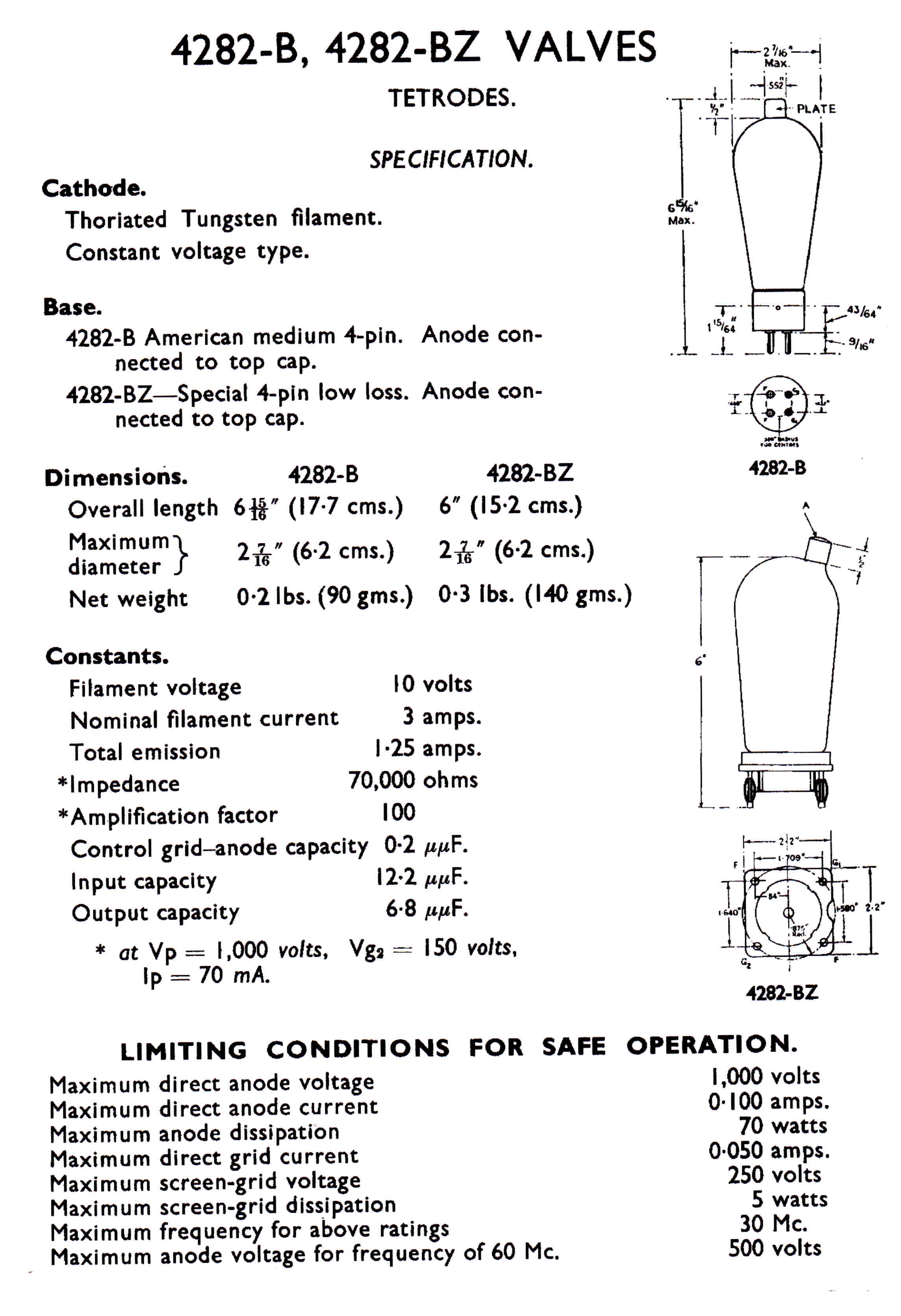
The structure of the 4282 tetrode is shown on the right.
The 4QR Tube Lineup:-
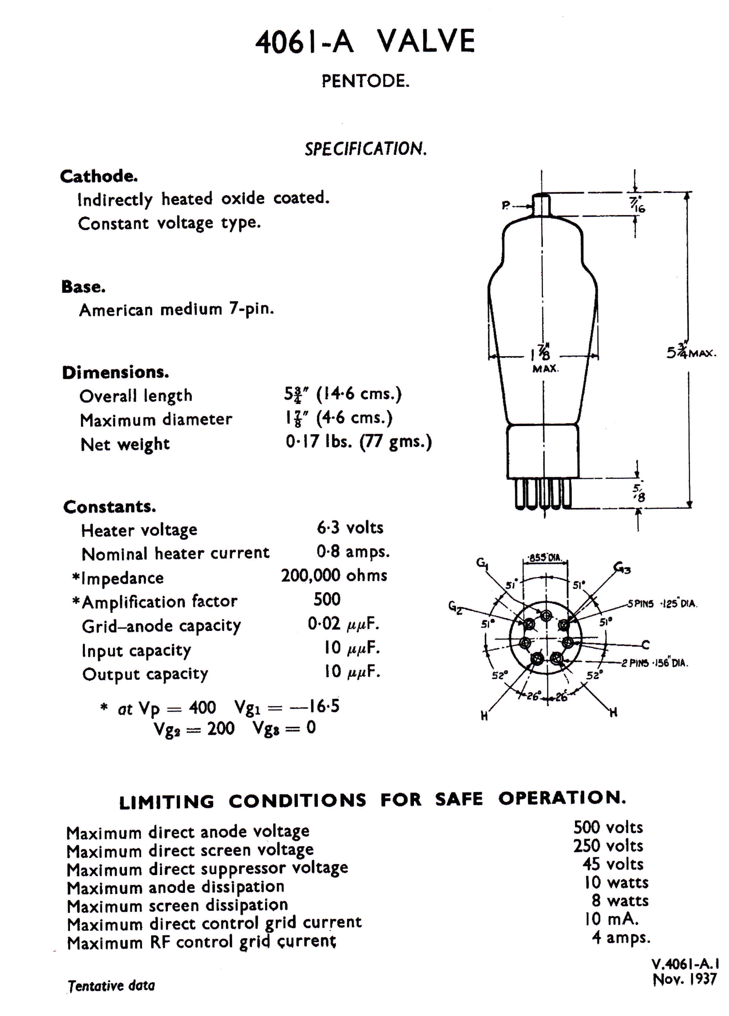
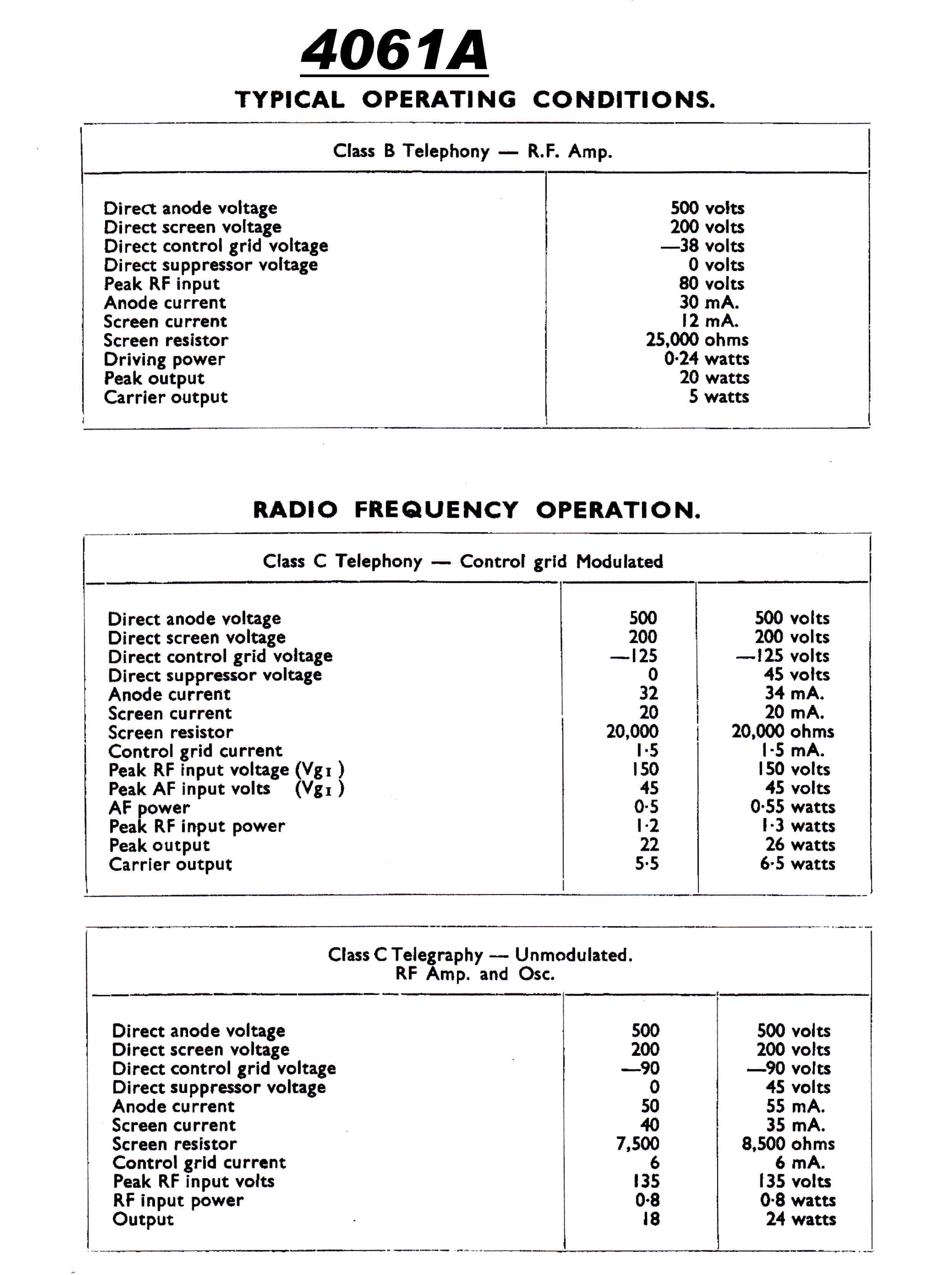
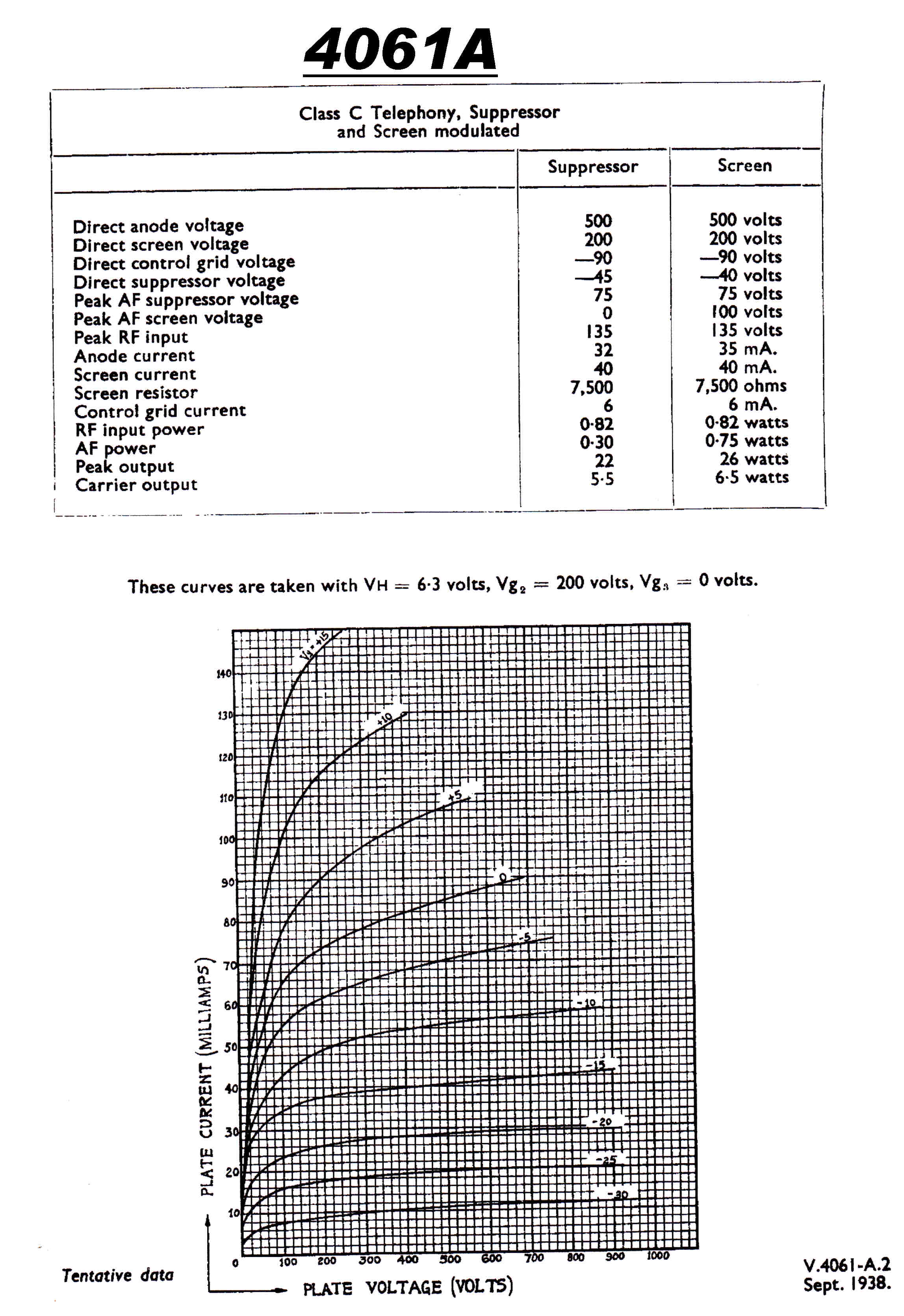
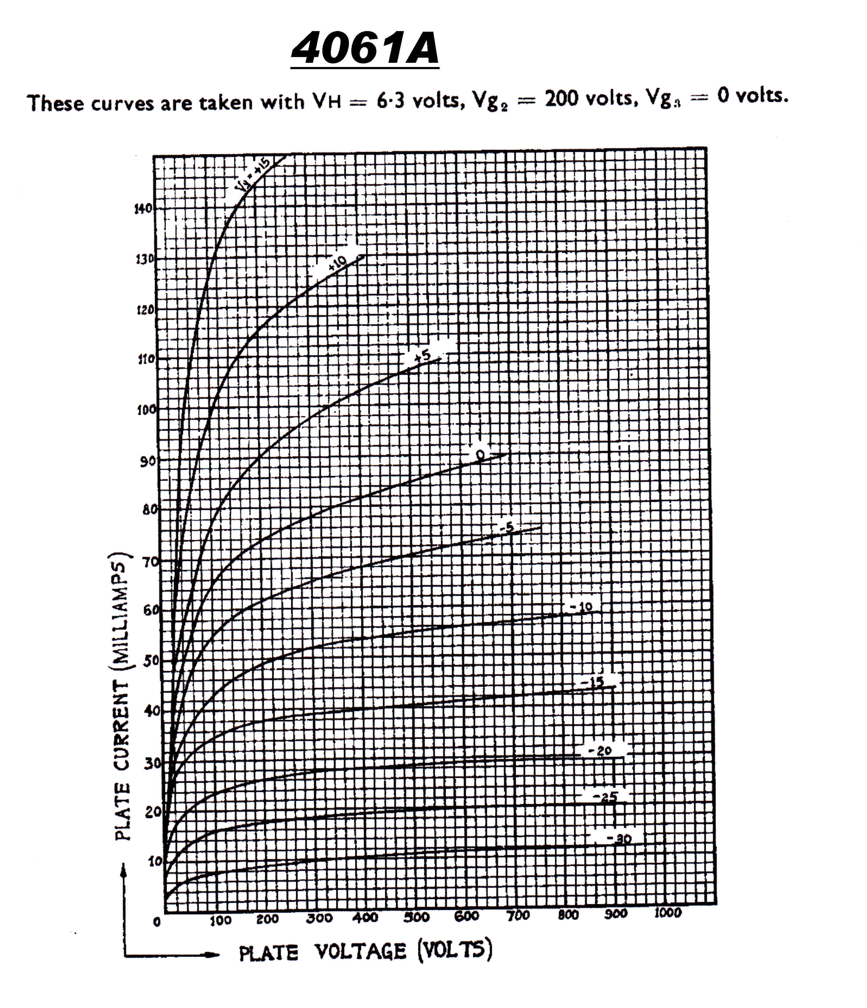
4061 Indirectly heated Pentode low level audio and RF
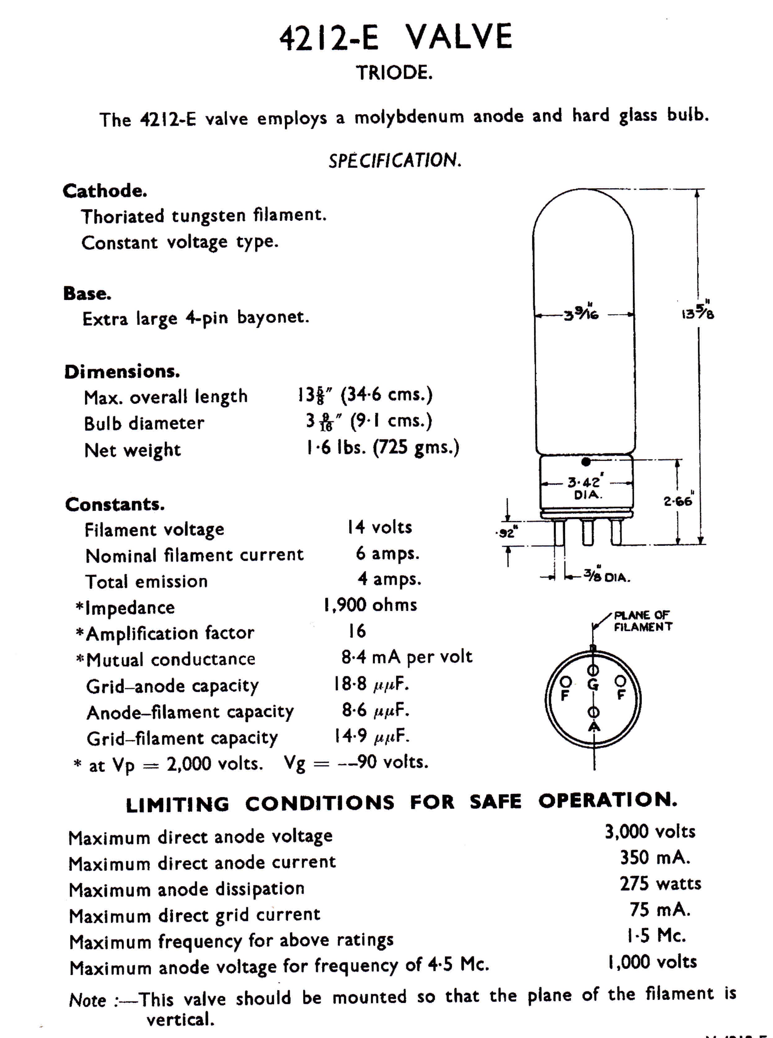
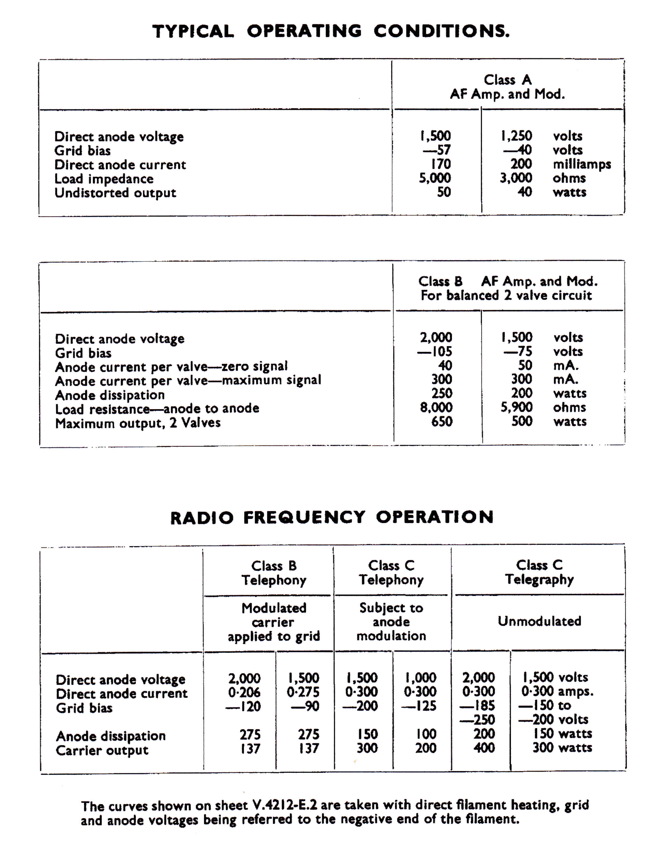
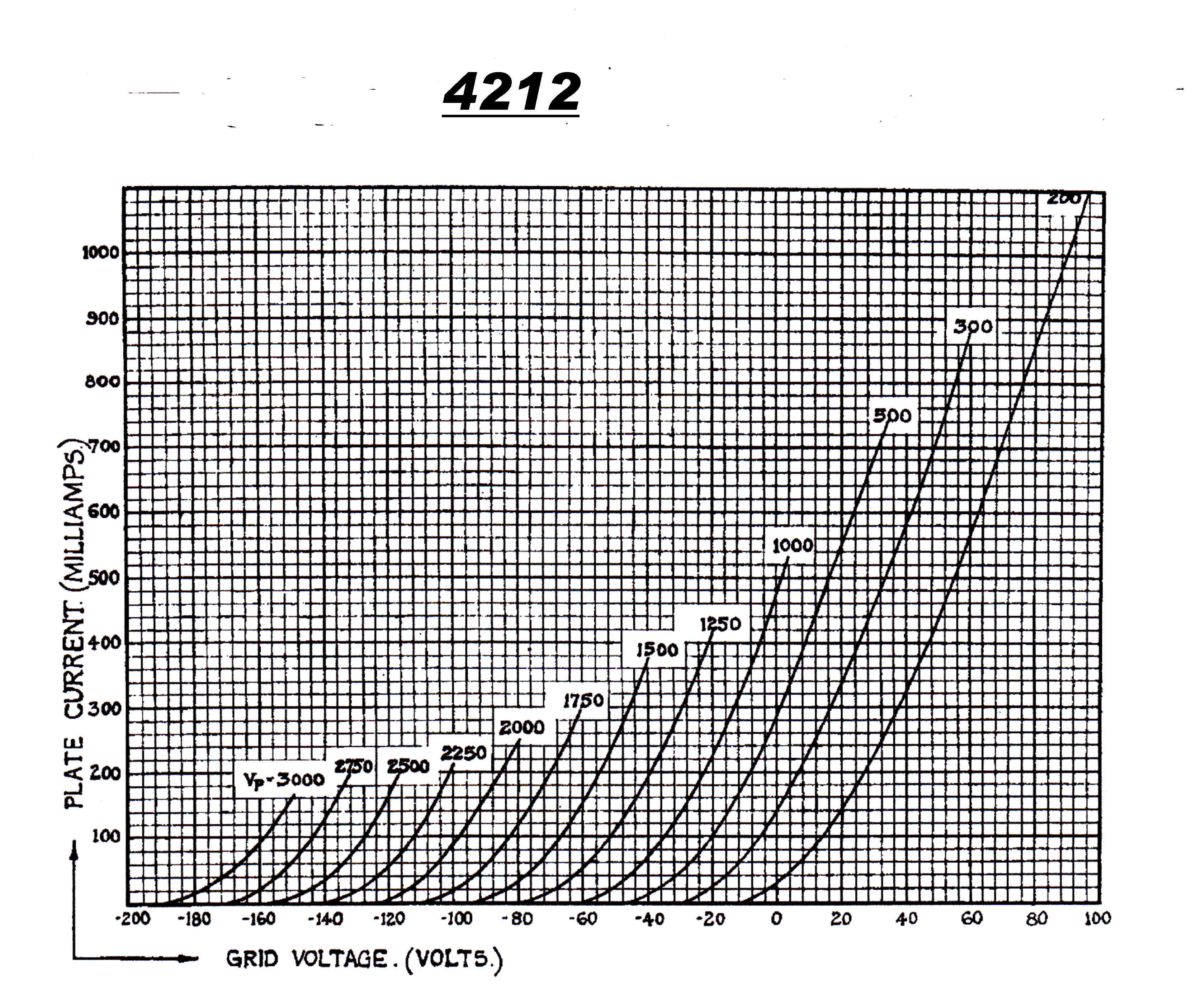
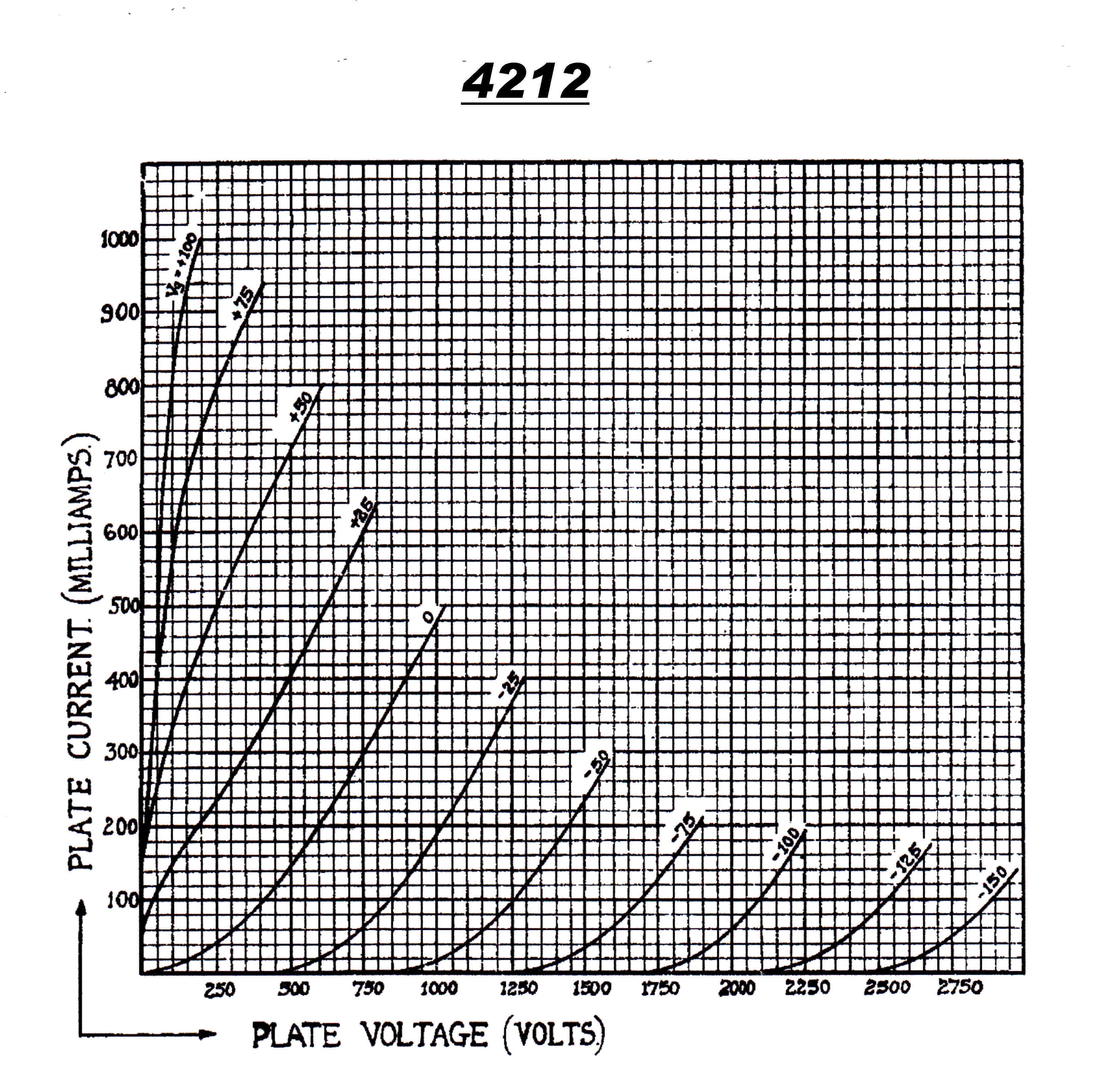
4212 Triode class A modulator stage
4282 Tetrode overdriven plate modulated stage
4279 Air-cooled first class B linear amplifier
SS1971 Final class B output amplifier. Two water cooled tubes in parallel.
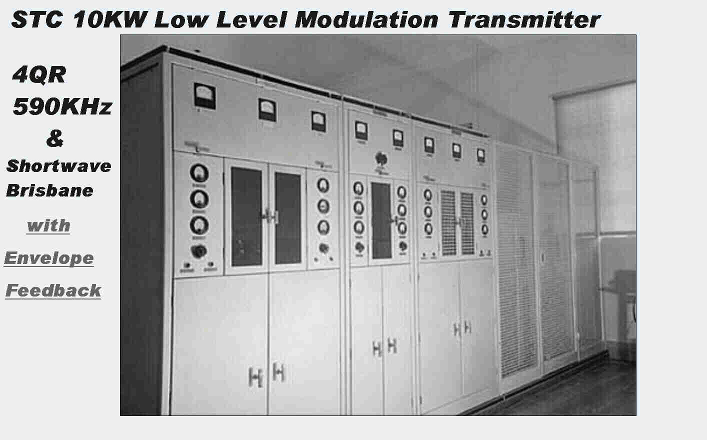
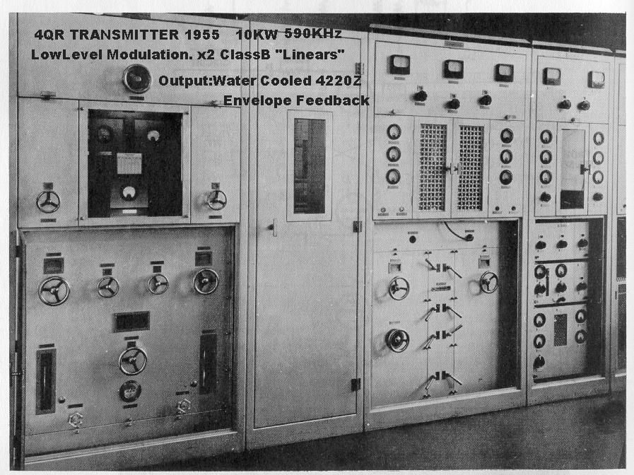
The low frequency version, 4QR, and the high frequency version, VLM,
of the transmitter are shown below.
|
|
|
The heat exchanger for the water cooled tubes was situated behind the transmitter. |
I think that this is the high frequency mirror image VLM . |
This transmitter was the last to use old fashioned tubes.
Their characteristics are given below.
4061 Low Level Audio and RF
|
|
|
|
|
|
|
4212 Class A Triode Modulator
|
|
|
|
|
|
|
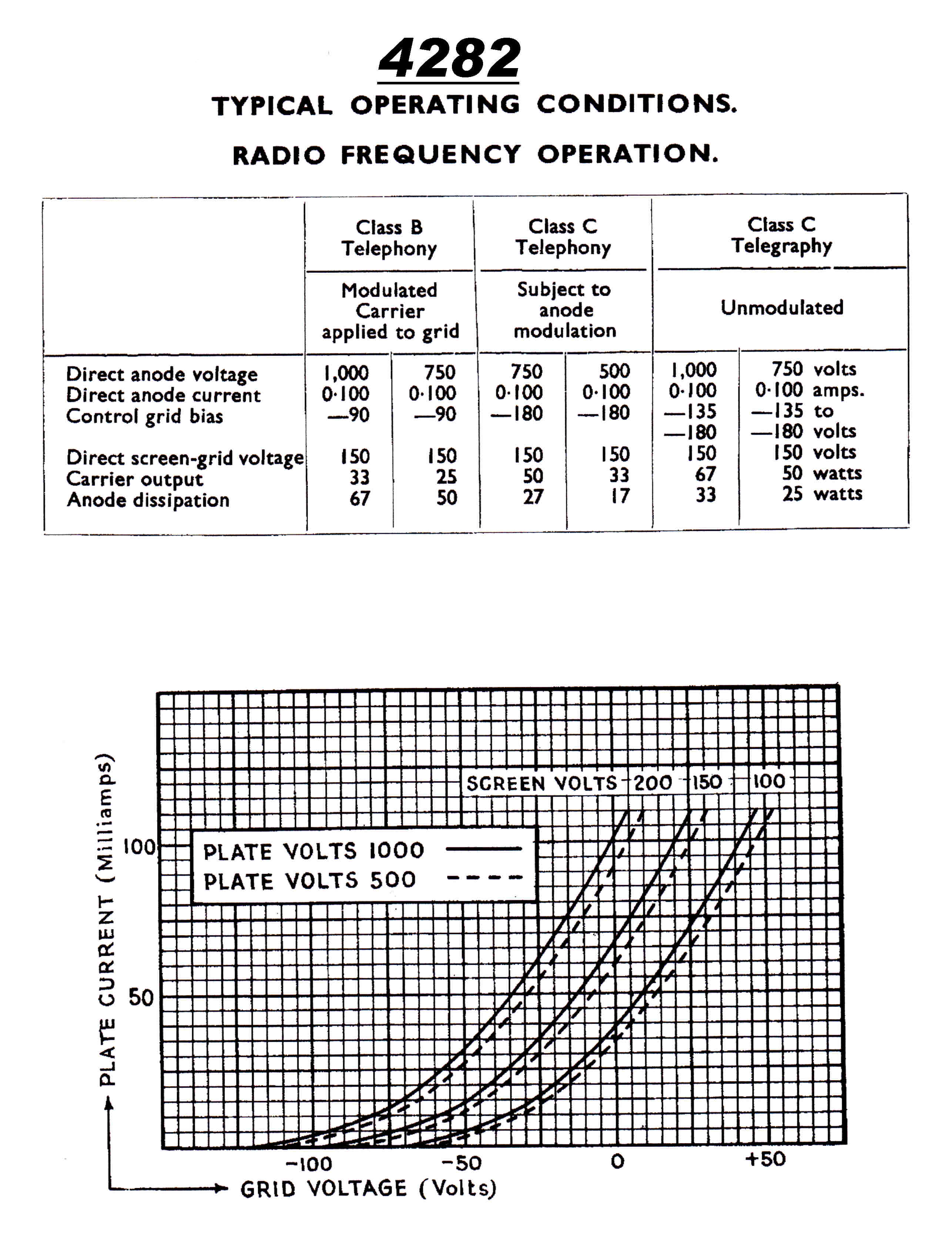
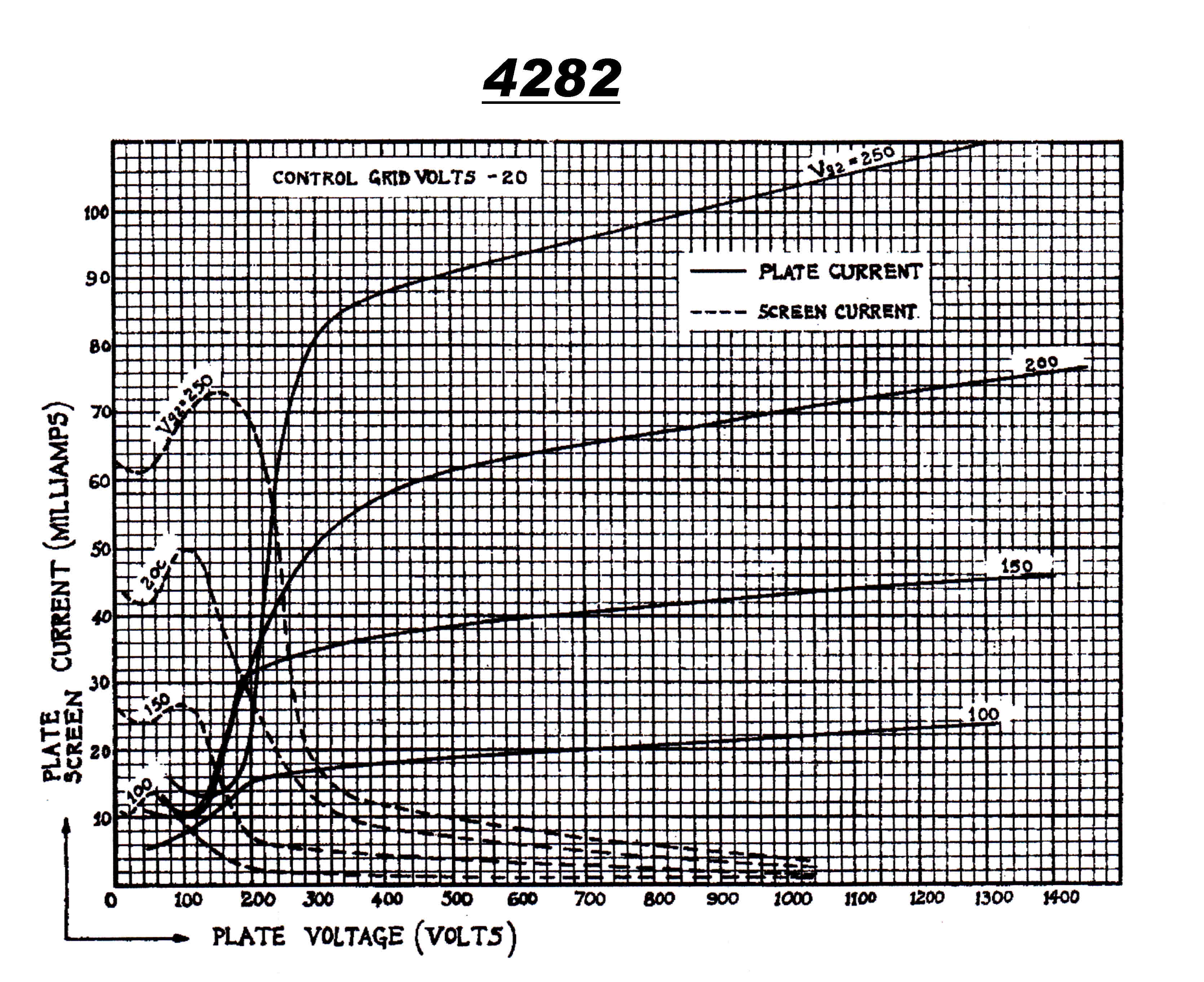
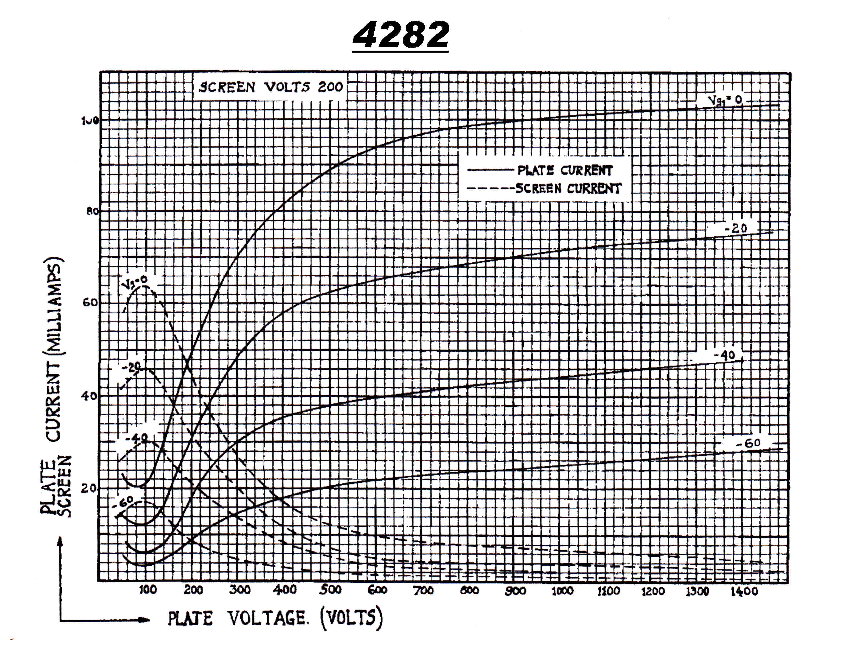
4282 Tetrode Plate [Screen] Modulated Stage
|
|
|
|
|
|
|
4279 Triode - First Class B Linear

|

|

|

|
|
|
|
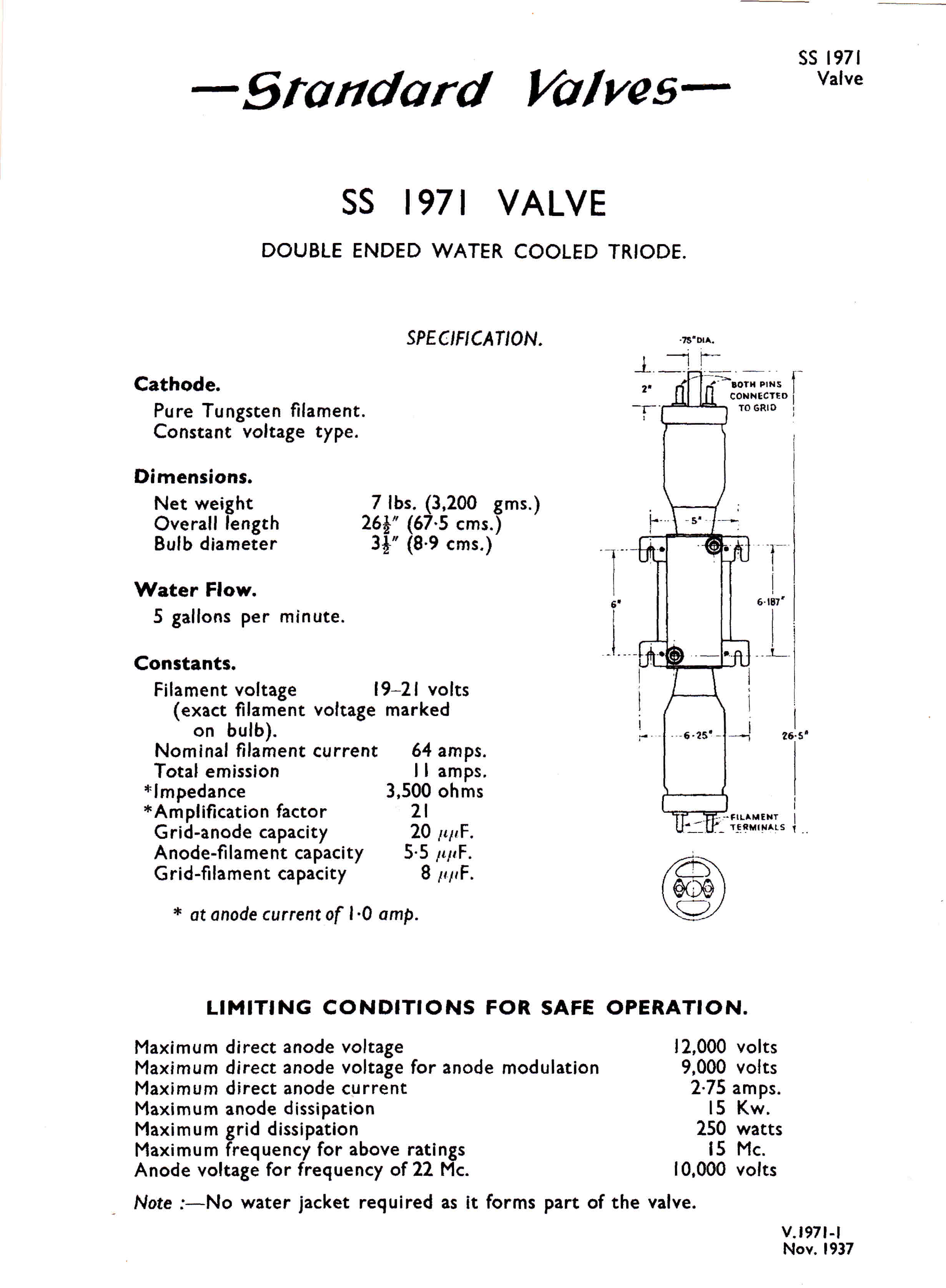
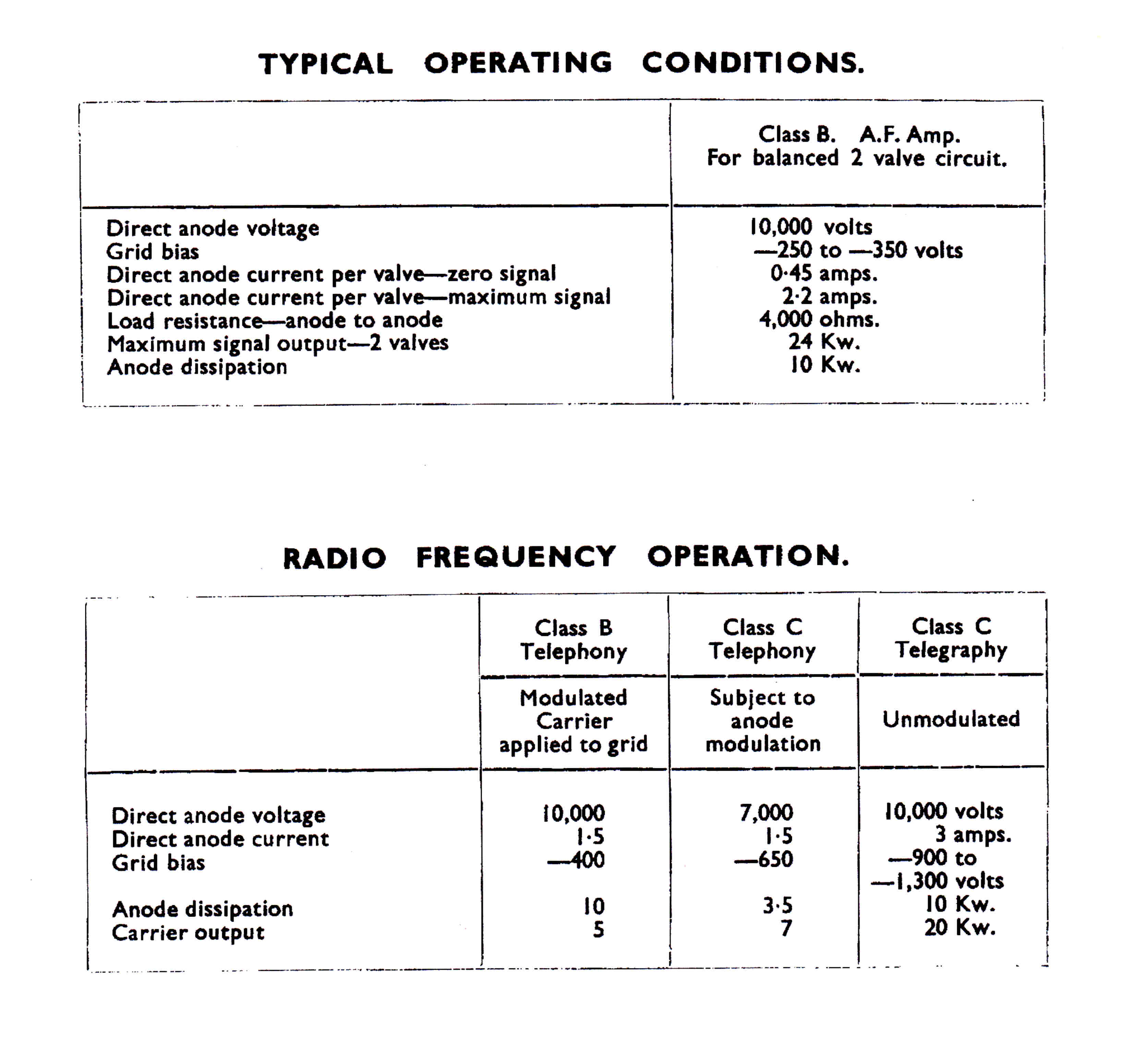
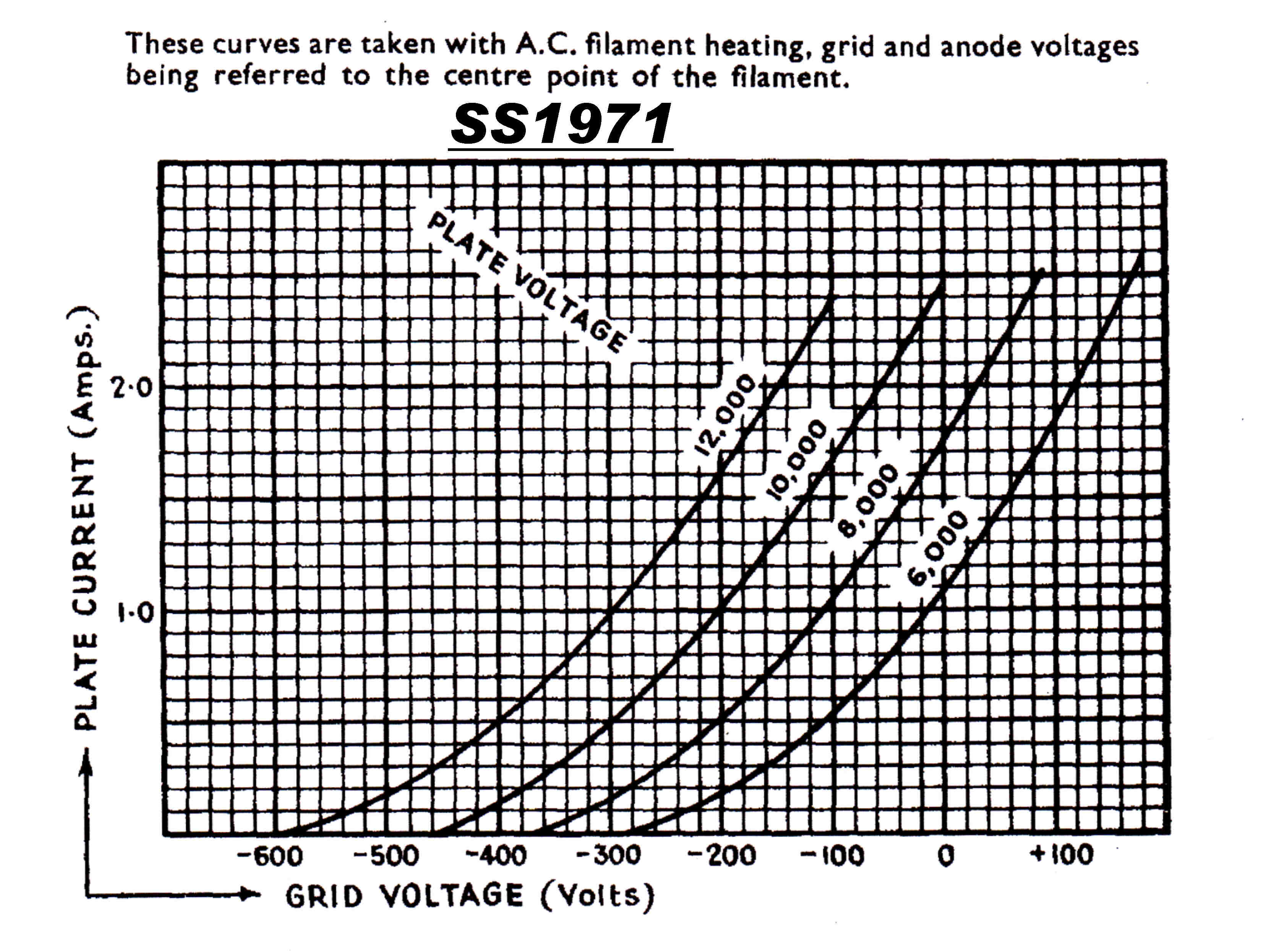
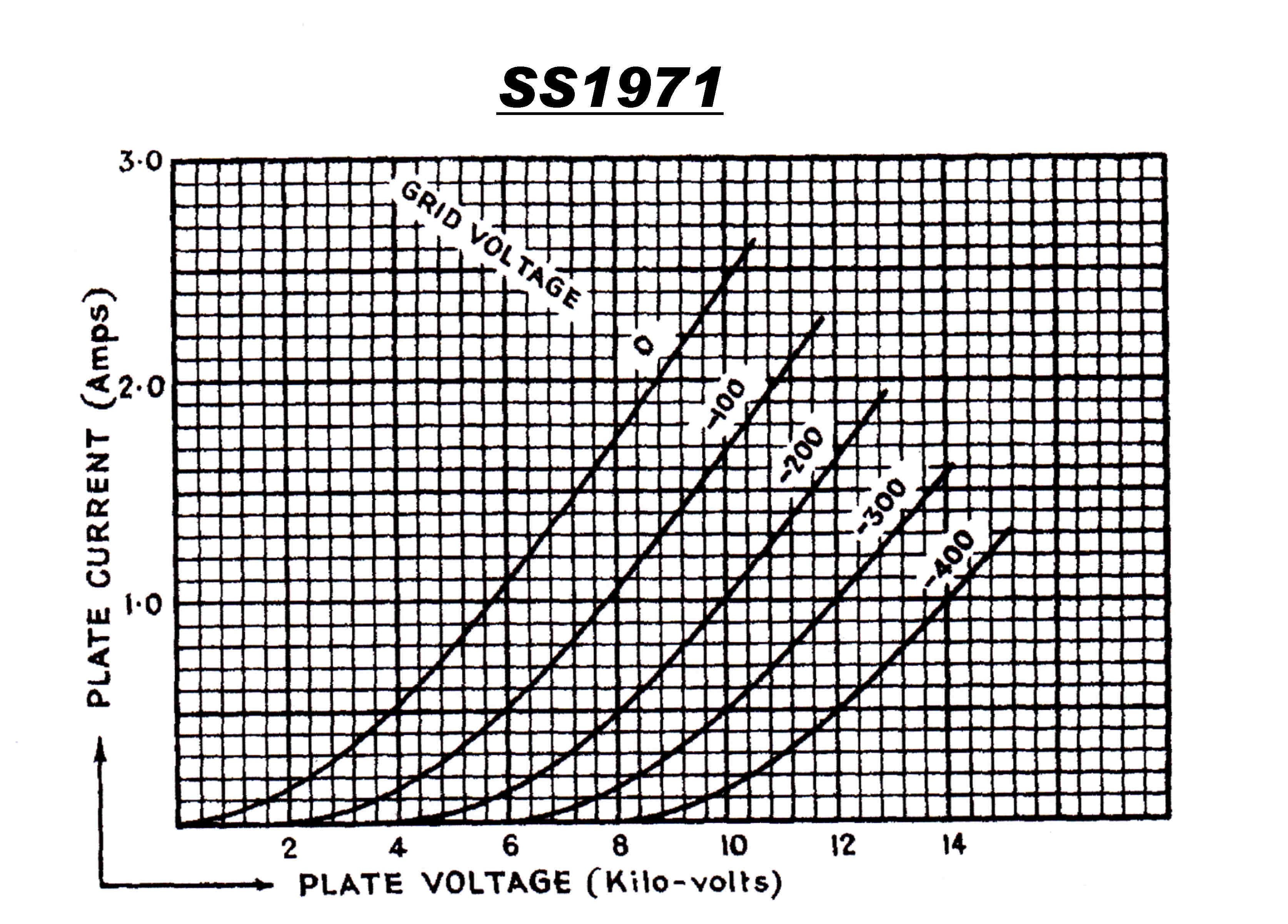
SS1971 Water cooled triodes - Two in Parallel
Class B Linear Output Stage
|
|
|
|
|
|
|
The class B inear output stage of the 4QR transmitter employed two SS1971 triodes
in parallel.
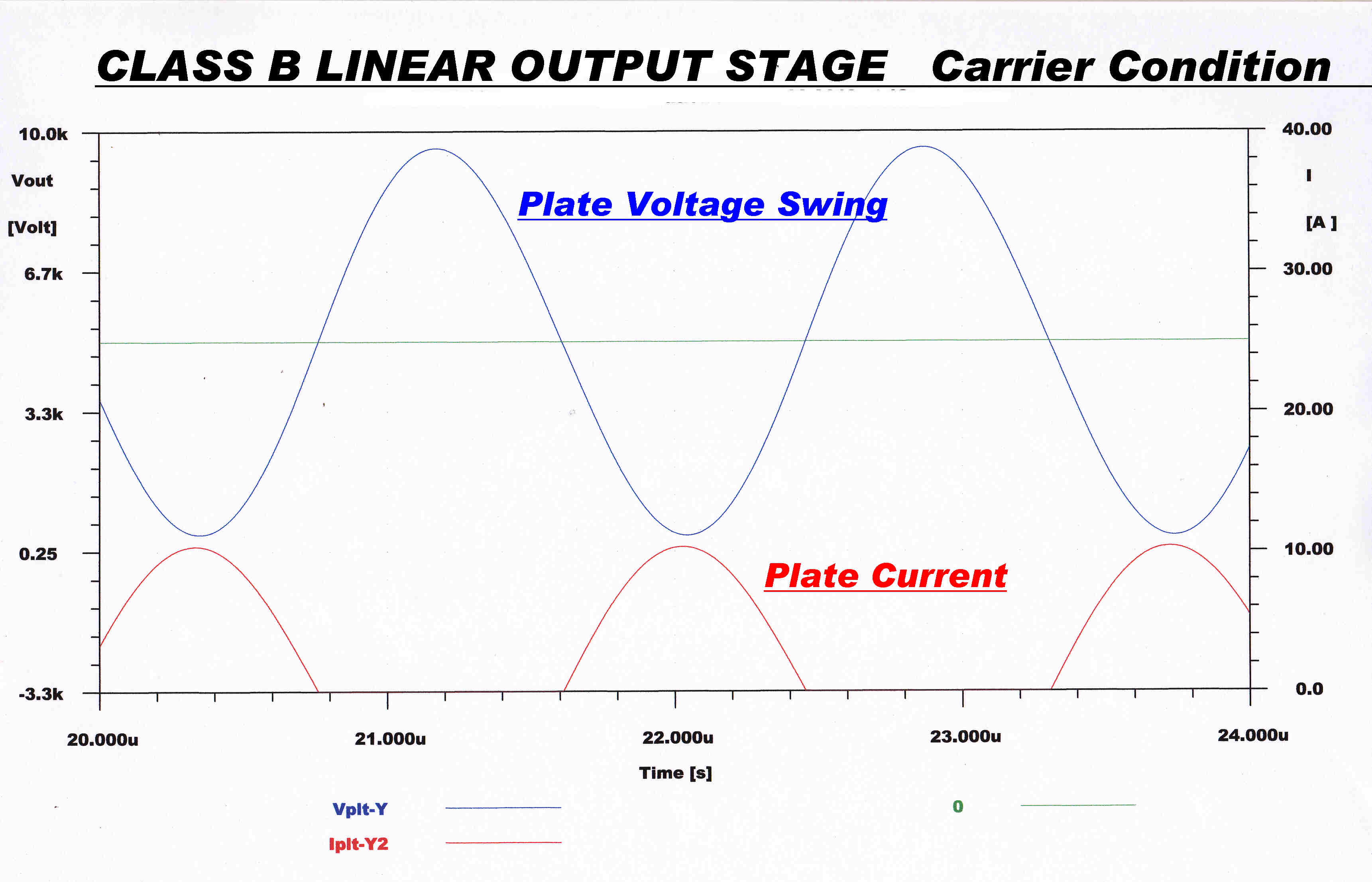
From the data sheet the carrier conditions for a 10KW output are:-
Vb = 10 KV : DC plate voltage
Pcar = !0KW : carrier power
Idc = 3 A : DC plate current
Pin = 30KW : total input power independent of modulation
Efficiency (ηcar) at carrier = 30%
Pmod = 15KW : Power output at full modulation 15KW
Efficiency (ηmod) at full modulation = 50%
We can now design the output stage:-
The plate current conduction angle is 180 degrees so:-
Ip = Π Idc = 3xΠ = 9.425A
where Ip is the peak plate current
Iprf = (Π/2 )Idc = 3 x (Π/2) = 4.712A
where Iprf is the peak fundamental plate current
Now the power output is given by:-
Pcar = [1/2][Iprf]2 Rl
where Rl is the resistive load at carrier frequency
∴ Rl = 2 Pcar / [Iprf]2
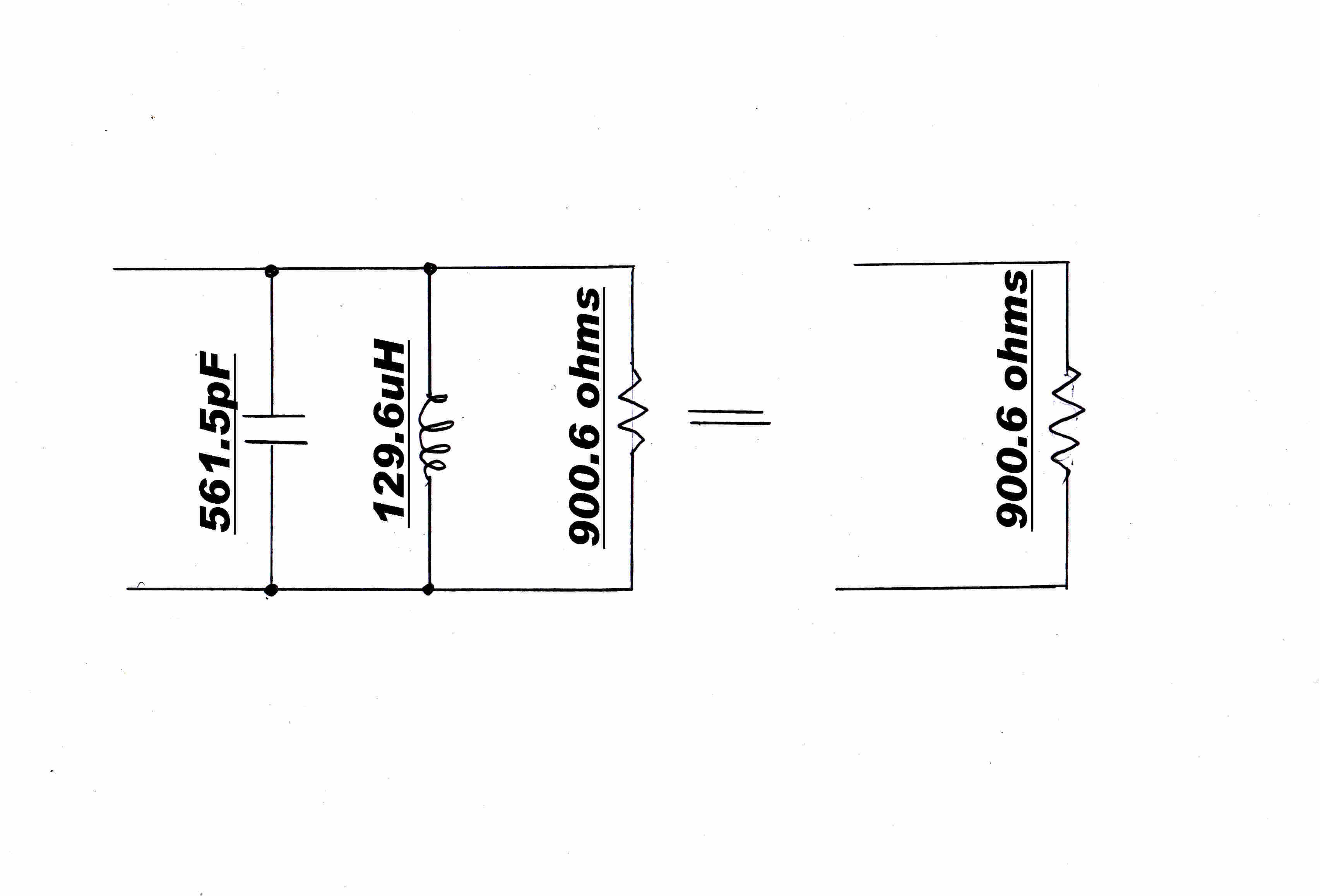
∴ Rl = 2 x 10⁴ / (4.712)2 = 900.6 ohms
L and C of Tank Circuit in Plate of Final Stage
The tank circuit must be tuned to the carrier frequency, fc, 590KHz.
The loaded Q and hence the L/C ratio is a compromise.
(1) The loaded Q, QL, must be high enough to ensure the plate voltage waveform
is substantially sinusoidal.
(2) The loaded Q, QL, must be low enough to pass the highest modulating frequencies.
If envelope feedback is used the pass band outside the audio range
will also be of interest.
Experience shows that a loaded Q of about 10 is about right.
The reactance of the tank L and C should then be 900.6/10 = 90.06 ohms
At a carrier frequncy, fc, of 590KHz this gives :-
LT = 24.295 x 10⁻⁶H
CT = 2.995 x 10⁻⁹F
The loaded Q is less than 10, since the plate current of the triode output tube
varies with plate voltage and so has an effective output resistance.
This is in parallel with the load resistance and so lowers the Q.
Design of the Matching Network
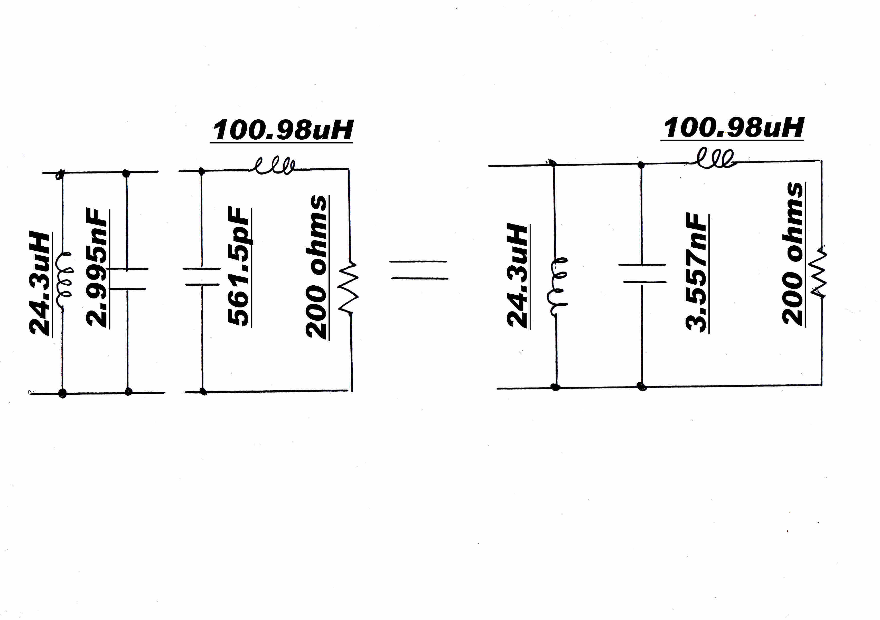
The transmitter is to match into a 200 ohm open wire line.
The 200 ohm load can be transformed into a 900.6 ohm parallel load by adding a series inducto Ls.
The Q of the series load Qs is given by:-
Qs = [ R1/R2 - 1 ]1/2
Qs = [ 900.6/200 - 1 ]1/2 = 1.8717
R// = [ 1 + Q2 ] Rs = [ 1 + 1.87172 ] 200 = 4.503 x 200 = 900.6 As required.
The series resctance Xs is given by:- Xs = Qs Rs = 1.8717 x 200 = 374.33 0hms
Ls = Xs/( 2 Π fc ) = 374.33/( 2 x 3.1416 x 590000 ) = 100.98 uH
The equivalent parallel inductance L// is given by:-
L// = Ls[ 1 + 1/Q22 ] = 1.285 x 100.98 = 129.8 uH
The parallel capacity to cancel the parallel reactance ( 481.18 0hms) is given by:-
C// = 1/( 2 Π fc Xs ) = 1/( 2 x 3.1416 x 590000 x 481.18 ) = 56.06pF
The design steps to synthesise the output network are shown below.

|
|
|
|
A series inductor Ls is added to produce an equivalent parallel resistance equal to
the required input resistance. |
The positive reactance of the parallel inductance is then cancelled by placing
a negative reactance of the same magnitude in parallel. |
The approximate Q of the final tank circuit is chosen. |
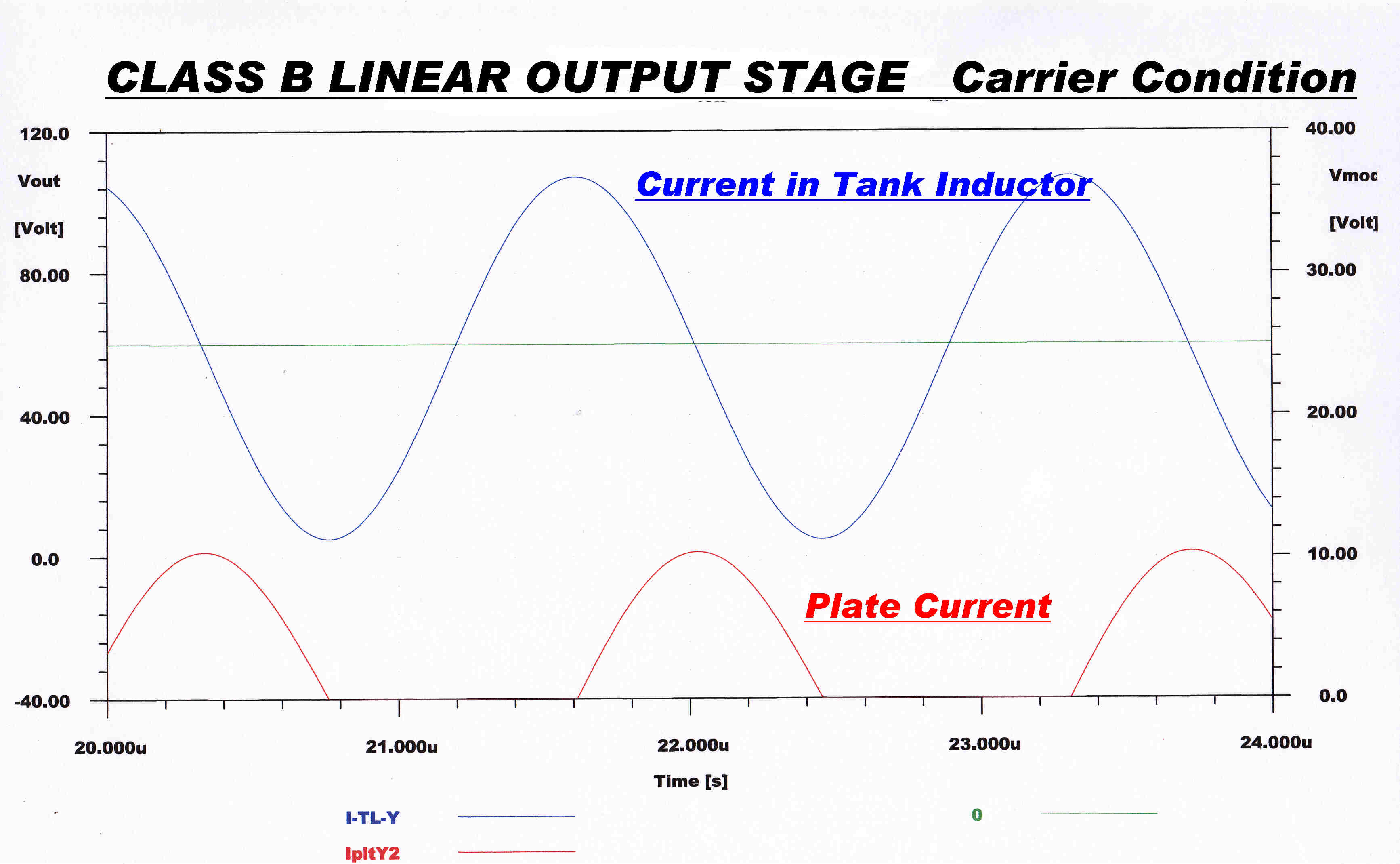
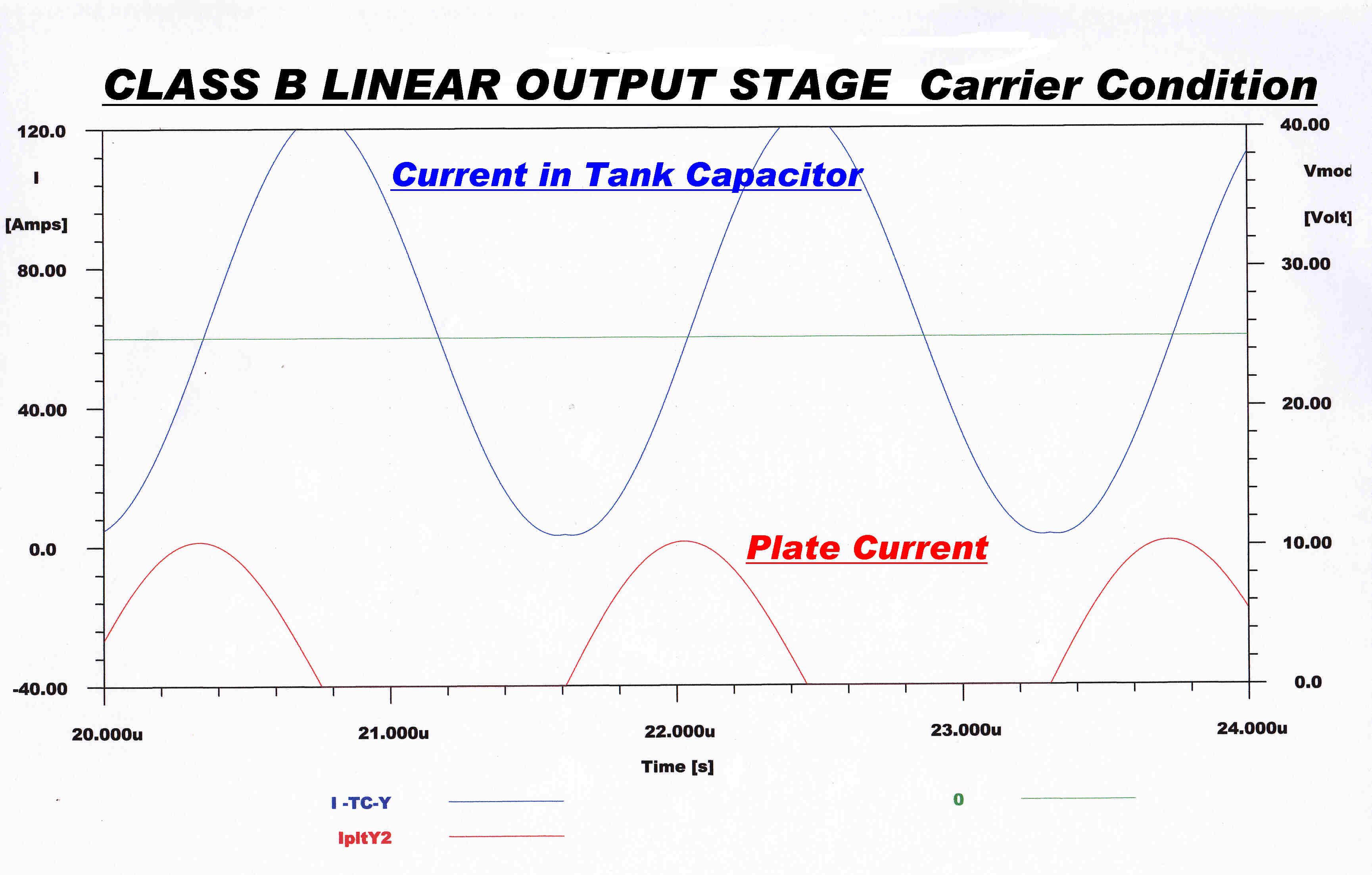
Key Waveforms in the Tank Circuit are shown below:-
|
|
|
|
The plate voltage waveform is a good approximation to a sinusoid -
indicating that the loaded Q is high enough. |
The current in an inductor lags the voltage by 90 degrees. |
The current in an capacitor leads the voltage by 90 degrees. |
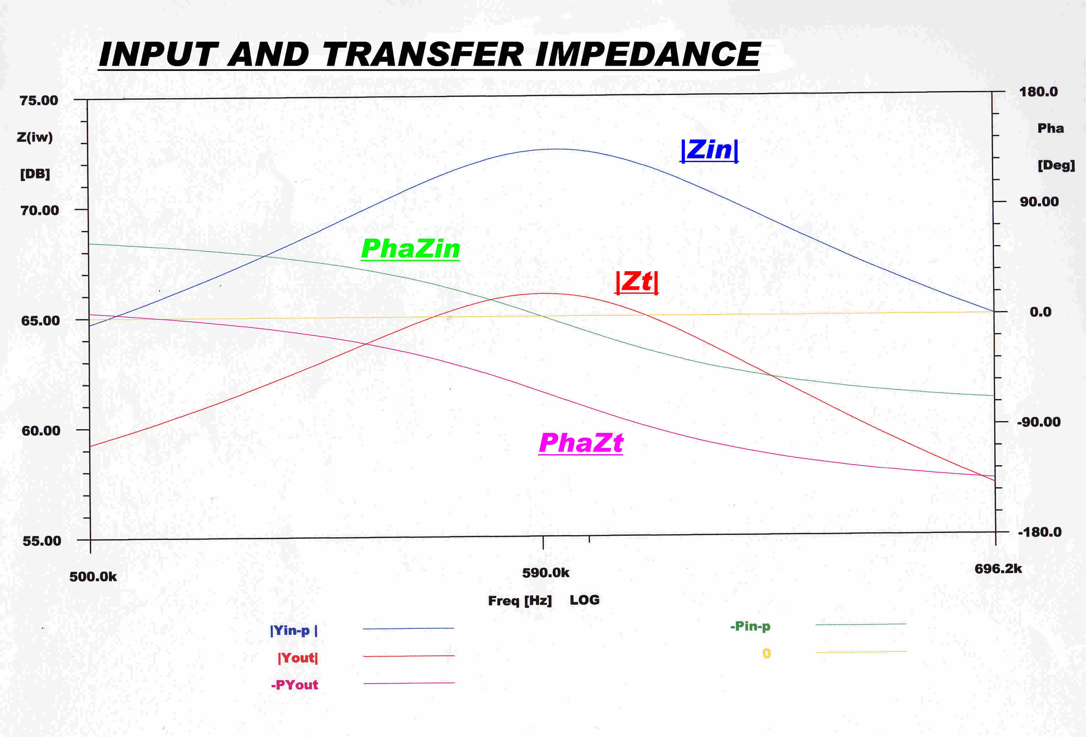
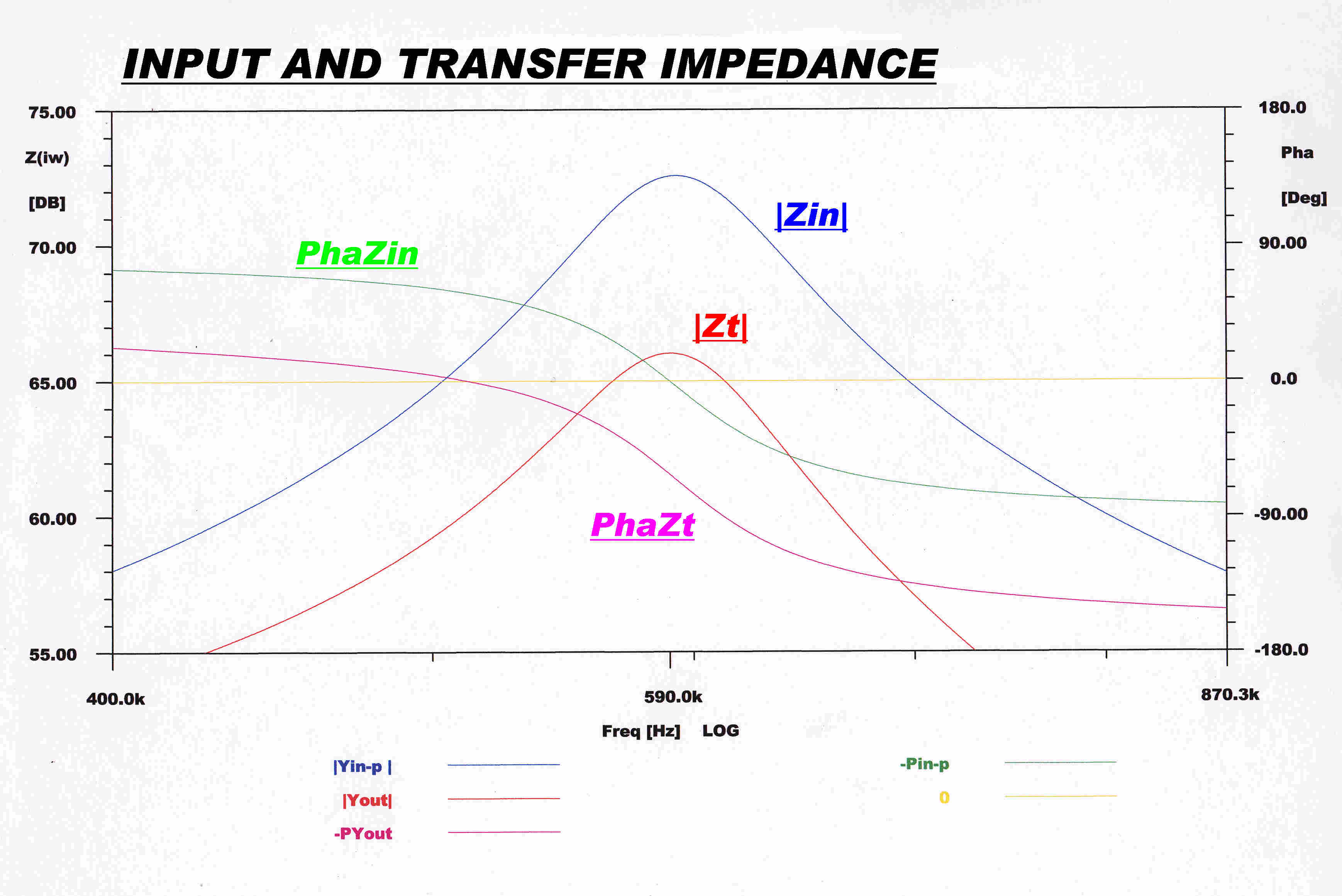
The input impedance and the transfer impedance
of the matching network is shown below:-
|
|
|
The input impedance and the transfer impedance of the matching network. |
The same curves as opposite but over a greater frequency range. |
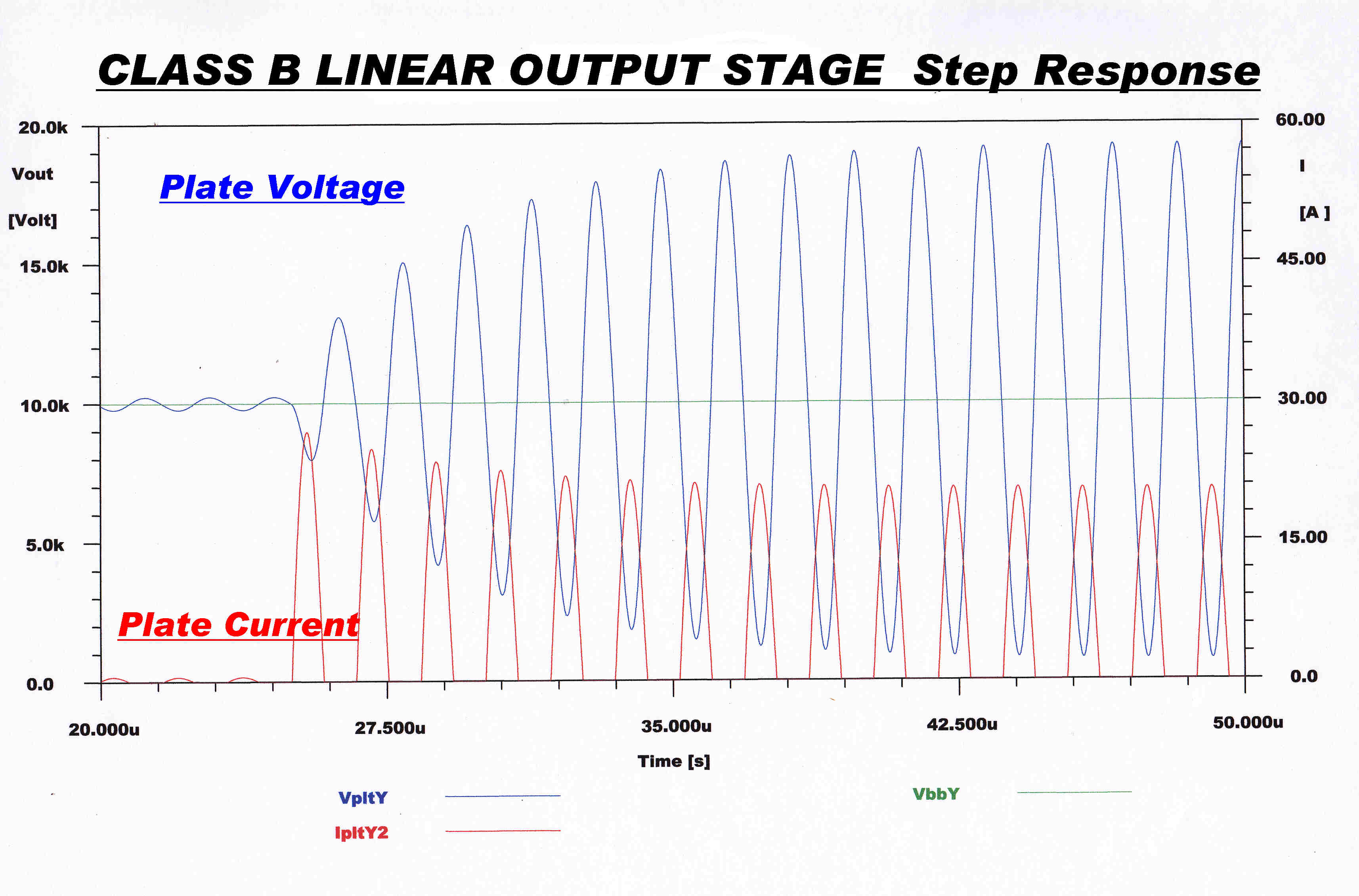 The step function response of the plate voltage of the class B
linear output stage is shown opposite.
The magnitude of the plate current pulse is affected by the
the plate voltage in the triode output stage and this lowers
the response time.
There are two ways of looking at this:-
[1] The two triodes have a relatively low plate resistance
( ≈ 1200 ohms )
This is in parallel with the load resistance 900.6 ohms.
The loaded Q, QLd is given by:-
QLd = (R//) / (ωL), so that R//
is decreased by the paralleled plate resistance and with it
the loaded QLd.
This increases the bandwidth and lowers the response time.
The modulation bandwidth BM is given by:-
BM = ωc / ( 2 QLd )
[2] There is another way to explain the mechanism of rise time
reduction by the triode output tubes.
The impedance ZM(p) seen by the triode plates for the modulation
envelope can be approximated by:-
ZM(p) ≈ RLd / ( 1 + τ p )
where τ is the time constant of the exponential type rise in
the plate voltage envelope Vplt(t) where:-
Vplt(t) = [ 1 - et/τ ]
The lag in plate voltage buldup causes the height of the plate current
pulses to vary acording to the transfer function:-
Y(p) ≈ ( 1 + τ p ) / ( 1 + τ1 p )
where τ1 < τ
The overall transfer function Yo(p) is then given by:-
Yo(p) = Y(p) ZM(p) =
[( 1 + τ p ) / ( 1 + τ1 p )][ RLd / ( 1 + τ p ) ]
= RLd / ( 1 + τ1 p )
This indicates a lower rise time since τ1 < τ
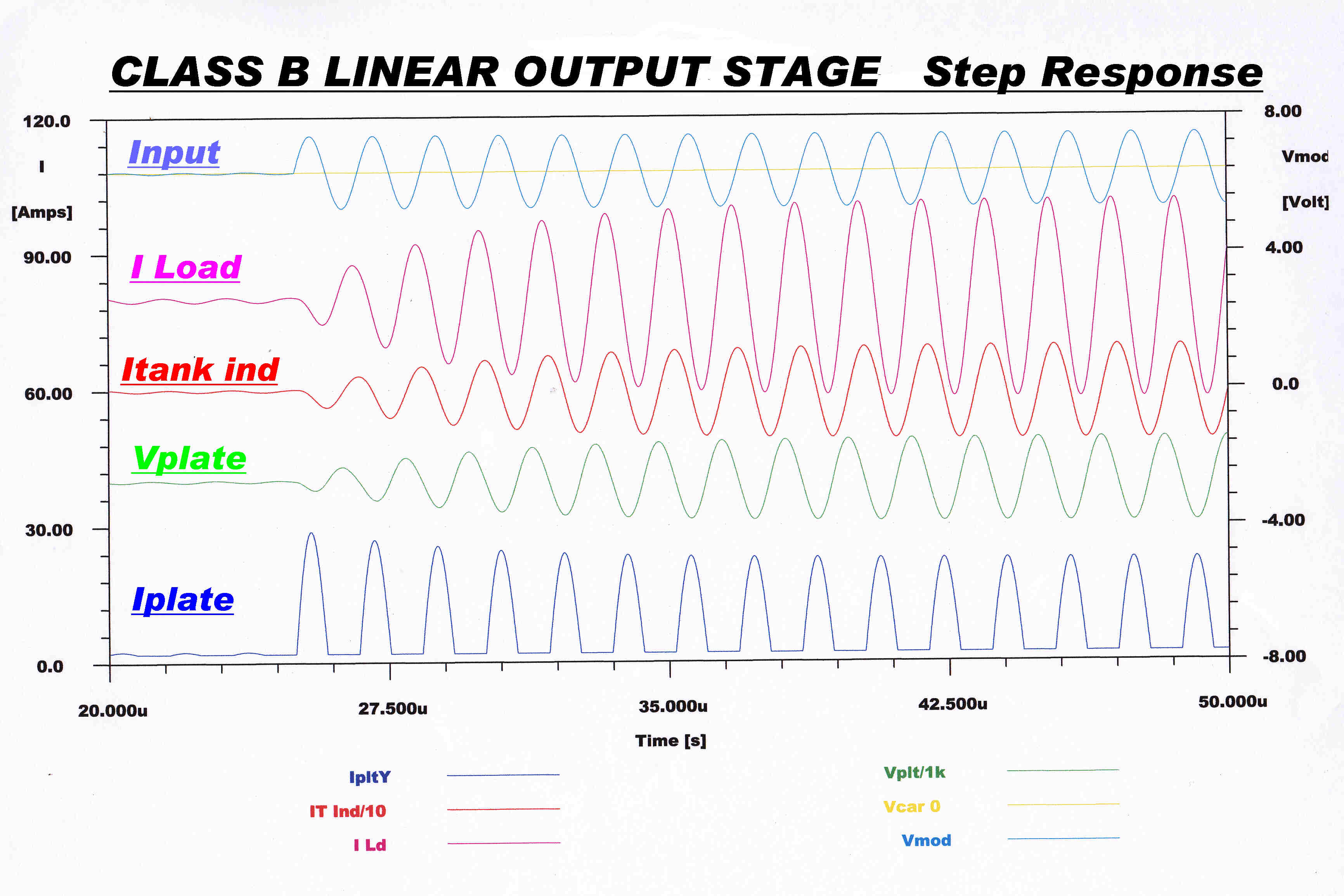 The step function response of the key variables in the class B
stage and matching network are shown opposite.
The step takes the carrier from 5% tto 200% - full modulation.
In 1956 I was in a position to encourage electrical engineering students
to design and build low distortion high bandwidth AM and FM tuners.
The 4QR signal exhibited audible distortion - an intolerable state of affairs.
A study of the 4QR transmitter circuit disclosed the miss-application of feedback.
Overall current feedback from the cathode of the final stage was applied to the
transmitter and this resulted in increased distortion rather than a reduction.
In the 4QR transmitter overall feedback was taken from a 1 ohm resistor in the
cathode of the final stage. This violated the first rule given above in two ways:-
[A] The cathode current consists of the sum of the plate and ( highly non-linear)
grid current. The required signal is derived fom the plate current.
[B] The radiated signal is derived from the fundamental component of the plate
current pulse and the feedback signal is derived from the average of the
plate current pulse. The two have a non-linear relationship, so in linearising
the average current, the feedback introduces distortion in the radiated signal
which is derived from the fundamental component.
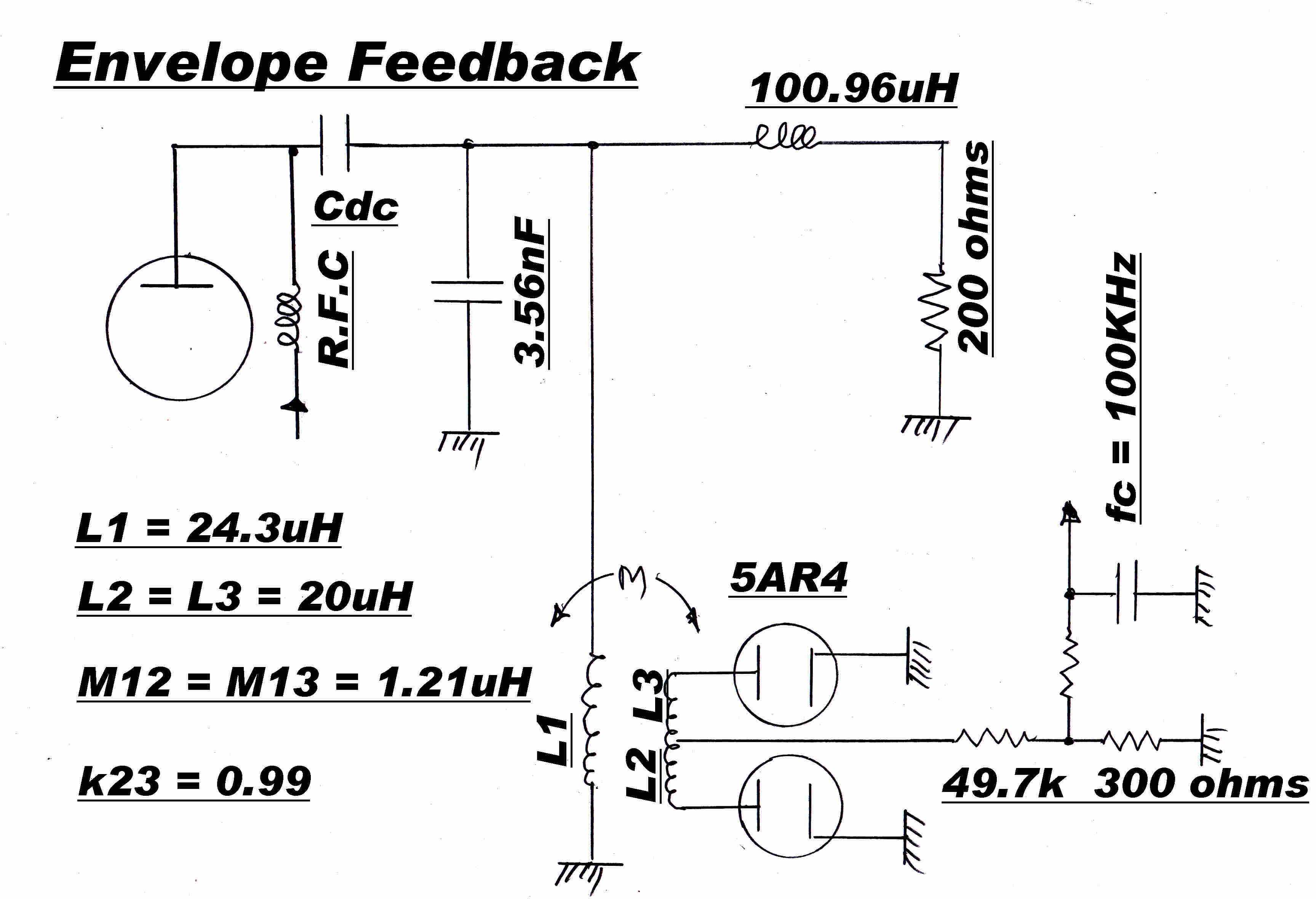
The current fedback in the final cathode was replaced by overall envelope feedback
derived from the tank circuit in the plate of the output stage.
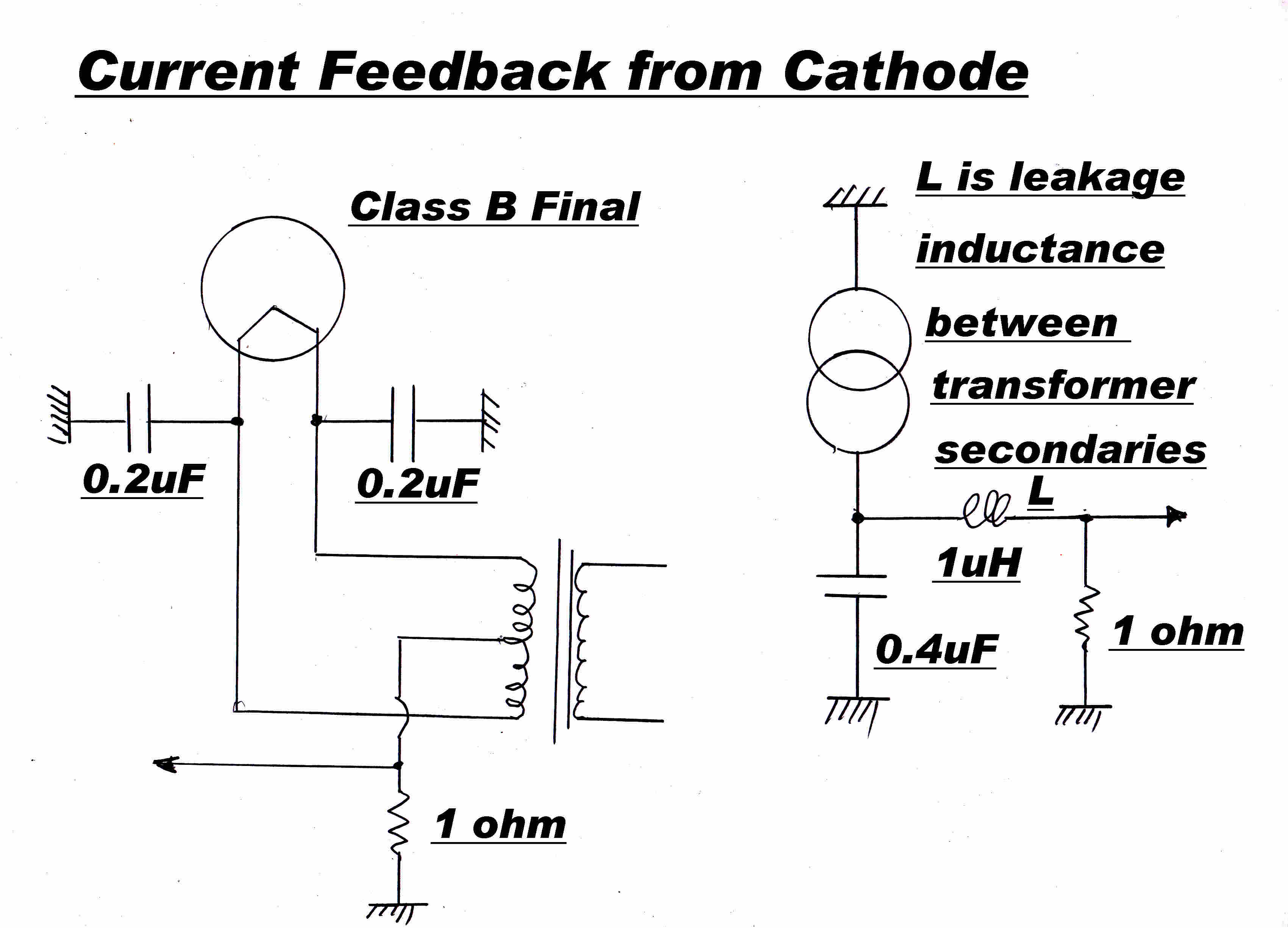
|
|
|
The average current in the class B output stage develops an audio
feedback signal across the cathode resistor. |
A small inductive pickup loop L2-L3 is placed at the earthy end of
L1 to minimise spurious electrostatic signals. Electrostatic screens
may be added to reduce the effect still further. |
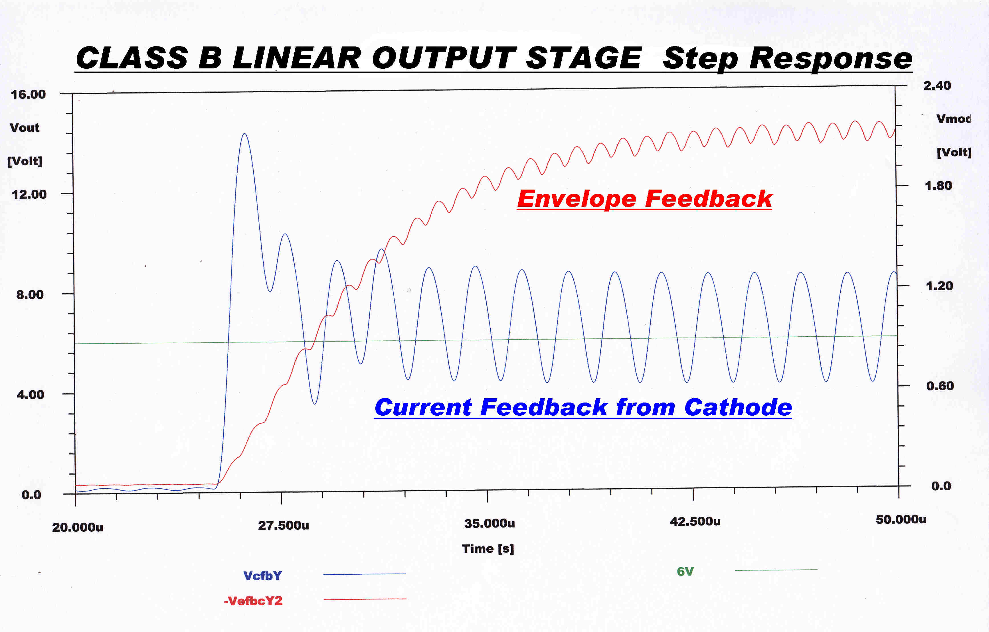 The step function responses of the feedback circuits described
above are shown opposite.
The response is calculated for an initial input on the grid of the output
stage of 5% of carrier which then suddenly changes to 200% of carrier.
The audio transfer function of the current feedback is of the form:-
Yc(p) = ( 1 + τ1p )/( 1 + τ2p )
where τ1 > τ2
The corresponding steady state response is flat up to a frequency f1
given by f1 = 1/( 2 π τ1 ) rising by 6db/octave to a
plateau starting at f2 = 1/( 2 π τ2 )
The transfer function contributes to closed loop stability.
This transfer function is in the feedback loop, not in the forward loop, so it
will result in a depression of the closed loop high frequency response.
To summarise:-
Current feedback from the cathode of the class B linear output stage is
cheap and simple - it requires only 1 20 watt 1 ohm non- inductive resistor.
It does not introduce the dynamic stability problems associated with
envelope feedback.
It also increases the overall distortion.
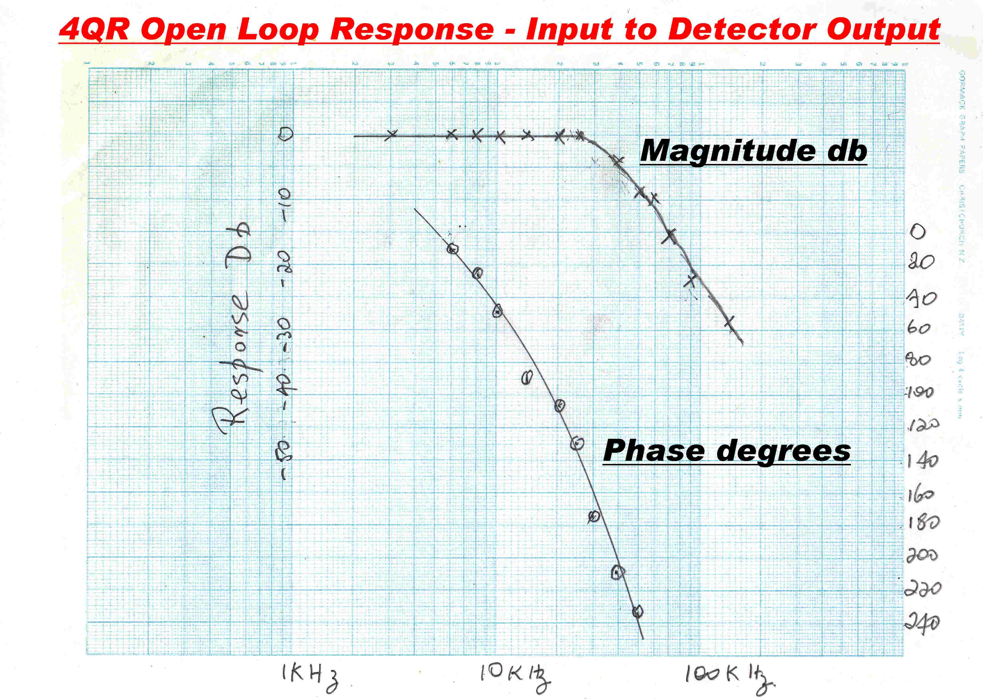
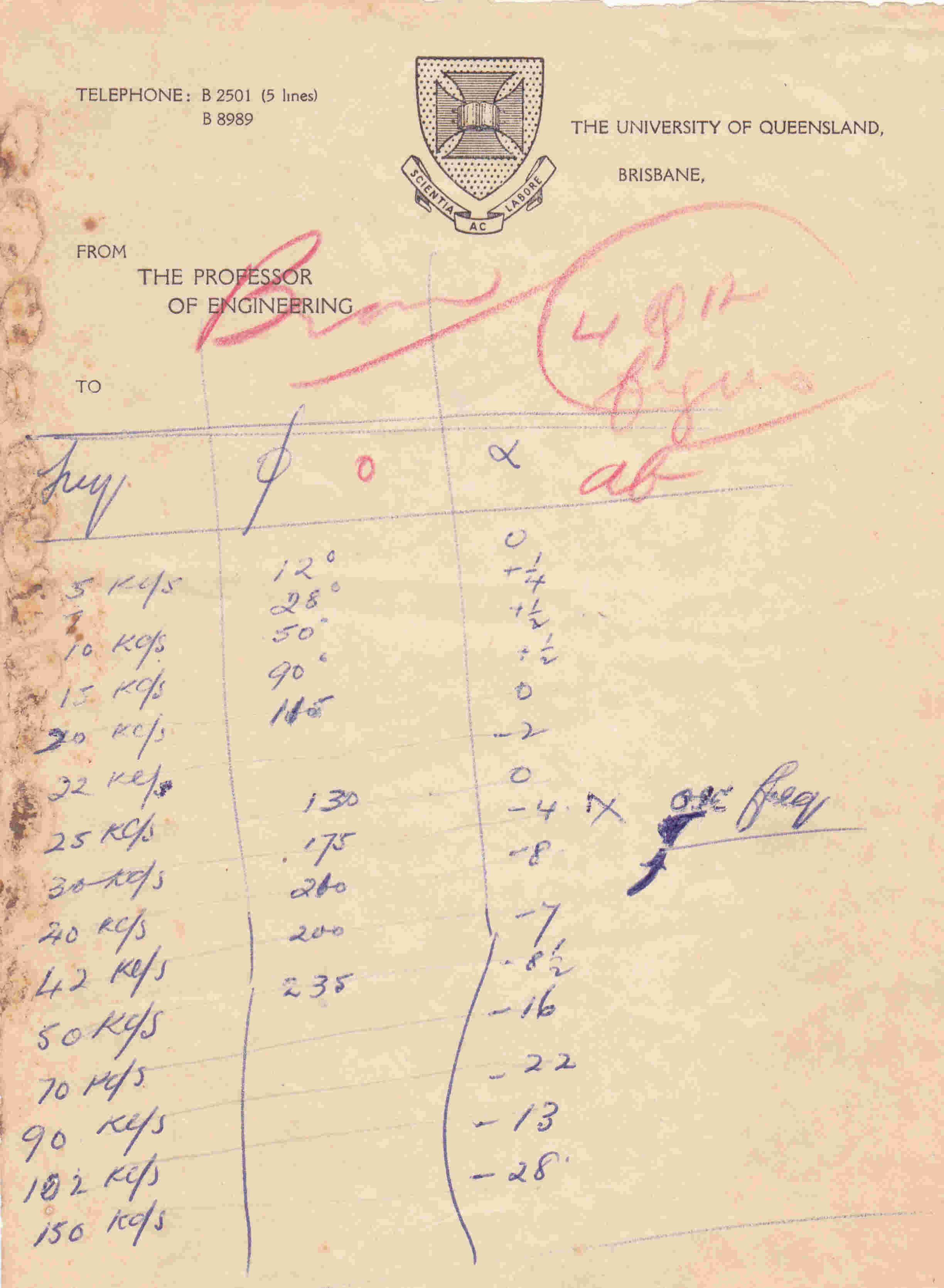 There are probably very few remaining records of the open
loop response of water cooled transmitters modulated at low level.
The open loop response of the 4QR transmitter was initially sent to me
by phone and copied down by a co-worker. It shows its age but has survived.
The test results are taken from the grid of the input stage to the output from
the then newly constructed high level envelope detector described above.
The amplitude and phase response is plotted opposite.
For audio in the fedback loop, th low level plate modulator, the two class B linear
amplifier stages and the diode envelope detector are effectively DC coupled.
Each stage has at least one high frequency pole, so the high frequency transfer
function will be of a much higher order than the low frequency one.
The high frequency response is, then, the limiting factor on stability, and so
it is the one which is plotted.
At about 30KHz the response is 3db down with a phase change of 180 degrees.
This corresponds to a system with many repeated poles on the real axis which
is consistent with the topology of the transmitter.
To accomodate the large degree of overall feedback required two Bode shelfs
were introduced into the low level audio stages.
The transfer function of the shelfs YB(p) is of the type given by:-
YB(p) = ( 1 + τ1p )/( 1 + τ2p )
where τ1 < τ2
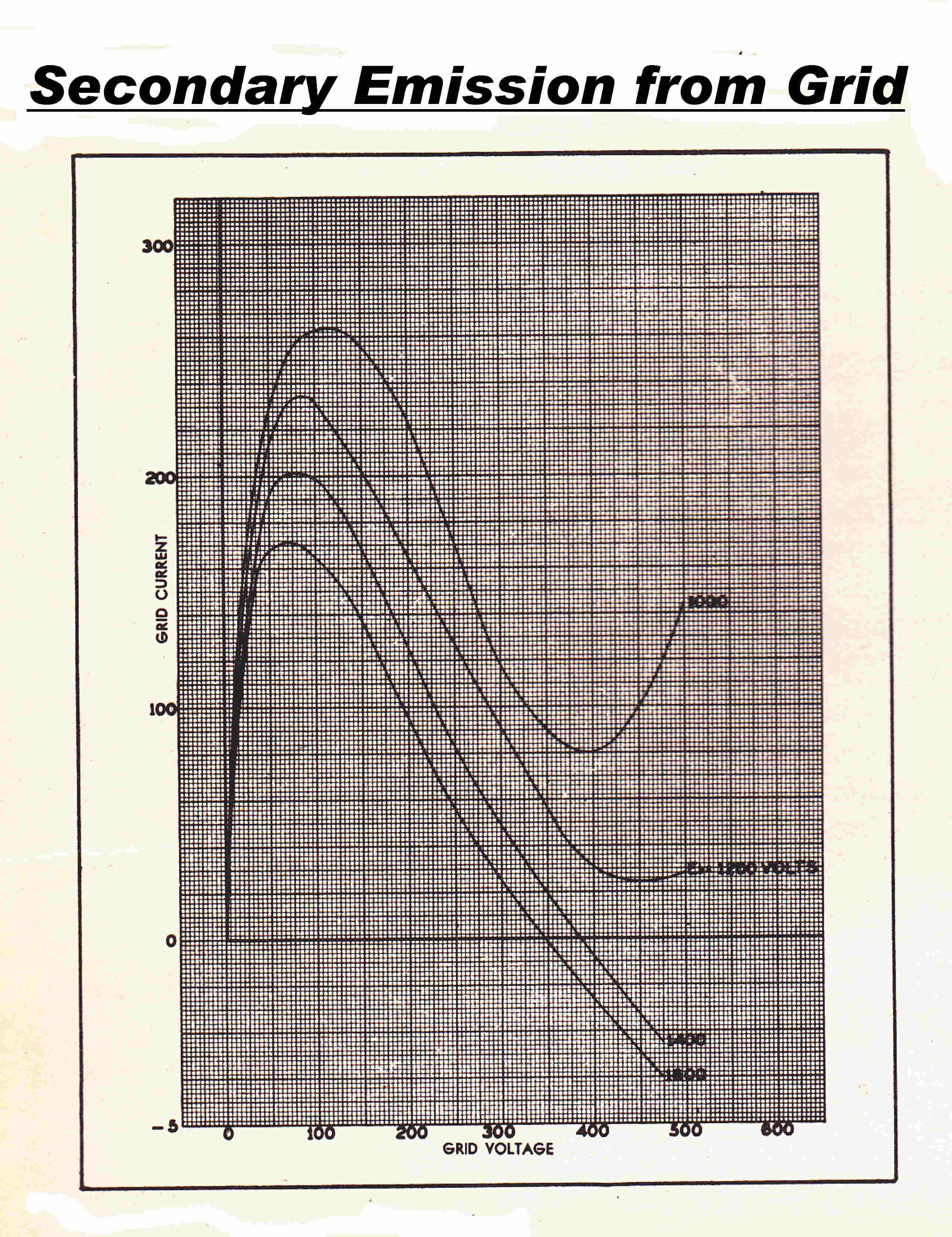 Grid emission is highly dependent on the processing of the grid surface
and is probably the most dificult parameter to control during manufacture.
A batch of output tubes with excessive grid secondary emission had been delivered for
use in the 4QR transmitter.
This was a major cause of distortion severe enough to overwhelm the corrective
effect of any overall feedback loop.
The behaviour of grid current in the presence of secondary emission is shown opposite.
As the positive grid voltage is increased, both the intercepted primary and secondary
yield are increased.
Eventually the emitted secondary current is greater than the primary intercepted
current and the external input current to the grid falls as the grid voltage
is increased.
This represents a NEGATIVE input resistance.
The wiring in the grid circuit has distributed inductance and capacitance, and so forms
parasitic resonant circuits.
If the negative resistance can overcome the losses in these, high frequency oscillation
will start until the amplitude is limited by some non-linear process within the tube.
This greatly affects both the grid and plate current and is the cause of gross distortion
on positive modulation peaks, when the grid of the class B stage is driven positive.
When the plate is at 1800 volts all the secondary electrons are collected.
As the plate voltage drops, space charge builds up between the grid and plate and,
eventually, some electrons are turned back into the grid, so the sign of the slope
reverses.
Secondary emission also has the disastrous effect of transferring heat dissipation
from the plate to the grid.
The heat energy delivered to the grid by a primary electron is given by:-
EP = e VG
where e is the electronic charge and VG is the grid voltage.
The secondary electrons are emitted with a very low initial velocity so their cooling
effect on the grid is negligible.
The secondaries then deliver an energy of e [ VP - VG ] to
the plate.
For non- secondaries the energy delivered to the plate is e VP, so the plate
dissipation is lower than VB IB and the grid dissipation higher than
VG IG. The grid may supply energy to the external circuit.
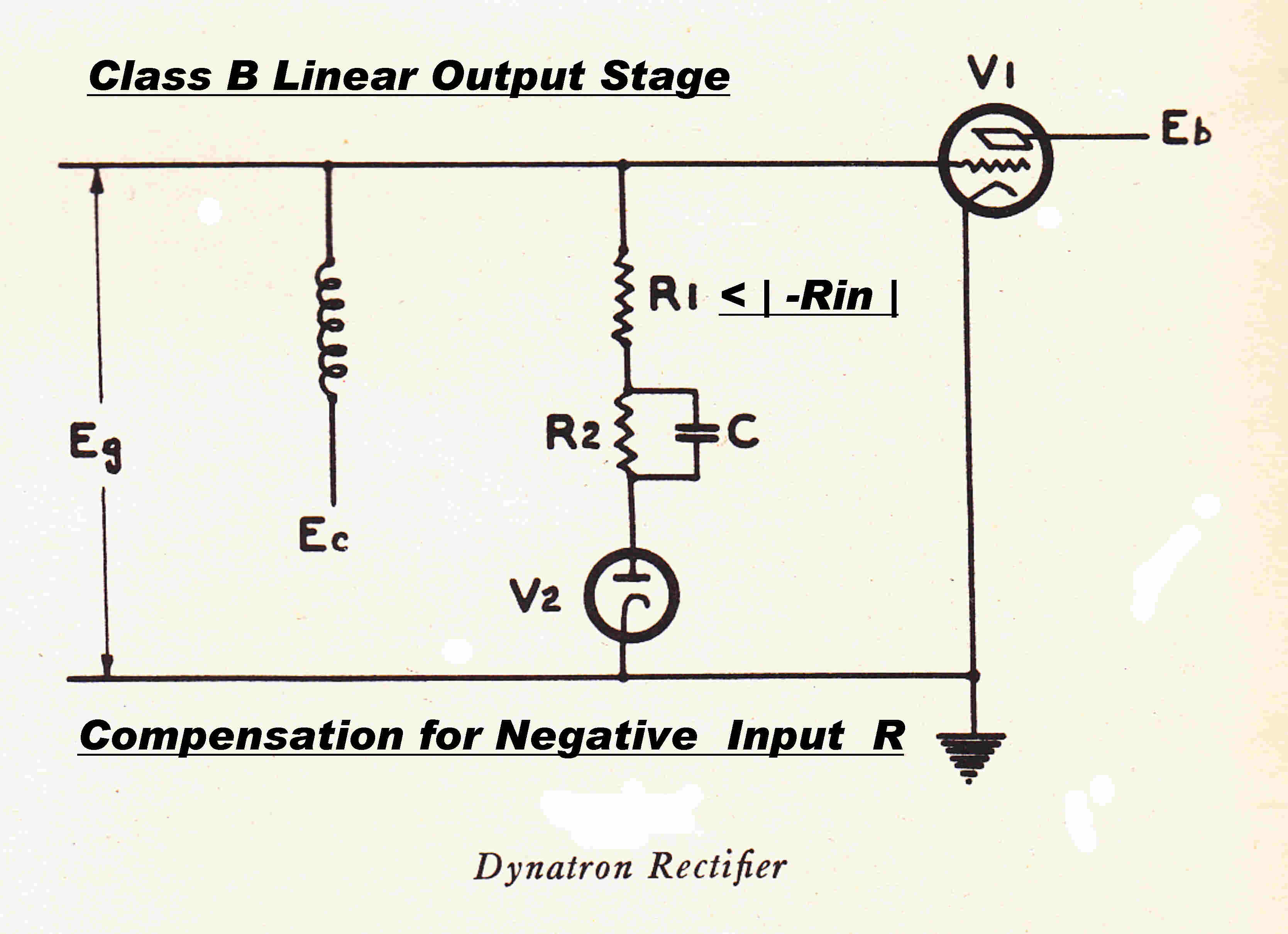 The class B linear output stage of the 4QR transmitter burst into
violent oscillation at 28MHz on positive modulation peaks.
This flattened the modulation envelope and caused gross even order harmonic distortion
way beyond the ability of any overall feedback system to correct.
The cure was to introduce positive resistance into the grid during positive modulation
peaks with a resistive load energised via a diode.
A typical circuit is shown opposite.
The resistor R2 and capacitor C generate hold-off bias in class C stages with
no modulation.
For class B linear stages the resistor and capacitor are omitted, since the
time spent with the grid positive varies with modulation.
If hold off bias is required, it must be generated by a regulated DC supply.
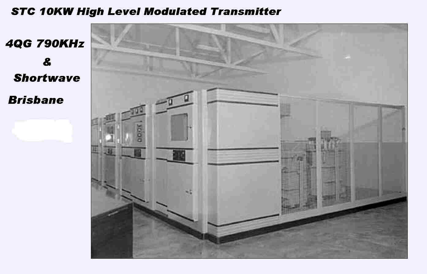 The 1948 10KW 4QG transmitter is shown on the right.
It is a classical plate modulated transmitter.
Although installed at the same time as the 4QR transmitter, it is different
in all aspects:-
[1] It has high level modulation in the plate of the final: 4QR was modulated
at low level with two class B linear amplifiers.
[2] The final was air cooled : 4QR was water cooled.
[3] The modulator was a 6KW class B audio amplifier with overall feedback taken
from the primary sides of the output transformer.
This was an attempt to reduce the insidious effect of cross-over distortion.
[4] The modulator drove the plate of the RF stage through the usual DC blocking
capacitor and iron cored choke. This was to keep the modulation transformer
free of DC.
[5] No envelope feedback was used, so the overall linearity was largely dependent
on the adjustment of the final stage and the tube characteristics.
[6] 12KV DC for the final stage was supplied from a six-phase rectifier using six
4078Z hot cathode mercury rectifiers.
The rectifier cabinet contained eight rectifiers - six active and two warm
replacements
[7] A compressor amplifier and peak limiter processed the audio input.
There was no compressor amplifier in the 4QR audio chain.
[7] The transmitter used tubes which were modern at that time 6J7 - 6V6 - 807
The output stage was a pair of 3J221 triodes.
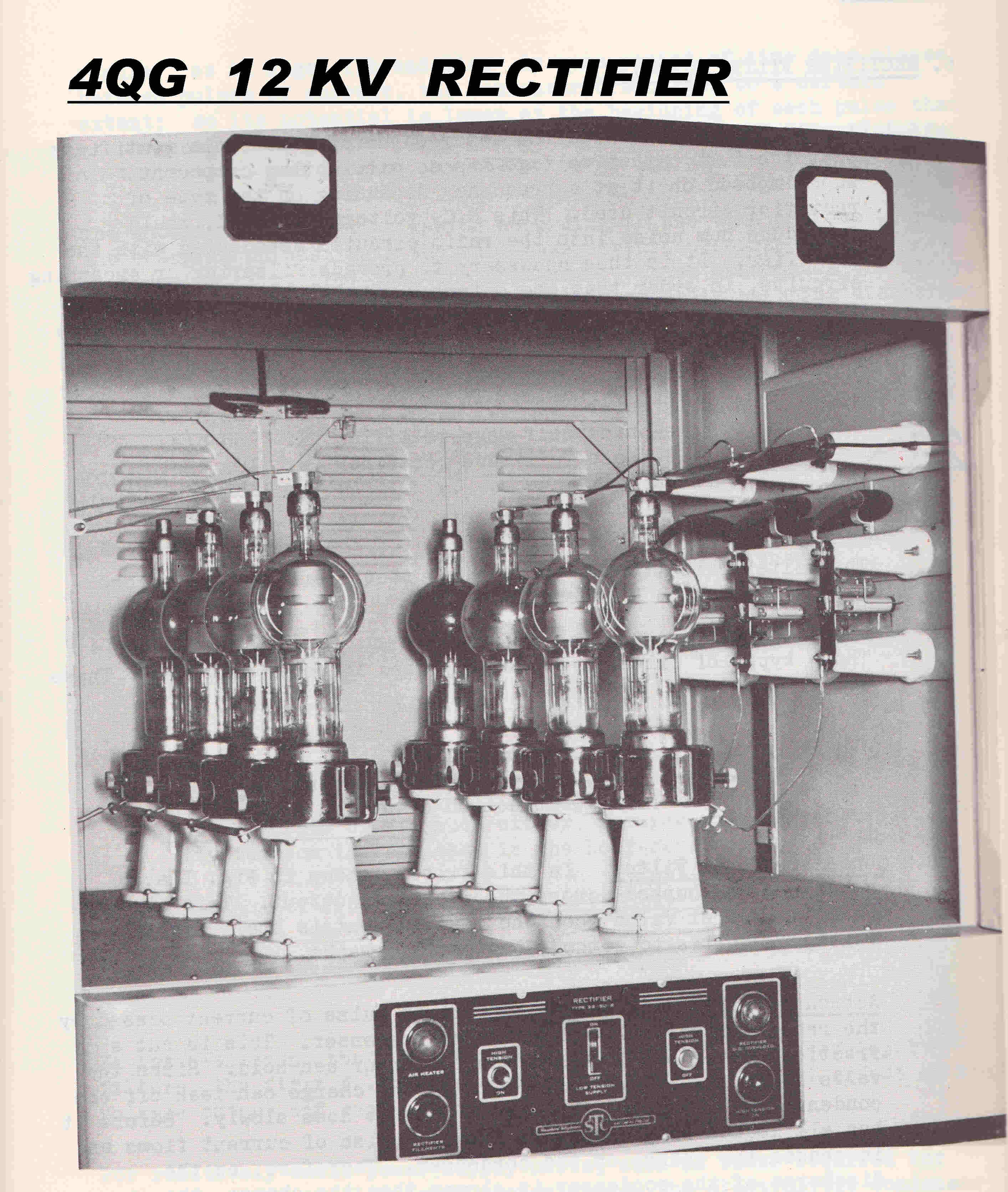 The 4078Z mercury vapour rectifiers in the six phase 12KV power
supply for the modulator and modulated RF output stage are shown on the right
The required mercury vapour pressure was not available at room temperature and
condensed mercury was usually visible on the side of the tube.
Filament voltage had to be applied to the tube for some time to increase the
temperature and mercury vapour pressure before HT could be applied.
The tubes were subject to the occasional arc-back.
They were usually replaced by solid stste rectifier stacks when possible.
The two spare warm tubes can be seen at the back of the enclosure.
Since the rectifiers carried the variable load presented by the modulator,
the blue light of mercury ionisation was modulated by the broadcast audio.
The topology of the high level plate modulated transmitter
settled down to a standard form regardless of the manufacturer.
Typical components of this standard form are described below.
 The class B modulators were perfectly symmetrical.
They were almost two separate amplifiers in parallel with one side handling the
the positive half cycle and the other the negative half cycle of audio.
Both sides were active during the crossover period.
It was pointed out in the design of the 6V6 amplifier, that parallel feedback
paths from either side of the primary of output transformers produces an amplifier
in which the balance is unusually sensitive to component drift.
The saving grace here is that, for most of the cycle, only one side is active.
The error signal applied to the grid of the output tube on the inactive side is
determined by the active side.
The voltage feedback is taken from the primary to minimise the destabilising effect
of output transformer leakage reactance and winding capacity.
High frequency feedback stabilising networks are added to the input stages as shown.
The input stages share common cathode and screens and this means that the open loop
response varies from the middle of the cycle with both sides active to the peak of
the cycle with only one side active.
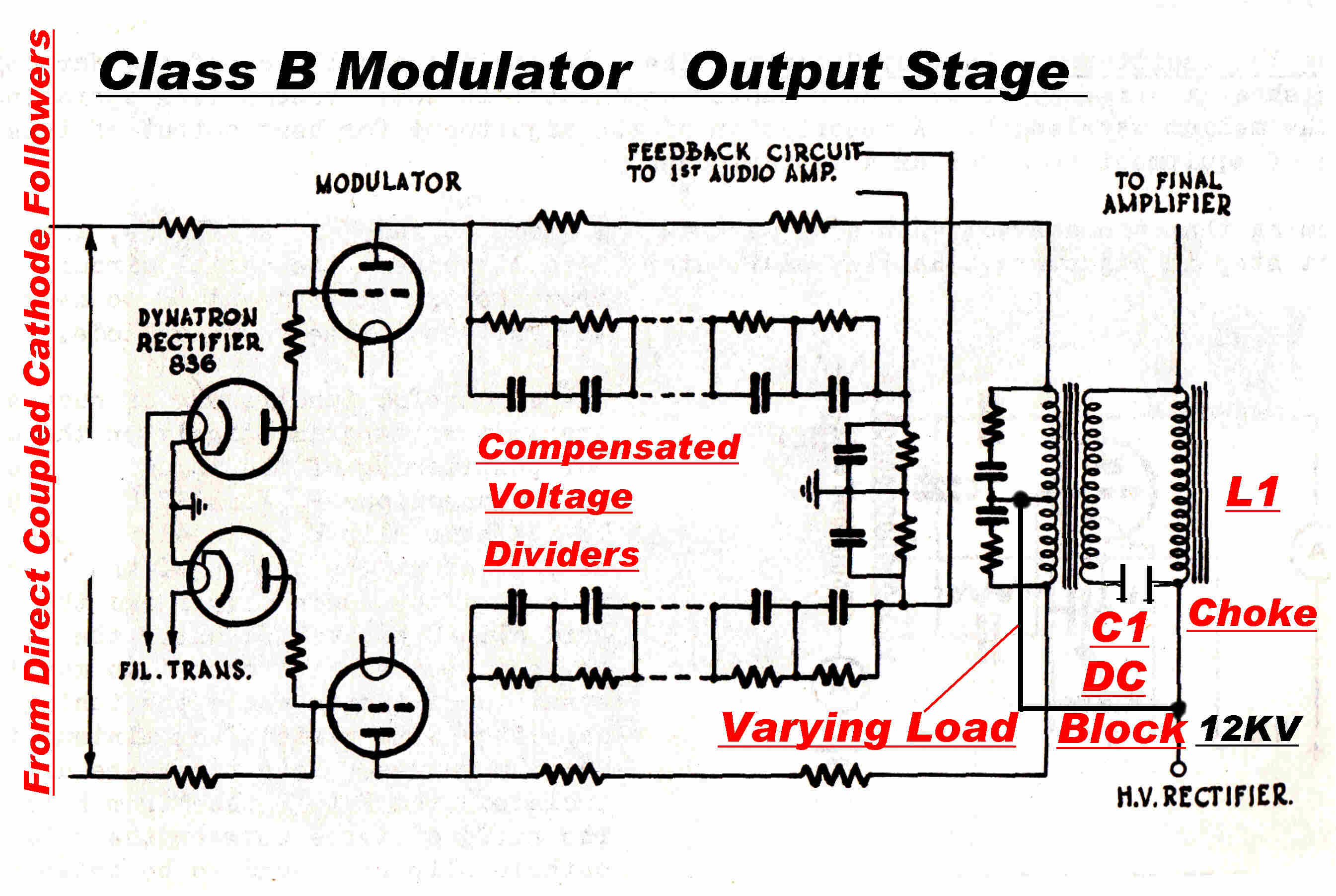 The variation of grid current of the output tubes over the modulation cycle
presents a highly variable load to the driver. This,then, nust have a low output
impedance.
In early transmitters the drive was through a step down transformer driven by triodes.
In later transmitters DC coupled cathode followers provided the low impedance drive and bias.
The bias is usually set to produce a standing current in the output tubes about 10% to 15%
of peak current. The value is a compromise between power dissipation and cross-over distortion.
The voltage swing on the plate of the modulator output tube is about +(-) 8KV.
The required feedback voltage is only a few volts. This is obtained from a compensated
resistive divider.
C1 blocks DC current to the RF modulated stage from the scondary of the modulation transformer.
DC in the secondary would demand a much larger iron core with a gap. This would incease the
winding size, the leakage reactance, the stray winding capacity and degrade the frequency response.
The modulation choke L1 present a high impedance to all modulating frequencies and a low DC resistance.
To decrease voltage stress on insulation, it is important to have the transformer primary,
secondary and modulation choke windings all at the same DC potential. Only the DC voltage drop
in the choke should appear across C1.
The low frequency performance of the modulator is not simple.
The resistive load presented by the modulated stage appears in parallel across L1. This forms
a series resonant circuit at some low frequency with C1, so there is a peak in the low frequency
response and decrease in the load impedance on the modulator.
To make matters worse, the modulator input current varies with signal and this induces transients
on the rectifier filter. These then provide spurious modulation.
The current drain on the HT rectifier is maximum at full modulation. The consequent drop in
output voltage causes a drop in the average carrier level. This is known as carrier shift.
In transmitters with low level modulation and class B linear amplifiers, the DC load is constant and
none of these peroblems arise.
 A typical plate modulated output stage is shown opposite.
It has been pointed out that plate modulation is linear only when the tube is heavily
"bottomed". That is when the RF plate voltage has to swing from high tension to zero,
so the envelope tracks the high tension voltage. Bottoming occurs when both the
RF load impedance and the grid drive are very high.
In a power output stage a very high RF load resistance cannot be used and plate
modulation is NOT an inherently linear process.
In general, to improve linearity either :-
[A] The grid bias should decrease as the plate high tension increases.
[B] The RF grid drive should increase as the plate high tension increases.
GRID BIAS VARIATION
If a fraction of the total bias is developd by a "grid leak", the total bias will increase as
the high tension falls, providing some correction for the modulation non-linearity.
The decreased plate voltage forces more electrons back into the grid, so the grid
current increases.
The grid current develops the bias across the grid resistor. The capacitor across the
grid resistor must be large enough to maintain the voltage throughout the RF cycle, but small
enough to allow the bias to follow the audio modulation.
RF DRIVE VARIATION
The RF drive to the grid of the output stage may be varied in two ways.:-
[A] The drive or penultimate RF stage may be partially plate modulated by picking
off a fraction of the modulator output.
This can be accomplished with a secondary winding on the modulation choke.
The modulation depth of the drive is under good control.
The disadvantage is that the secondary winding is at a lower DC potential
than the main winding and extra insulation and cost are encountered.
[B] The effective input impedance looking into the grid of the output stage falls
as the DC input falls. This is because of build-up of space charge between grid
and plate. This deflects electrons back into the grid.
A grid drive from a high output impedance causes the drive amplitude to fall
as the input impedance falls - the required condition.
Since the grid characteristics of the tube depend on secondary emission, any
linearising "fudge" depending on final grid current is not attractive.
Properties depending on secondary emission are notoriously variable
from tube to tube.
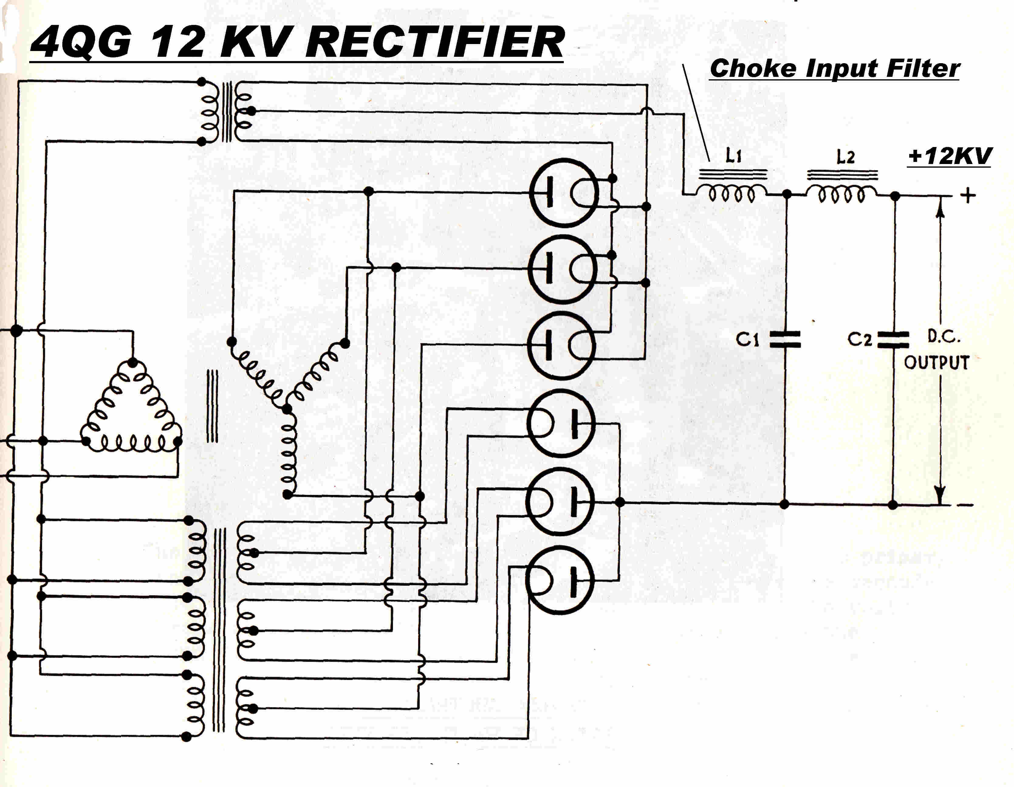 The circuit for the six phase rectifier and filter is shown opposite.
In mercury vapour rectifiers, negative electron space charge is cancelled by positive
mercury ions.
The voltage drop is then constant at about 15 volts and determined by the ionising
potential of the mercury atom.
To limit currents, the rectifiers must operate into a choke input filter L1. This is
above critical inductance, so the rectifier plate current is a series of rectangular
pulses.
The incremental resistance of the mercury rectifiers is very low, so the output resistance,
and hence the regulation, is determined by the resistance of the transformer and chokes.
The output impedance will also be highly frequency dependent and exhibit
peaks and troughs.
The load current has three components:-
[A] A variable DC load current presented by the class B output stage of the modulator.
[B] A load current of twice the modulating frequency presented by the classs B output stage.
[C] A load current of the modulating frequency presented by the RF output stage.
Any low frequency transients on the output appear as spurious modulation on the carrier.
Poor regulation causes the DC output to drop with modulation and with it the carrier level.
This is known as carrier shift.
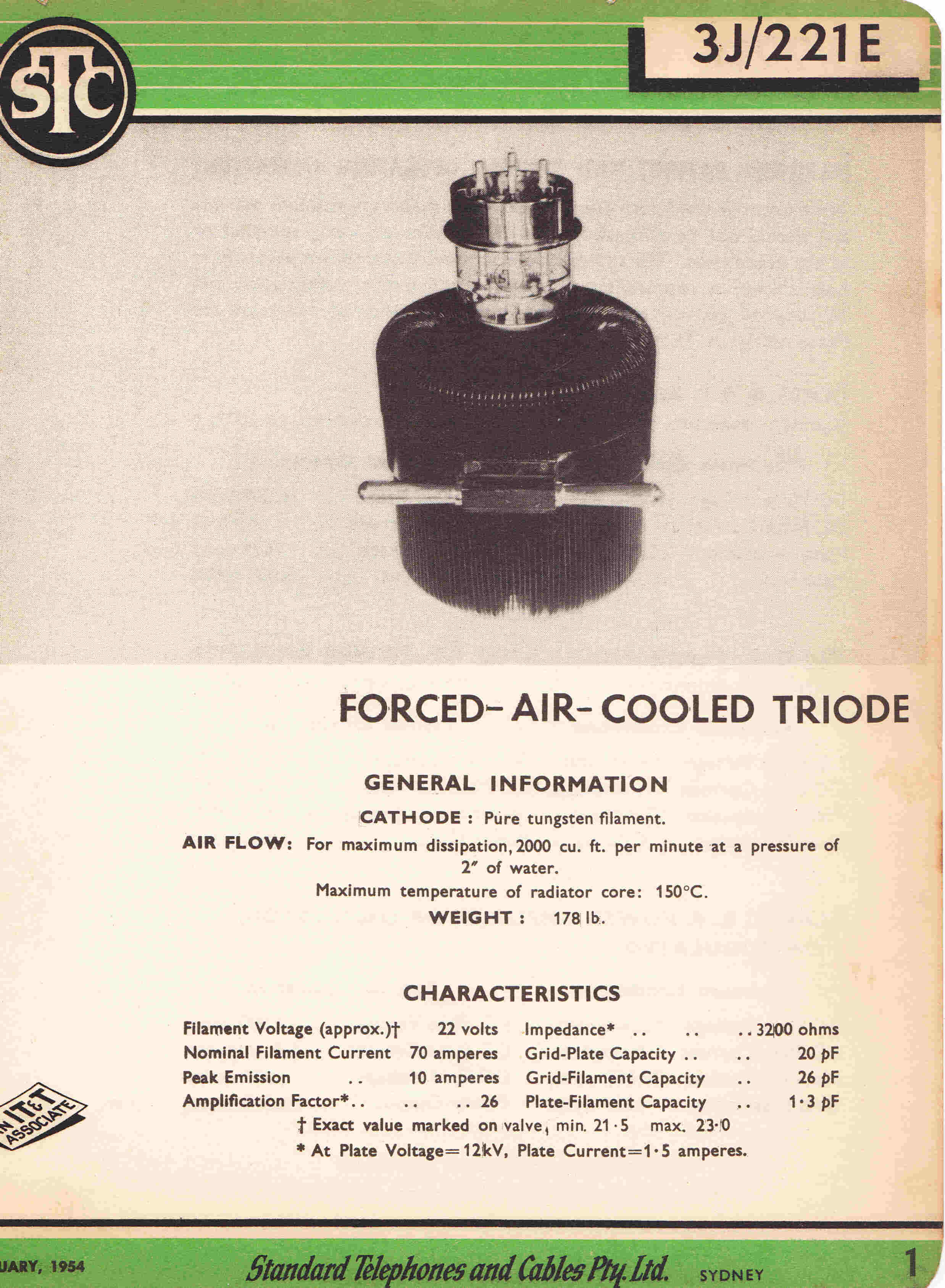
|
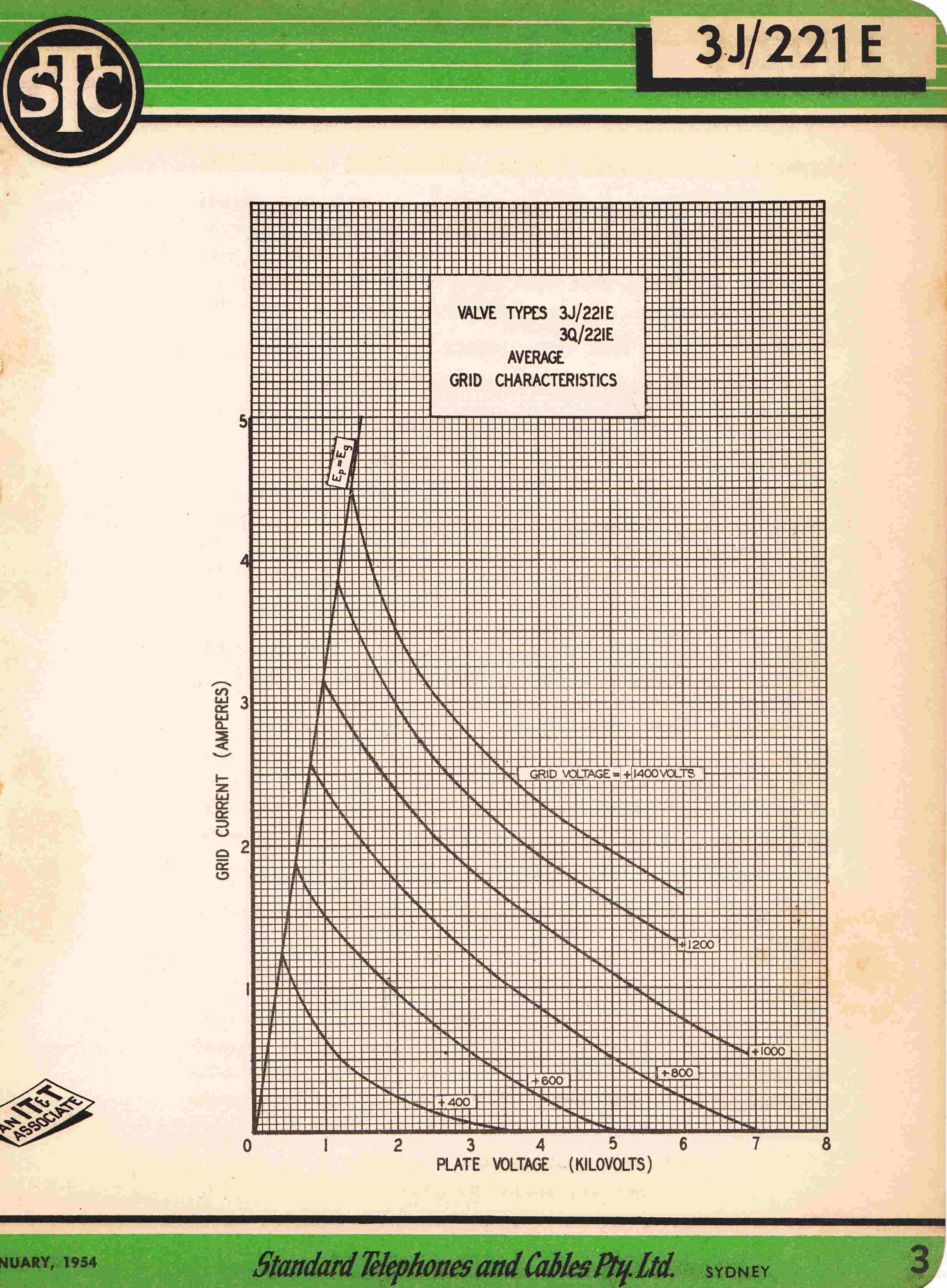
|

|
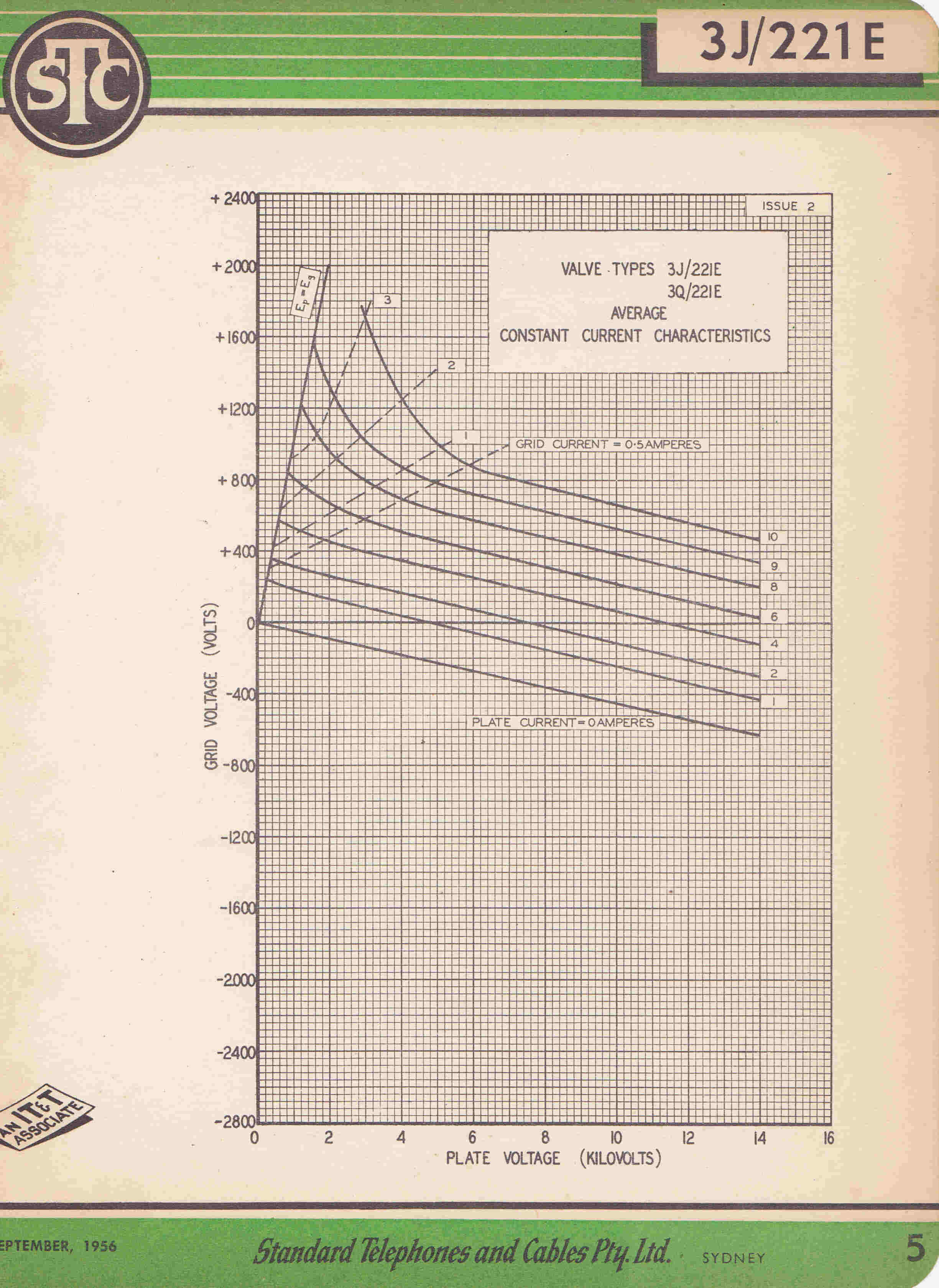
|
|
|
|
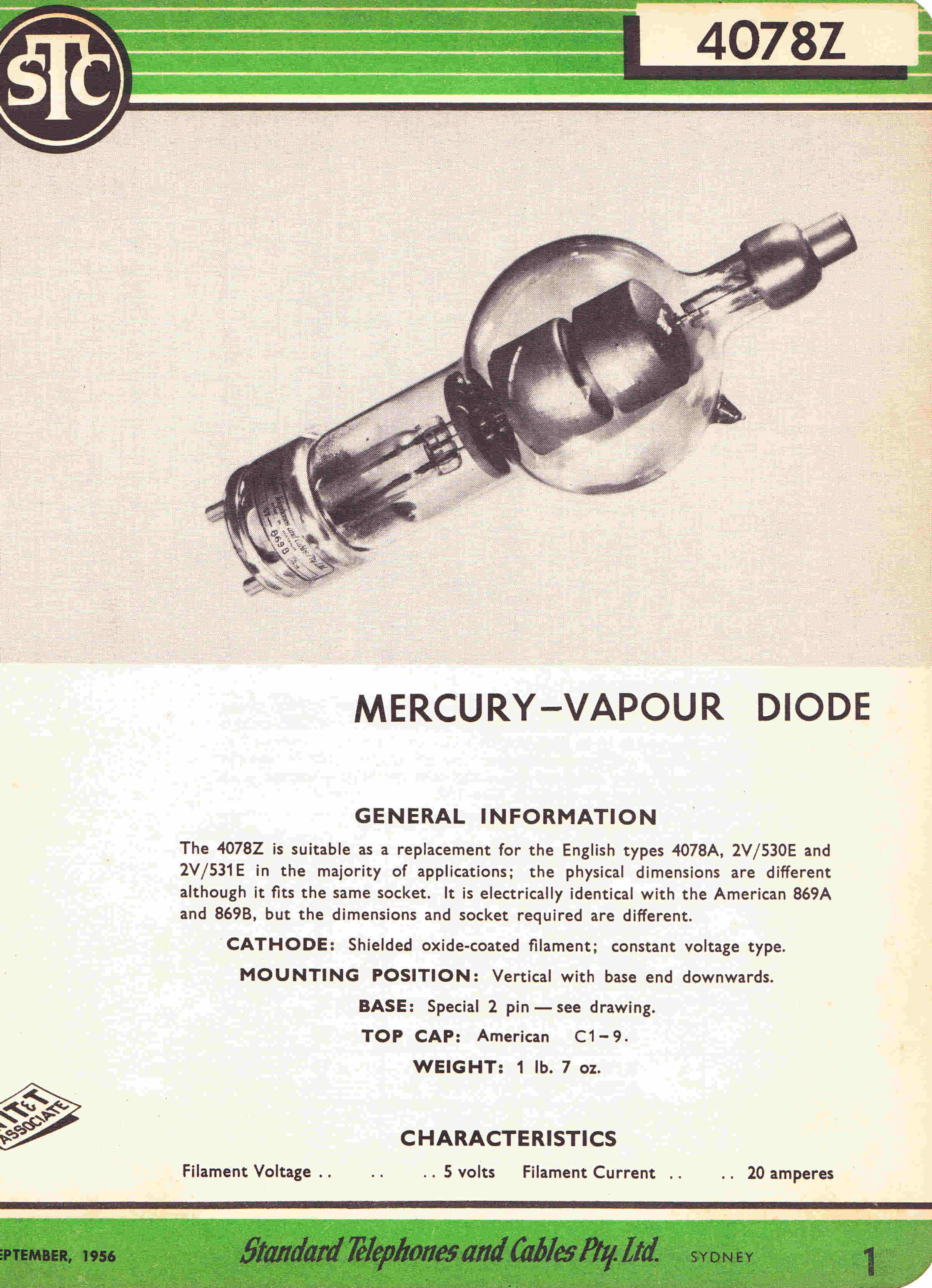
|
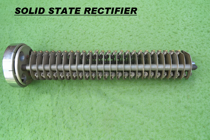
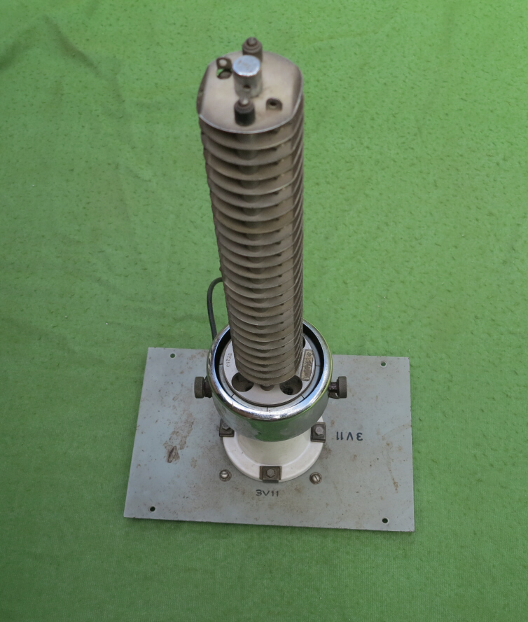
|
|
THE 4078Z MERCURY VAPOUR RECTIFIER
|
THE SOLID STATE REPLACEMENT FOR THE 4078Z |
The following is a recording of this transmitter received on a wideband
low distortion vacuum tube tuner.
The IF frequency of the tuner was 1.9MHz.
The envelope detector was a 6H6 diode driven at high level by a 6V6
IF output stage with RF feedback.
The oxide is starting to part from the tape.
It is not known if this is causing deterioration in the audio quality,
but it is believed that it is a reasonably fair approximation to the original sound.
It is noteworthy that turntable rumble managed to make its way through the
modulation trnsformer and choke.
During extensive testing of AM tuners in the mid 1950s I became interested
in the waveforms of the announcers' voice and particularly in male announcers.
It is pretty hard to beat the quality of a rich low male voice, yet the accompaning
waveform seems the least desirable as modulation content for any transmitter.
It usually consists of a series of unidirectional spikes.
The waveform of the male announcer in the above extract is shown below.
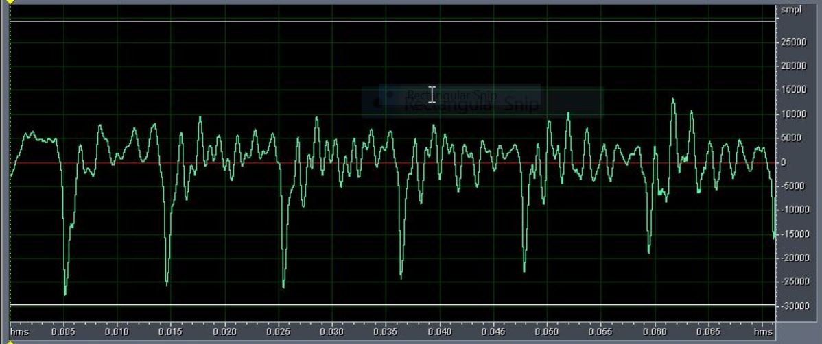
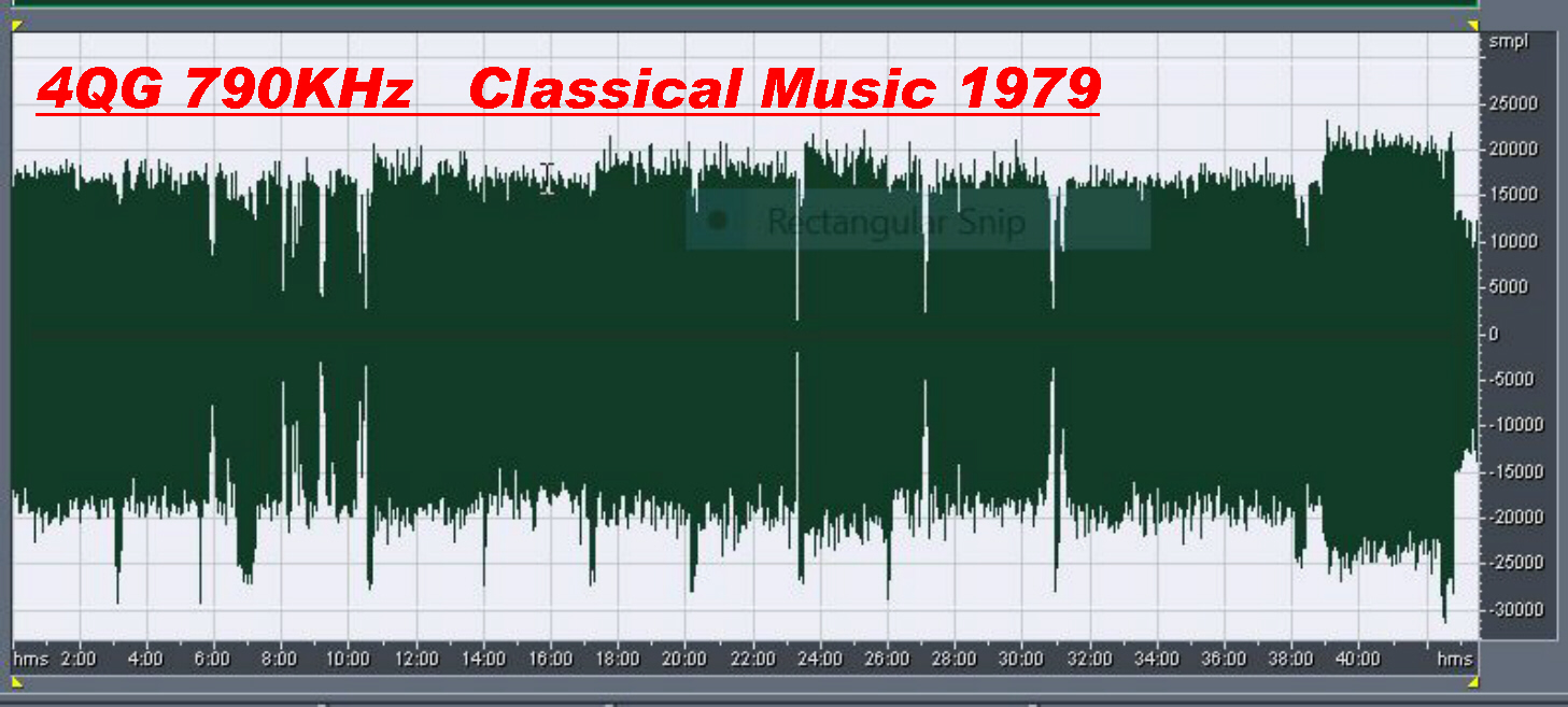
|
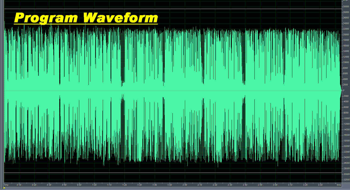
|
|
In the older transmitters the average level of modulation was set lower to accomodate
peaks. |
These days the audio is digitally processed, so that all peaks are the same regardless of content. |
In the late forties I had the privilege of talking to professional electrical
engineers in communications.
In discussing audio recording and transmission systems they invariably mentioned the
"5" rule - 5% distortion and a 5KHz cutoff.
This seems to have influenced the design of most - but not all - vacuum tube broadcast receivers.
The receiver design then set the acceptable limits on transmitter performance.
Little gain was to be made catering to a very small minority with broadband low distortion tuners.
In this sense, high level plate modulation with a class B amplifier was good enough.
The only exception to this seems to have occurred at WLW :-
Cathanode Modulation System by R. J. Rockwell [ Chief Engineer of WLW ]
IEEE Transactions on Broadcasting : Vol. BC-11 No.1 Jan. 1967 pp - 10 - 30
Note: This transmitter was, still, essentially plate modulated with heavy RF envelope feedback.
The forward path transfer function was made more conducive to feedback by omitting
the modulation transformer and using direct coupling between the class B modulator
and RF output stage.
Some rather odd circuit design made it very difficult to set up and adjust,
so it fell into dissuse.
Note: There is a section at the end of this page describing much simpler methods ( using
parallal loops ) of applying envelope feedback to plate modulated transmitters.
The limitations of various sections of the typical vacuum tube AM receiver are now discussd.
A few receiver manufacturers - notably Breville and Airzone - designed circuitry often much
better than the accepted standard.
At the transmitter the audio passed through a 10KHz sharp cutoff filter :
most receivers had an effective modulation bandwidth of about 3KHz.
[ Note: Some solid state AM receivers of Asian origin now have a bandwidth of 1.8KHz!!! ]
A few receivers had a variable bandwidth IF strip ganged to the tone control to give
a maximum modulation bandwidth of 5KHz.
Both the Breville and Airzone receiver described below had this facility.
This is fully discussed in the section on the Airzone Mantel Receiver and need not
be repeated here.
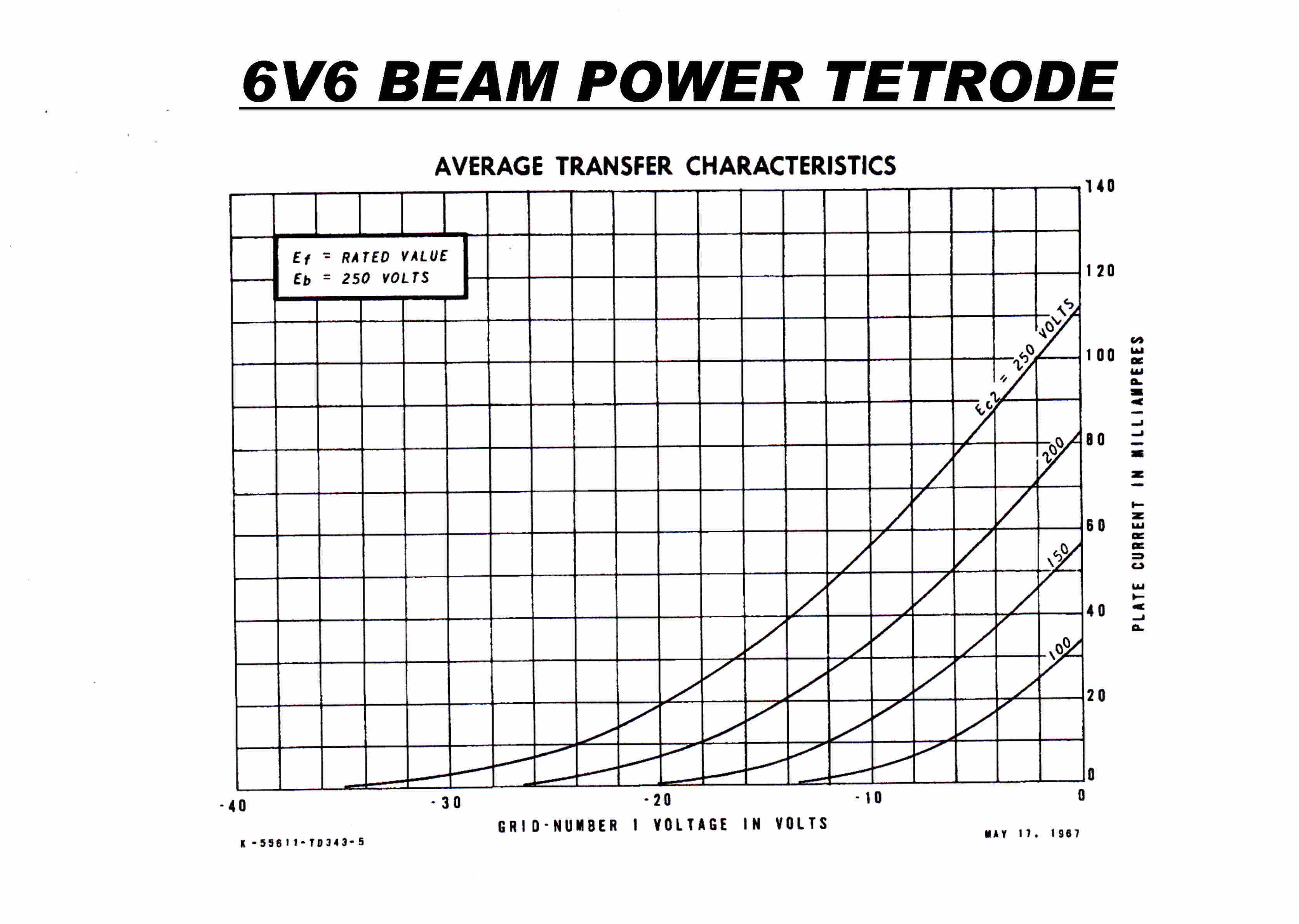
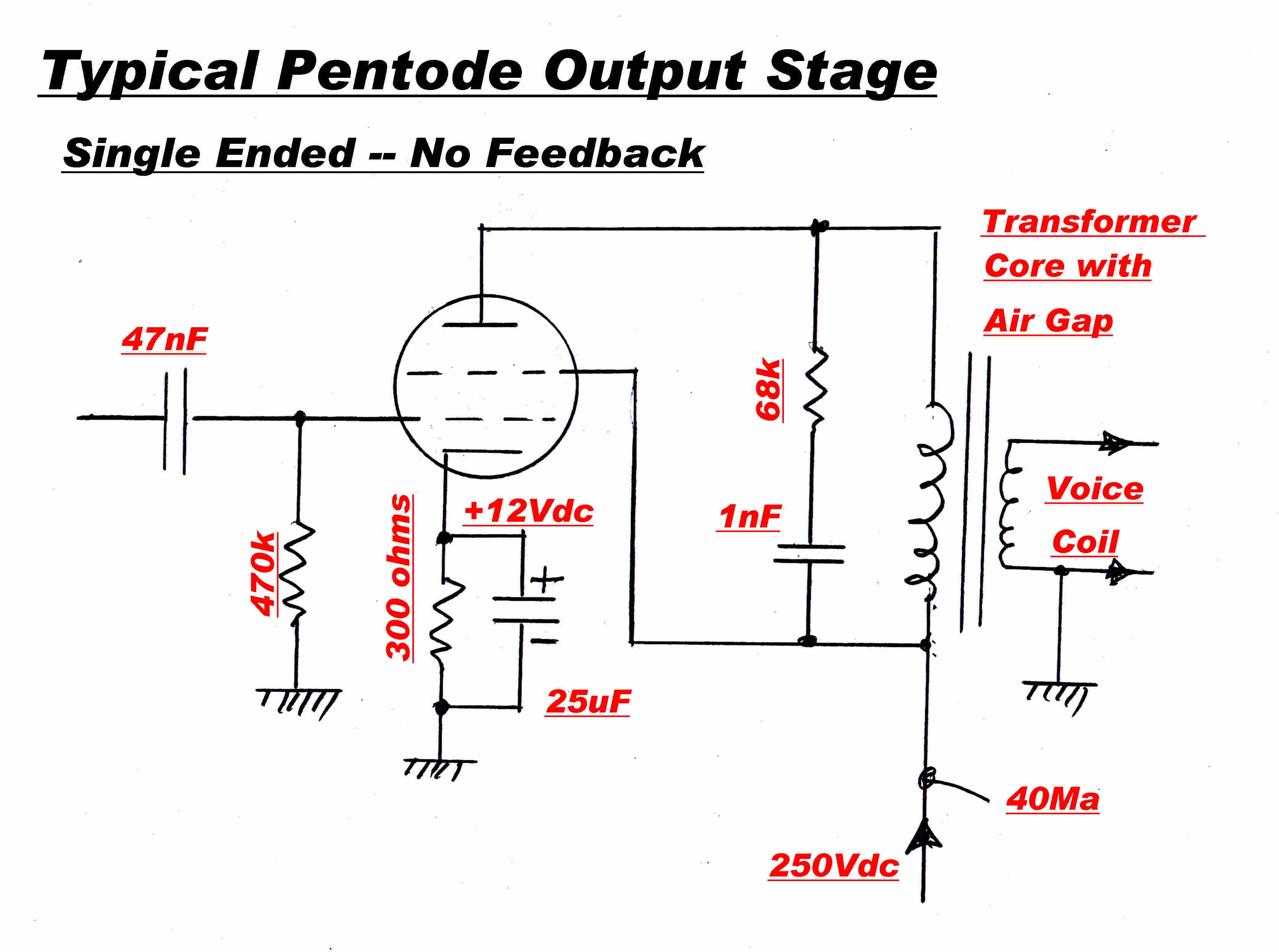 The audio output stage in most receivers was a single class A pentode
with no feedback.
The pentode was usually a 6V6 or equivalent (6AQ5). The transfer characteristic
( IP / VG ) is also shown.
This exhibits greater non-linearity than the modulation characteristic of any plate
modulated transmitter and is only one of the stages in the receiver causing distortion
- far worse is to come around the detector and AGC generation.
The quoted distortion for the 6V6 is 7.5% at 4.5 watts output.
The DC plate current ( 45MA ) in the primary of the transformer is also highly
undesirable. To prevent saturation an air gap is inserted in the core. This increases
the leakage inductance and decreases the primary inductance. Moreover, the primary
magnetising curve is no longer symmetrical - adding to the low frequency distortion.
Note that the single ended output stage in the Airzone mantel rceiver had overall feedback.
The Breville 239, designed in 1940, had a full push-pull output amplifier with feedback.
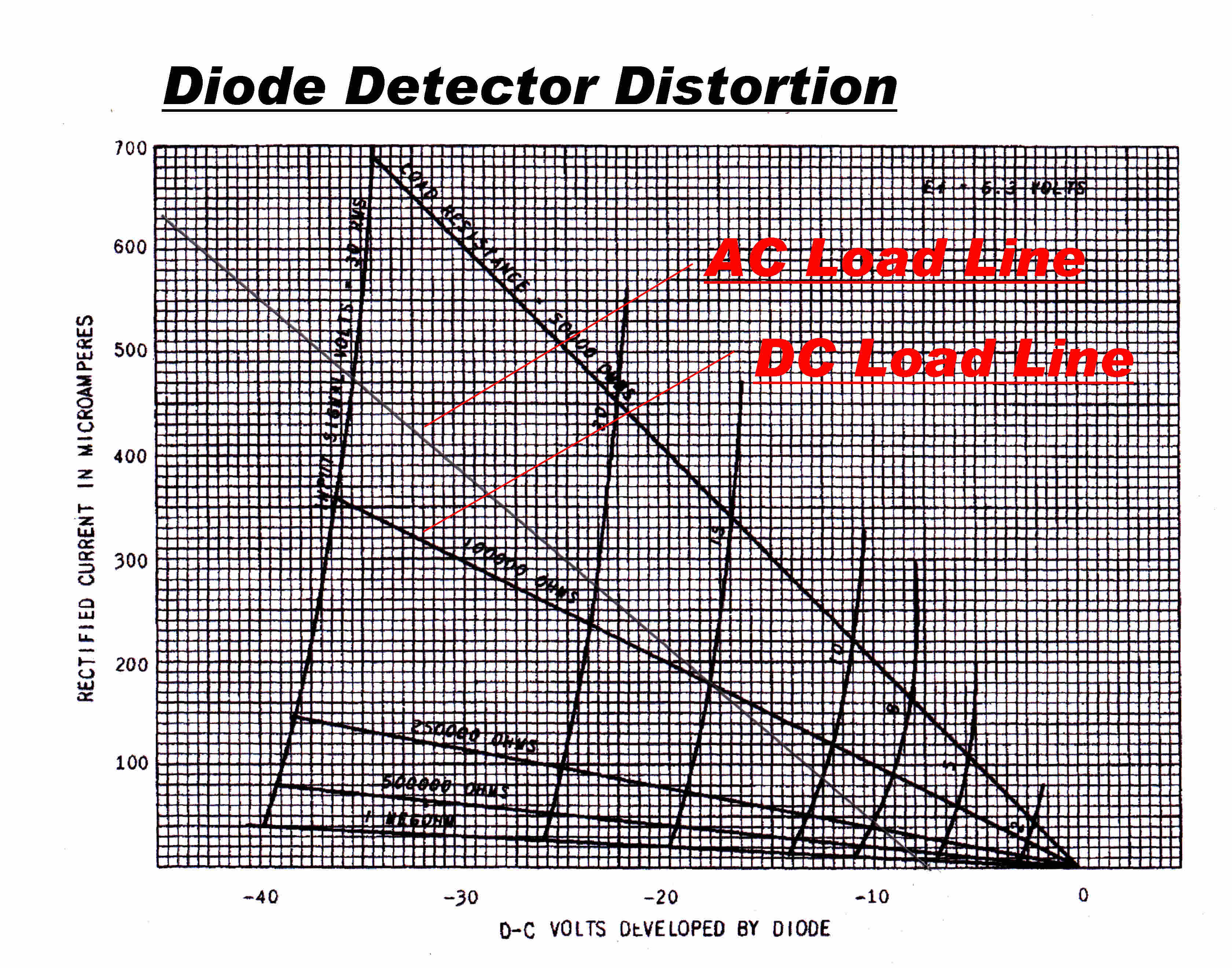
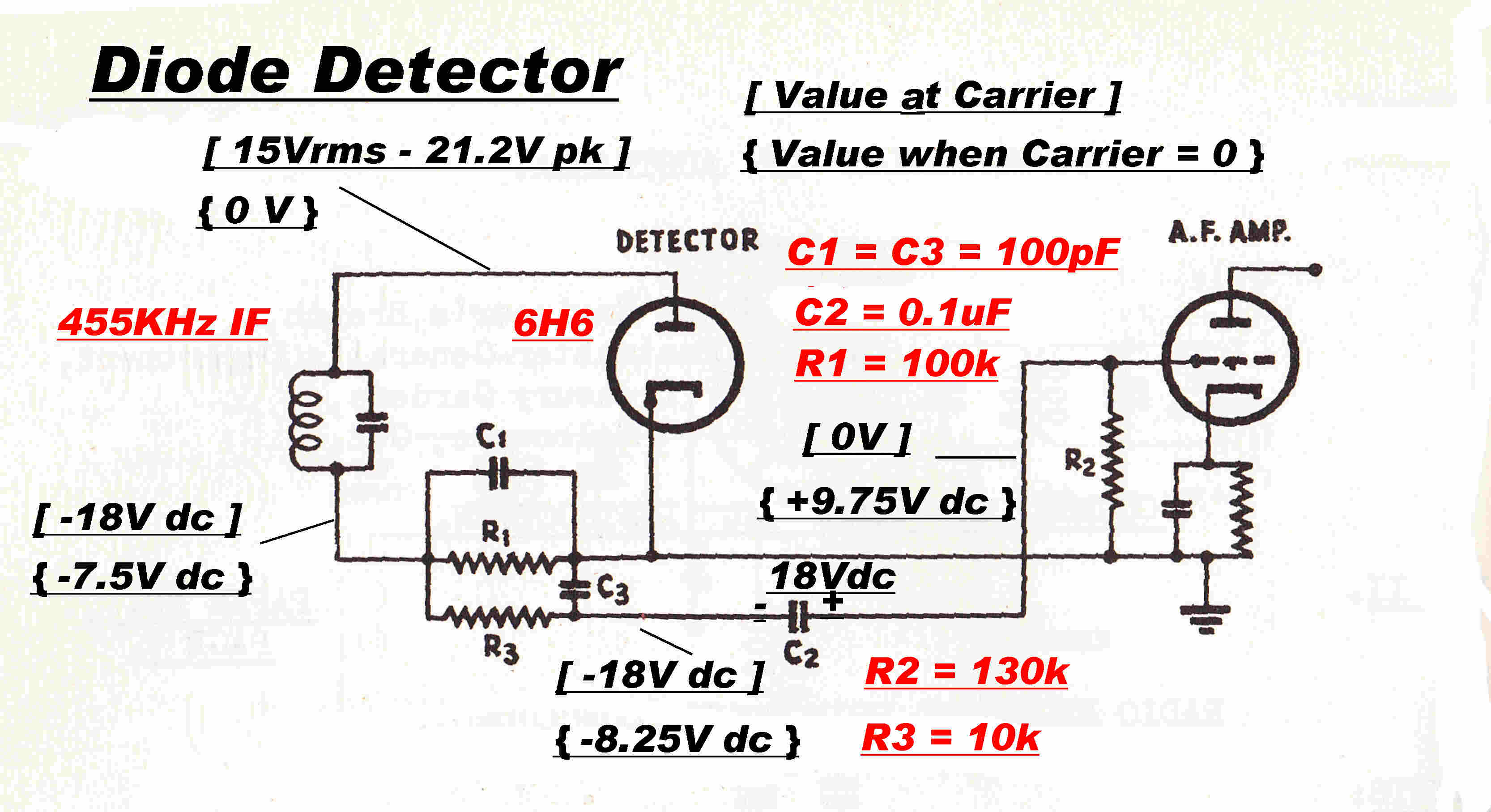 Diode detectors follow the opposite law to most devices - the greater the
RF or IF drive the less the distortion - providing there is no distortion in the stage
supplying the RF drive.
If the AC load on the detector is less than the DC load, the detector will clip the
negative peaks of modulation and produce horrendous distortion.
Surprisingly, almost all vacuum tube receivers suffered from this defect although,
for a small amount of trouble and cost, it was easily avoided.
A typical diode detector is shown opposite.
R1 is the DC load. R2 and R3 in series the AC load. C2 is the AC coupling capacitor
and C1 and C3 small bypass capacitors.
A carrier voltage of 15Vrms (21.2Vpeak) is applied to the detector.
From the diode [6H6] curves the DC output from the detector is -18V.
The AC load line is also shown and intersects the x axis for a carrier input of 5Vrms.
For RF inputs less than this there is no change in output from the detector, so the
demodulated signal is clipped.
The clipping occurs at a moulation percentage given by: [( 15 - 5)/15] x 100% = 67%
The distortion mechanism can be explained in more detail:-
The carrier DC output of -18V is maintained across C2.
When the carrier disappears on negative modulation peaks, the voltage
on C2 distributes itself across R1, R2 and R3.
-7.5V appears across R1 -- biasing the diode off and disabling it
until the carrier level rises to 5rms volts.
Carrier condition voltages are included in [ ] brackets. { } denotes no carrier.
At this point it is profitable to study the design of two
Australian designed AM receivers.
The design of both receivers is above average.
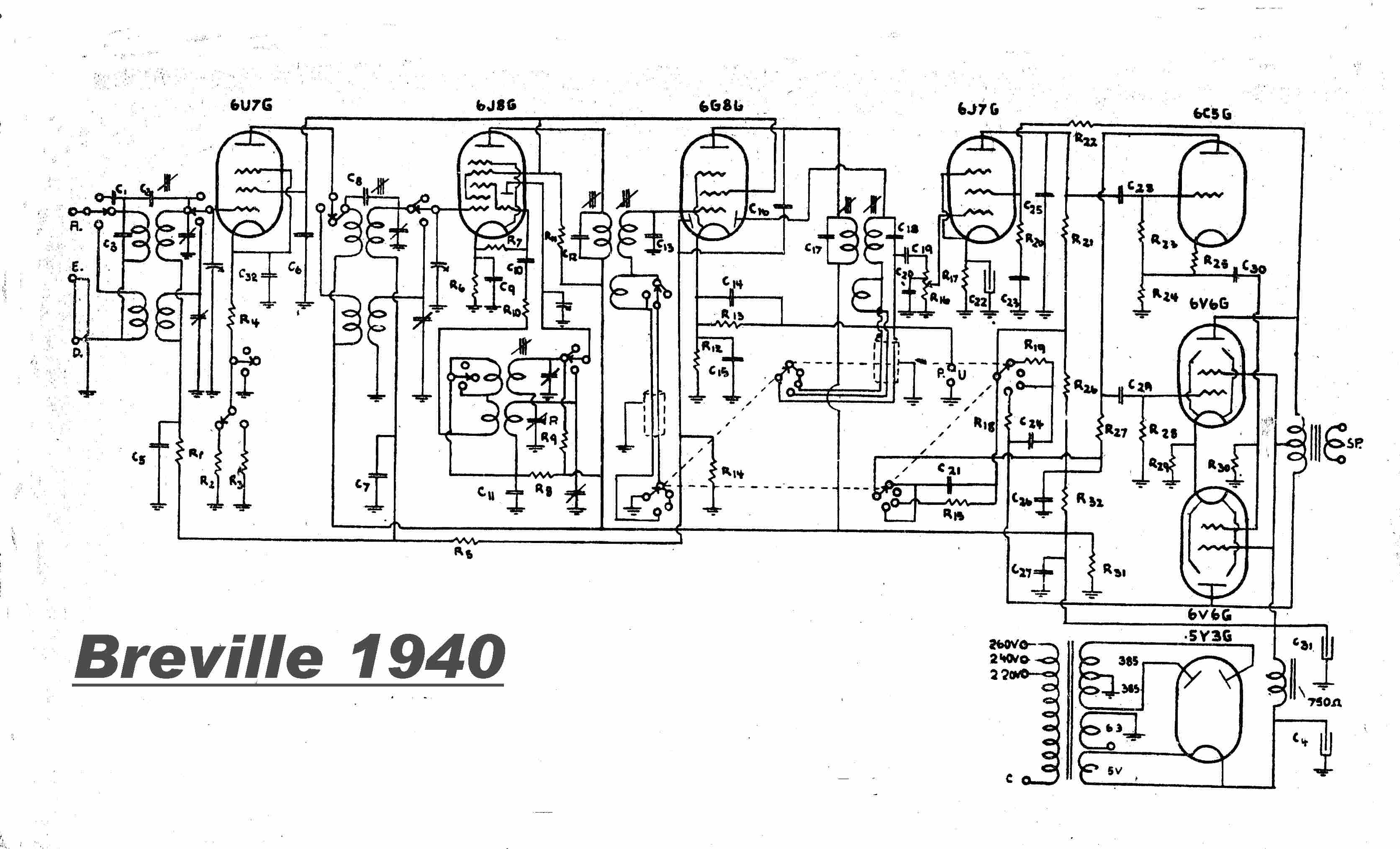

Note: For a detailed discussion of the Airzone receiver:-
SEE AIRZONE RECEIVER
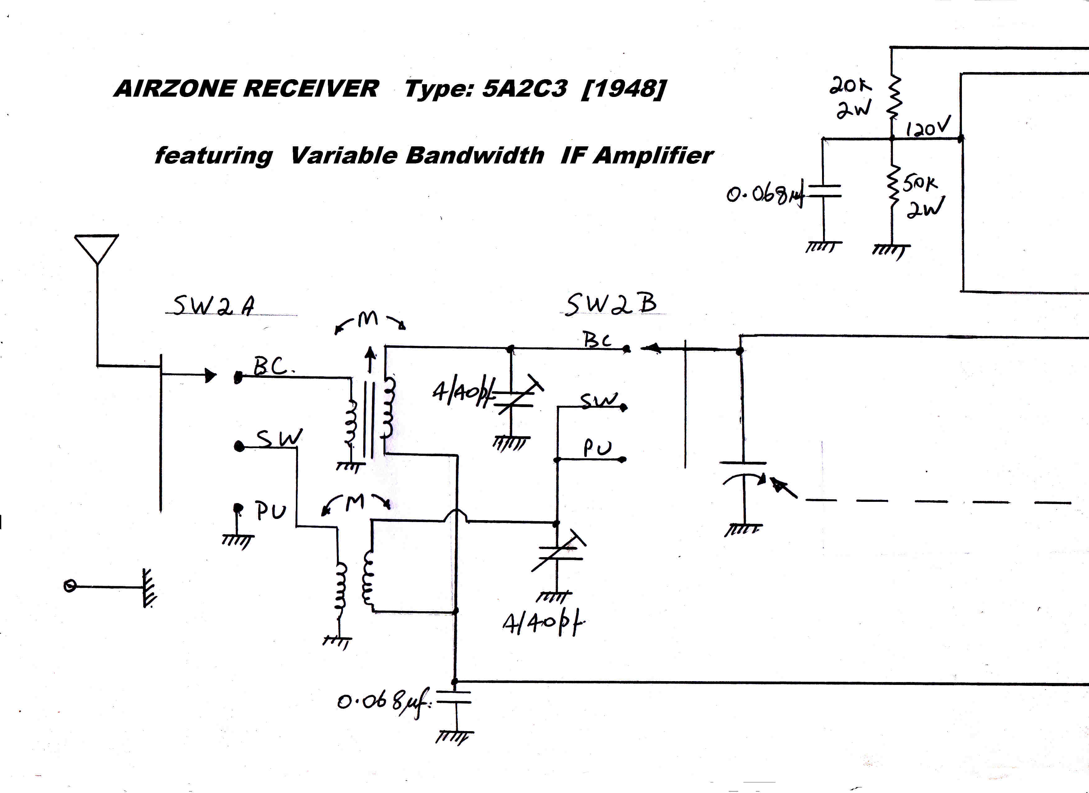
|
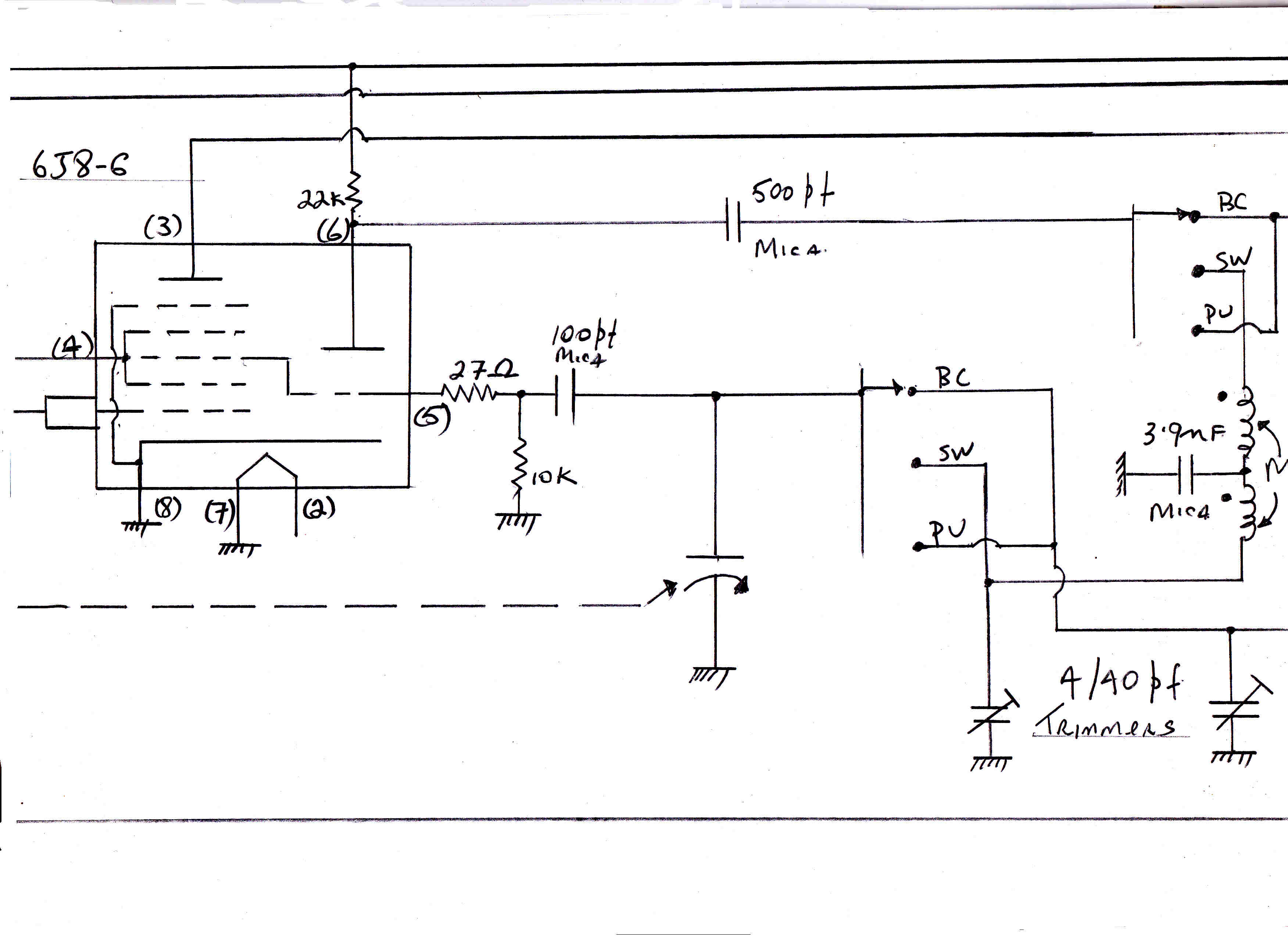
|

|
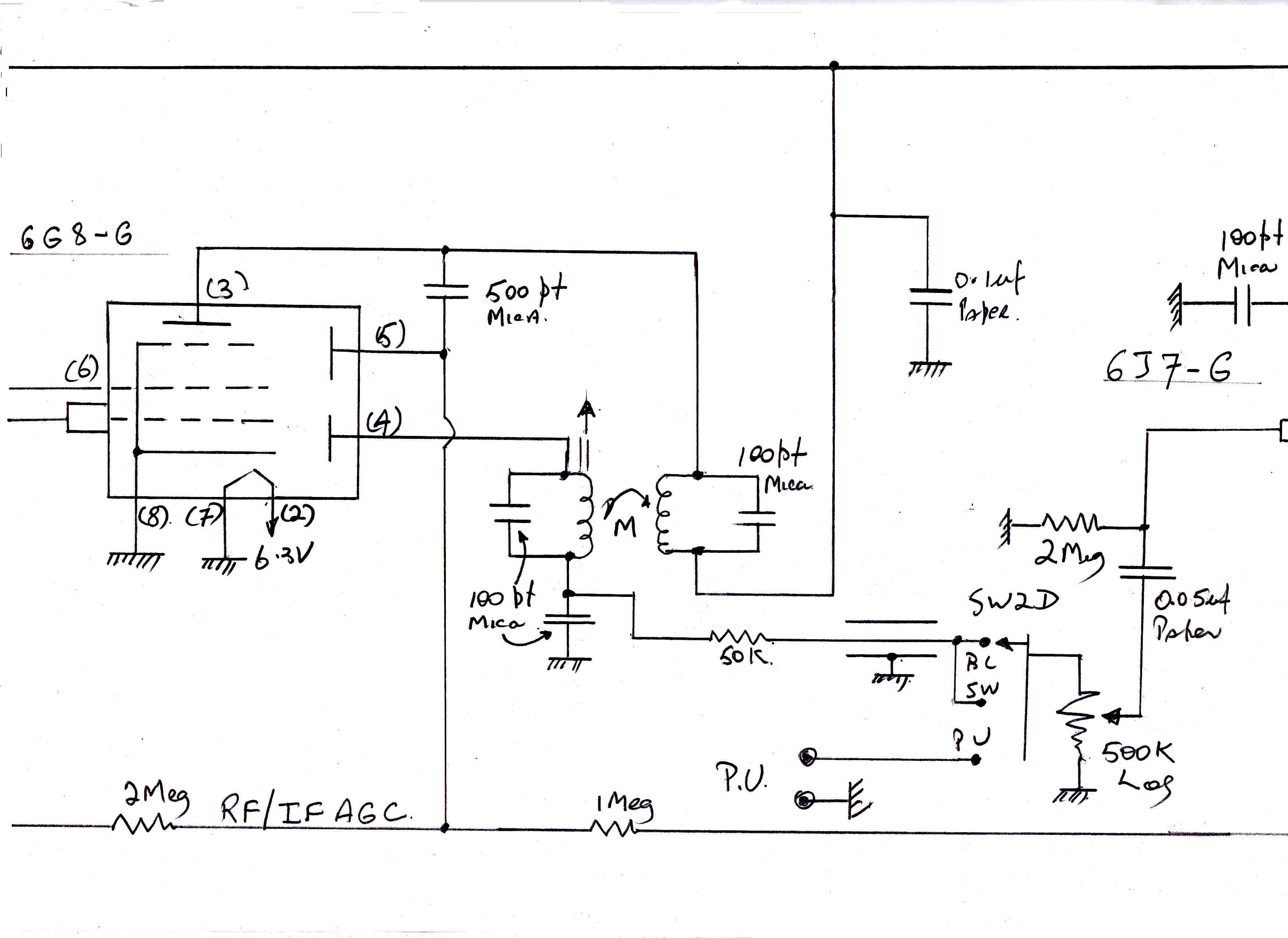
|
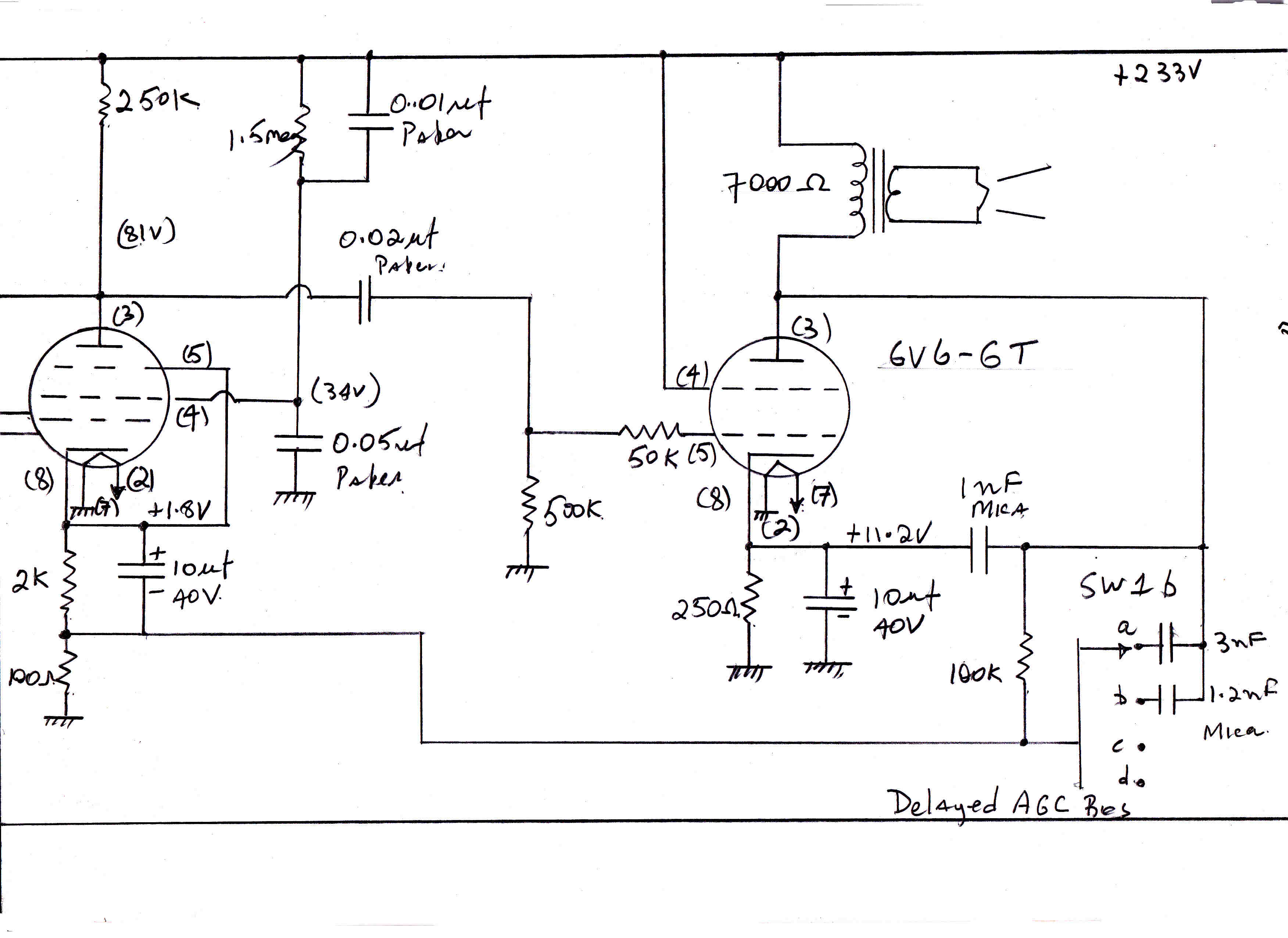
|
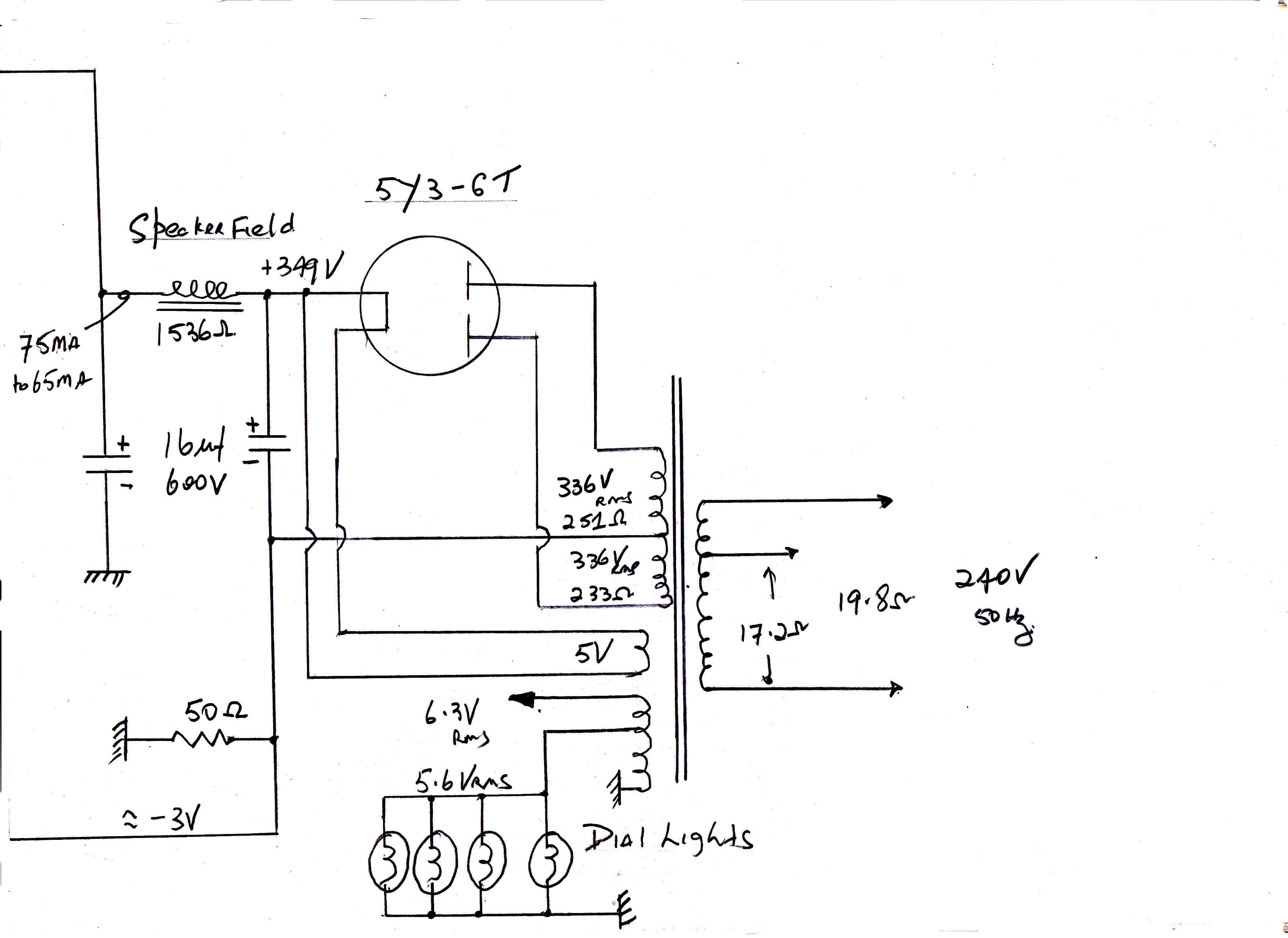
|
In the 1940 Breville, the diode dectector DC load is R15 30k,
the AC load is the potentiometer R16 500k.
The AC load is then 28.3K and the ratio Rac/Rdc = .943
This greatly exceeds the value found in most receivers of the day.
Remember that this is a high quality receiver with a push-pull output
amplifier.
The 1948 Airzone offers a different solution.
The DC load on the detector is 550k ohms. The maximum AC load is 2Meg ohms,
but this almost never appears across the detector, because the DC load is
also the level setting potentiometer. The audio output from the detector
is usually over 5 volts, so the wiper is usually set towards the bottom of
the pot. thus minimising the loading.
In the Breville 239 no AGC is applied to the 6G8 IF stage,
so that it always operates with a high plate current, and so is able
to drive the diode detector at a high level without distortion.
AGC is applied to the 6U7 RF amplifier and the 6J8 converter.
This gives adequate control.
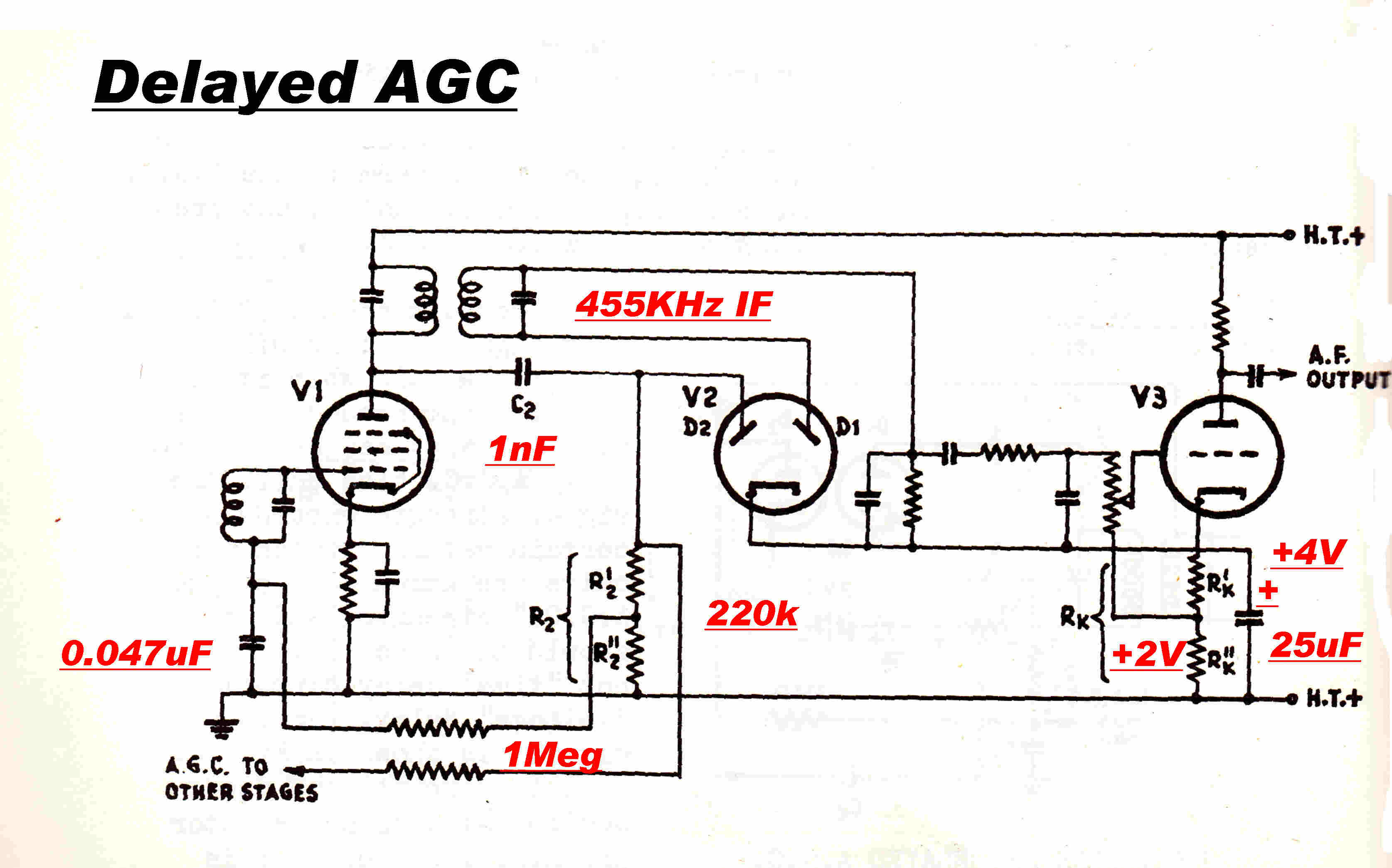 The dynamics and mechanisms for distortion generation
in AGC loops are extensively covered in the Tuner and Airzone sections.
In low priced receivers the negative AGC voltage is derived from the
diode detector. The voltage stored on the filter capacitors in the AGC
line adds to the hold off voltage of the audio AC coupling and increases
the clipping on negative modulation.
A better arrangement is to use a separate diode for AGC generation.
This is usually biased so that AGC generation does not start until the
carrier level reaches a predetermined level - usually about three or four volts.
This puts a non-linear load on the output of the IF amplifier and
causes distortion.
In well designed receivers the impedance level of the AGC diode rectifier
is designed to be much higher than the detector impedance, so that the variable
loading has less effect.
In the Breville the AGC load is R14 1Meg and the detector load is R15 30k.
In the Airzone the primary of the output IF is wound with resistance wire
to increase the bandwidth. This also decreases the driving point impedance
and so the distortion caused by non - linear loading.
The simple AGC system copes well with local signals with ground wave propagation
and high signal level stability.
It is not adequate for the fading encountered in broadcast band or short wave
sky wave propagation.
These required amplified AGC and at least one extra tube - usually confined
to communication receivers.
A mono FM service was started in Brisbane on 6th October 1953 from a transmitter
situated at Mirrimbul on Mt.Cootha with a power of 1KW on a frequency of 91.1 MHz.
and horizontal polarisation.
The peak deviation was +(-)75KHz and the transmitter shared programs with the 4QR transmitter
via landlines equalised to 15KHz.
The transmitter was designed and manufactured by Radio Engineering Laboratories of New York
with whom Armstrong had formed a partership to fight Sarnoff at RCA.
It is not surprising, then, that the transmitter used Armstrong's original method of
producing frequency modulation -- phase modulation followed by 12 frequency
multipliers -- rather than RCA's direct modulation of an LC oscillator.
In an FM transmitter the frequency is not stable but deviates either
side of carrier. One of the earliest difficulties in designing an FM transmitter
was to achieve Xtal stability of the carrier frequency with no audio input.
Two approaches were possible:-
[1] Frequency modulation is the integral of phase modulation So :-
Phase modulate the frequency stable output of a Xtal oscillator with the integral
of the modulating signal.---Armstrong
[2] Frequency modulate an LC oscillator directly - compare its output with a Xtal oscillator
and correct slow frequency drift with a slow speed feedback loop which does not
attack the modulation, but only the drift.---RCA
The difficulty with the Armstrong method is that the phase modulation
possible with conventional tubes is totally inadequate and the signal must be frequency
multiplied a large number of times to achieve the required deviation on
low modulating frequencies - 12 times is typical.
Note: GE developed a special tube -The Phasitron Type: GL-2H21 or GL5593 - to produce larger
reasonably linear phase shifts. A brief account is given below.
The two conventional methods to produce phase modulation are:-
[1] Delay a short pulse from the start to the end of a cycle with a delay
linearly related to the modulating signal.
The maximum deviation is +(-) 180 degrees.
[2] Produce suppressed carrier AM in a balanced modulator and add this to a
carrier phase shifted by 90 degrees.
If the peak carrier output from the balanced modulator is Ab and the peak of the
phase shifted carrier is Ac, then the phase deviation
φ is given by:-
φ = tan-1( Ab/Ac )
However, for no distortion, a linear law is required:-
φ = ( Ab/Ac )
The initial phase deviation must be limited so that:-
φ ≈ tan( φ )
This indicates that the initial phase modulation at, say, 20Hz. is less
than 45 degrees. As the drive from the integrator decreases with
frequency, so does the distortion.
The block diagram for a typical Armstrong FM transmitter is
shown below.
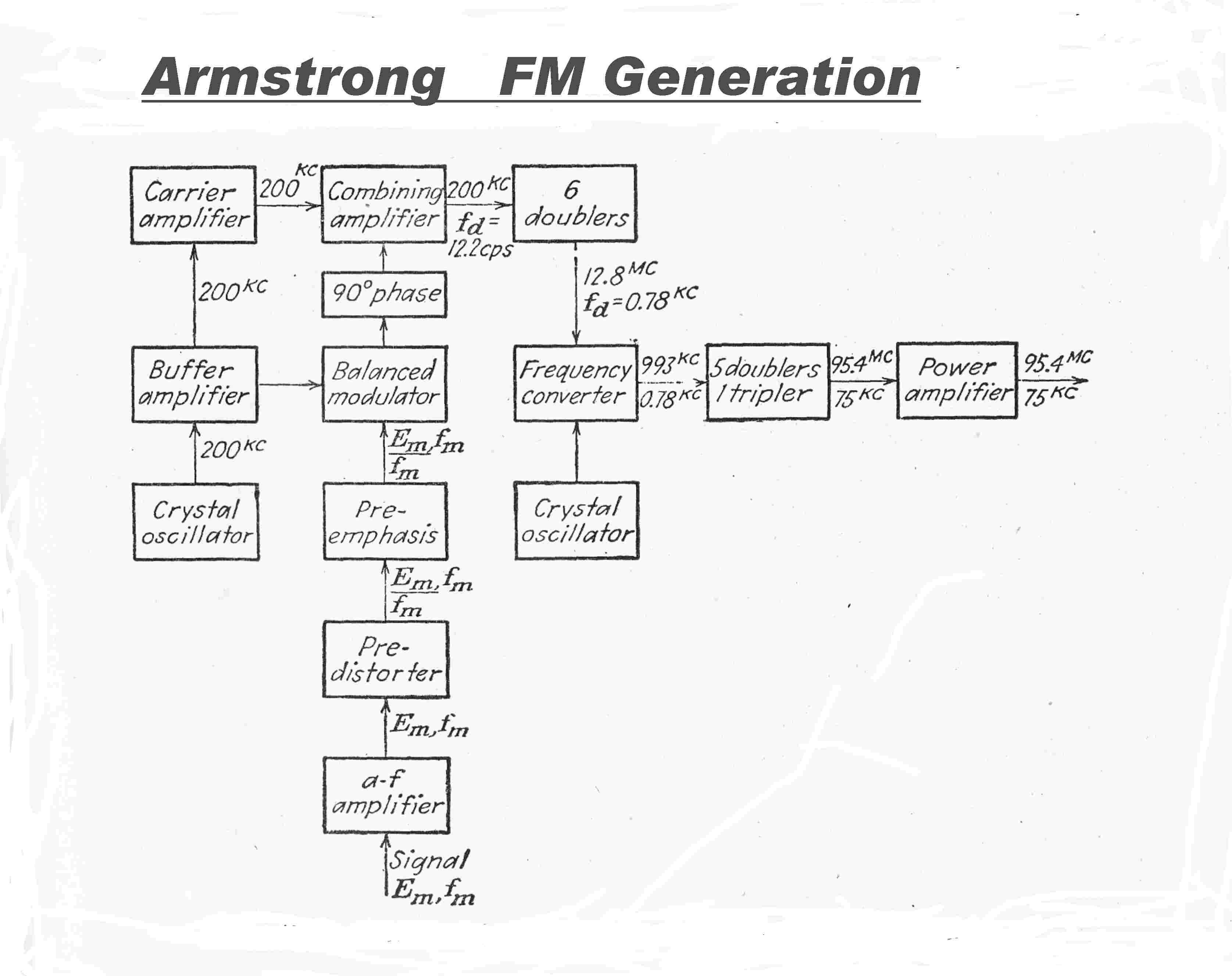
Let the frequency deviation be Δω
Then Δω = ωDsin( ωM t ) where:-
ωD = peak deviation and ωM is the
modulating frequency.
The peak phase deviation φ will occur over a quarter of a cycle T/4
of modulation
φ = ∫ ωDsin( ωM t ) dt
between the limits 0 and T/4
Since T = 2 Π / ωM --- then
T/4 = Π / ( 2 ωM)
So that φ = ∫ ωDsin( ωM t ) dt
between the limits 0 and Π / ( 2 ωM)
Integrating: φ = ωD [ ( -1/ωM) cos( ωM) t )]
0Π / ( 2 ωM)
OR
φ = [ ωD / ωM)]
[ -cos( Π ωM /2 ωM) + cos(0) ]
OR
φ = [ ωD / ωM)]
[ -cos( Π/2 ) + 1 ]
φ = ωD / ωM
= 2 Π fD / 2 Π fM
If the peak deviation is 75KHz and the lowest modulating frequency is 20 Hz,
then the peak phase deviation φmax is given by:-
φmax = 75 103 / 20 = 3.75 103 radians.
If a fair amount of low frequency distortion is tolerated and an initial phase
shift of 45 degrees is adopted, then the carrier frequency must be
multiplied by M :-
45 degrees = Π/4 = 0.7854 radians
M = 3.75 103 / 0.7854 = 4.7746 103
If the frequency multiplication in each of the n stages is 2 then we have
2n = 4.7746 103
n = 12.2
So we need about 12 or 13 stages of frequency multiplication.
Now 26 = 64, so, after about 6 stages the frequency is getting high.
The solution is to use the output from another Xtal oscillator to convert down to
some low frequency and start the multiplication process over again.
From the above it can be seen that there were two sources of distortion
in the transmitter:-
[A] Low frequency distortion due to the phase modulation process.
[B] High frequency distortion. Each frequency multiplier has its own
bandwidth limited coupling circuit. This can cause distortion to
high frequency modulation.
The vacuum tube FM transmitter has one enormous advantage over its AM counterpart -
the modulation process is inherently at low level and all RF amplifiers run
at near saturation and so high efficiency - the linearity of these amplifiers
is of no consequence.
AM transmitters using the AMPLIPHASE system go part way to redress the balance.
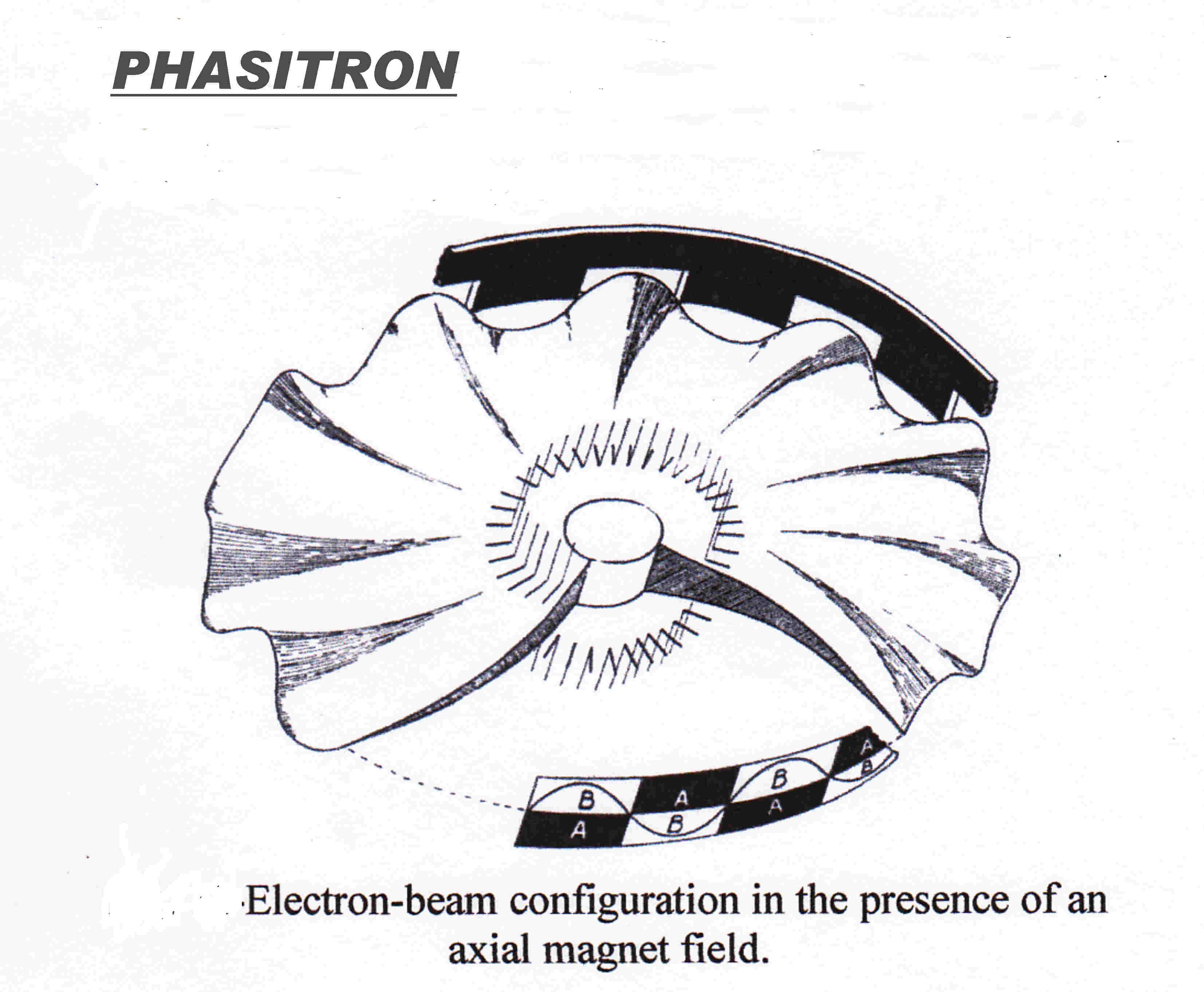 GE developed a special tube - named The Phasitron - to achieve much
greater phase modulation with reasonable linearity.
This was not used in the first Brisbane FM transmitter.
This web site is devoted to vacuum tube techniques - so it will be described.
Imagine a circular cathode surrounded by a circular anode such as in a magnetron.
Electrons emitted from the cathode travel along a radius directly to the anode.
if a magnetic field is applied at right angles to the electron flow a circular orbit
results and the point of arrival or phase of the electrons is changed.
The deflection or phase change is a linear function of the magnetic field strength.
If the magnetic field varies with the FM modulating signal, the phase or point of
arrival will correspond to the required phase modulation.
Some marker is required on the electrn disc to denote its angular deflection.
This is achieved with three independent electrostatic deflection systems which
deflect the electron stream along the direction of the cathode
parallel to the magnetic field.
These are driven from a three phase signal at Xtal frequency.This rotates the
deformation at that frequency.
The modulated magnetic field adds to or subtracts from the rotation.
Holes are placed in the anode so that the rotating electron stream produces
an externalpulse and hence aphase phase modulated signal as it passes the hole.
The shape of the rotating electron stream is shown opposite.
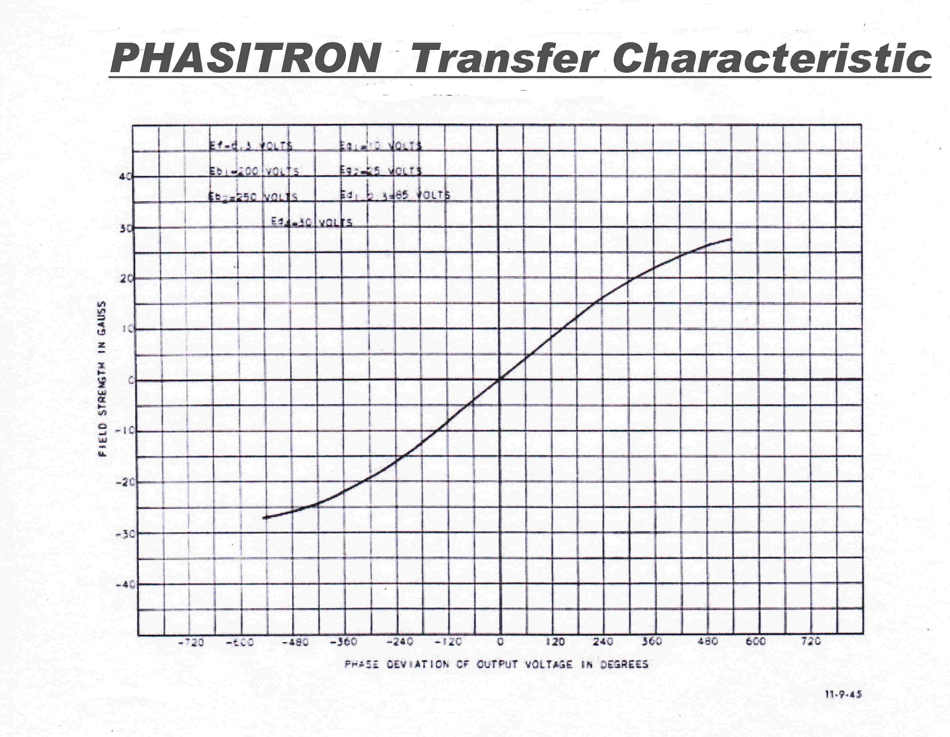 The transfer characteristic of the Phasitron
[ deflection angle / transverse flux density ] is shown opposite.
It is noteworthy that the phase modulation is reasonably linear only within
the range +(-) 180 degrees. Beyond that significant even order
harmonic distortion occurs : far more than can be tolerated in any
high fidelity broadcast system - FM or AM.
The GE tube manual gives a distortion of 1.4% at +(-)180 degrees -
not an impressive figure!
A better result can be achieved with pulse techniques using a couple
of conventional tubes : say the 6AC7 pentode and the 6J6 or 12AT7
double triode.
[1] Produce a linear ramp for the duration of each cycle of carrier.
[2] Produce a short pulse at the intersection of the ramp and
the modulating voltage.
[3] Drive a wideband tuned circuit centered at carrier frequency with
the short pulse.
[4] A sinusoid with +(-) 180 degreee linear phase modulation results.
Pulse techniques were ignored in favour of CW techniques all too often -
a case in point being the phase modulator for the early Ampliphase
transmitters.
It is difficult to understand the philosophy behind the design of
the Phasitron.
The peak flux density required for full modulation is only about
20 gauss - a small field which requires mu-metal shielding from
external fields.
In the GE transmitter design the current - voltage relationship in
the inductor formed part of the integration process.
A very high impedance inductor with many turns and voltage driven
was chosen. This was unfortunate, for the self- capacity of the coil
limited the high frequency response.
The system was not responsive to the high frequency subcarrier
in stereo transmissions.
There is no inherent frequency limitation in the Phasitron.
A better understanding of the operation of the
Phasitron may be had from the sectioned drawing below:-
For more details on the design of the Phasitron see:-
A New System of Frequency Modulation by Robert Adler
Proc. IRE Jan 1947.
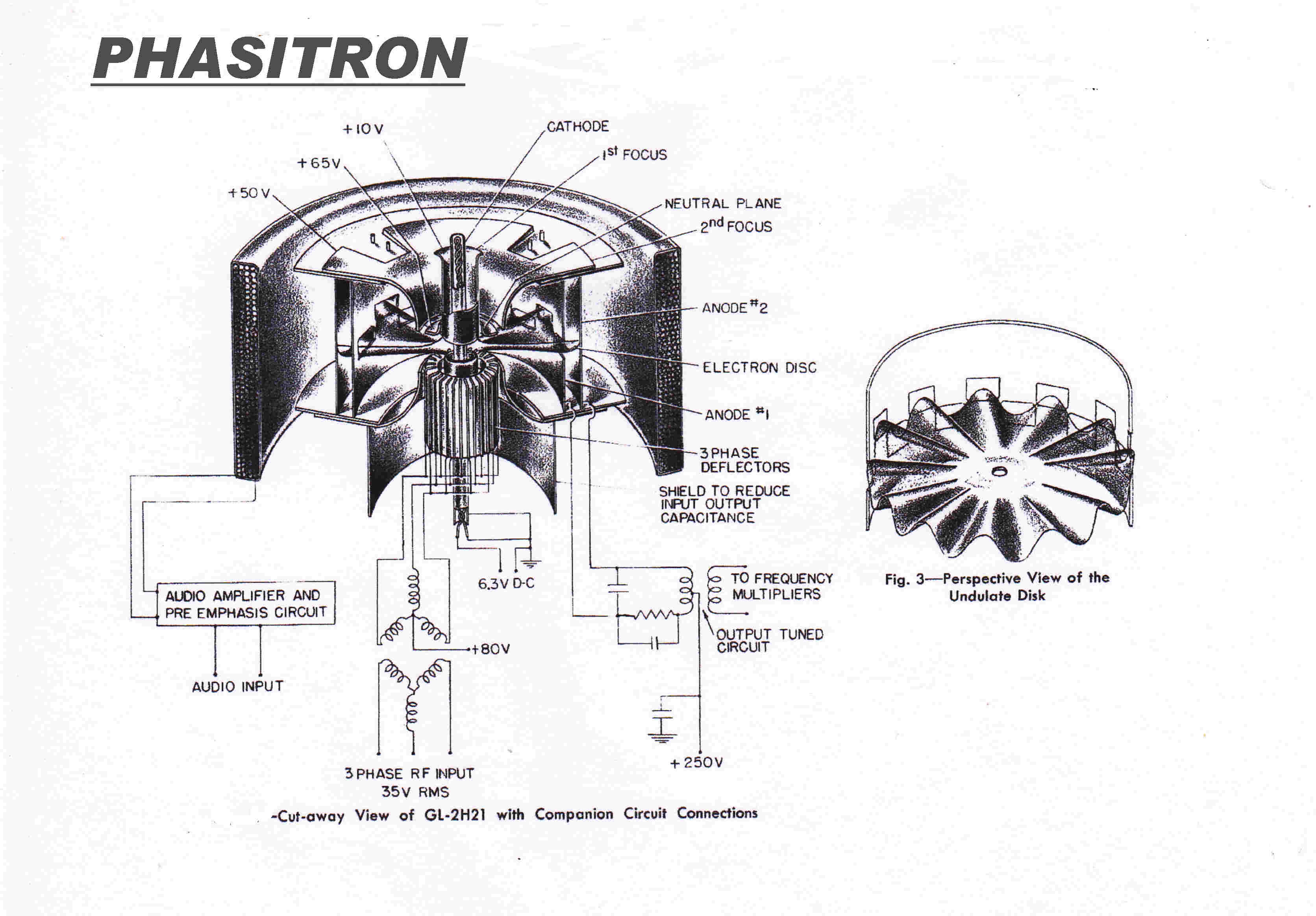
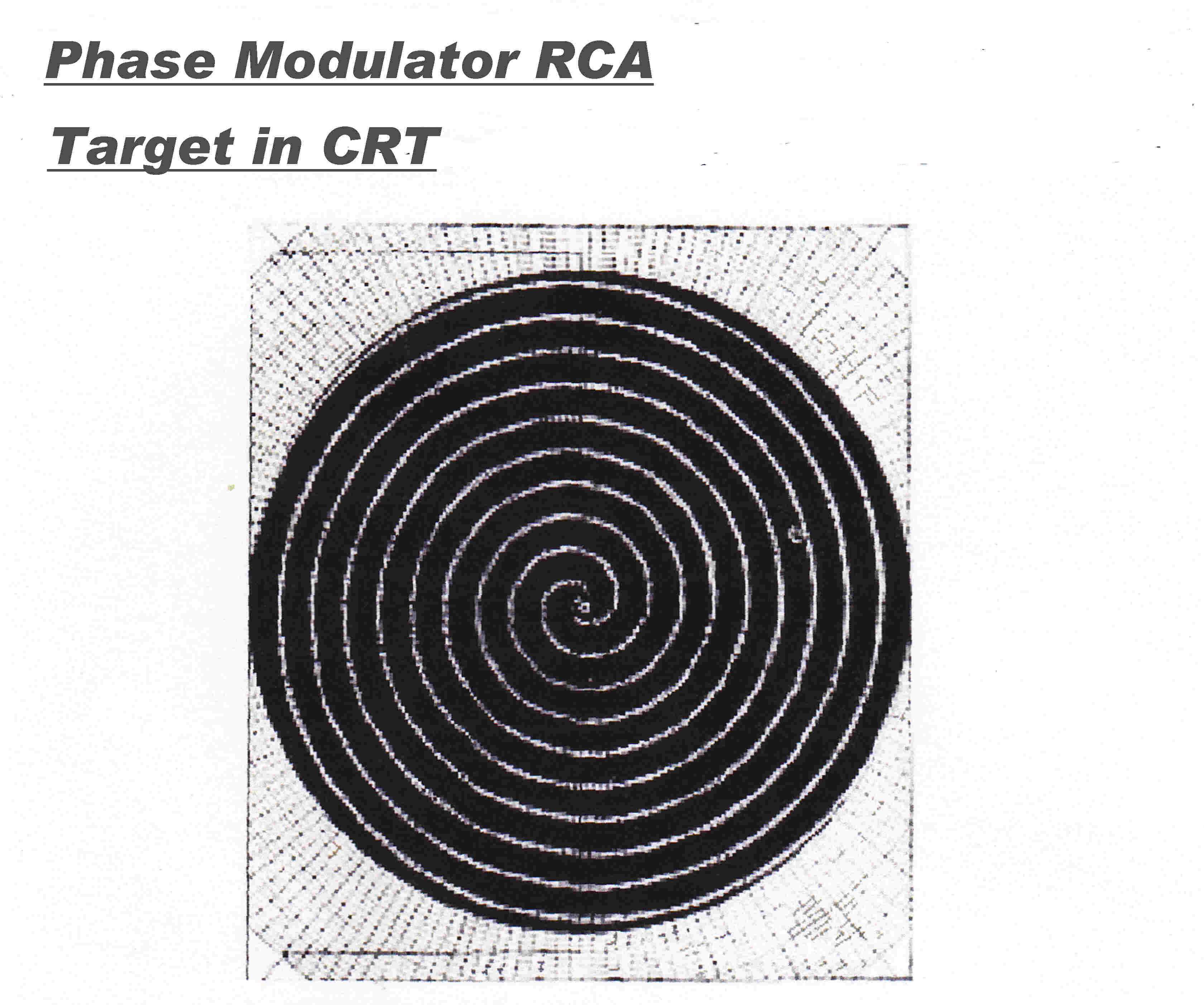 RCA developed a special tube which was capable of much greater
phase deviation and better linearity than the Phasitron.
The principle is rather similar to that found in the Phasitron, but the
realisation very different.
Imagine a thin conducting surface sputtered onto a sheet of mica.
Inscribe two intertwined Archimedian spirals onto the surface.
Let this replace the normal CRT phosphor screen.
If the electron beam is deflected in a circle, a square wave of current
will flow from the two electrodes at the deflection frequency.
As the radius of the circular deflection is increased, the phase of the
square wave changes because the intersection point changes.
Now the polar equation for an Archimedian spiral is :-
R = k Θ where R is the radius; k a consant and Θ the deflection angle
so the angular change in the output square wave is a linear function of
the radius of the deflection.
In practice it was possible to produce targets with a 5 x 360 degree deviation
with excellent linearity.
A fully modulated AM sine wave and its cosine counterpart are applied to the
X and Y deflection plates to give a modulated circular trace.
Linear phase modulation of +(-) 5 x 360 degrees results.
The surface of the target was covered with Willemite to give a visual
indication of the action and ease of setup.
Three other all vacuum tube FM transmitters were installed in Brisbane in 1959.
They formed the FM sound channel in TV transmitters.
All used direct modulation.
The first, an RCA TT-11AH, directly modulated an L-C oscillator.
In the receivers the inter-sound carrier frequency was obtained as the difference between
the vision and sound carriers. The RCA transmitter stabilised this frequency to Xtal accuracy -
excellent pactice.
In the other two transmitters, an attempt was made to frequency modulate directly a Xtal oscillator -
an immovable object and an irrestible force! No attempt was made to stabilise the difference
between the two carriers - nor was any other attempt at centre frequency stabilisation.
For a further discussion see below.
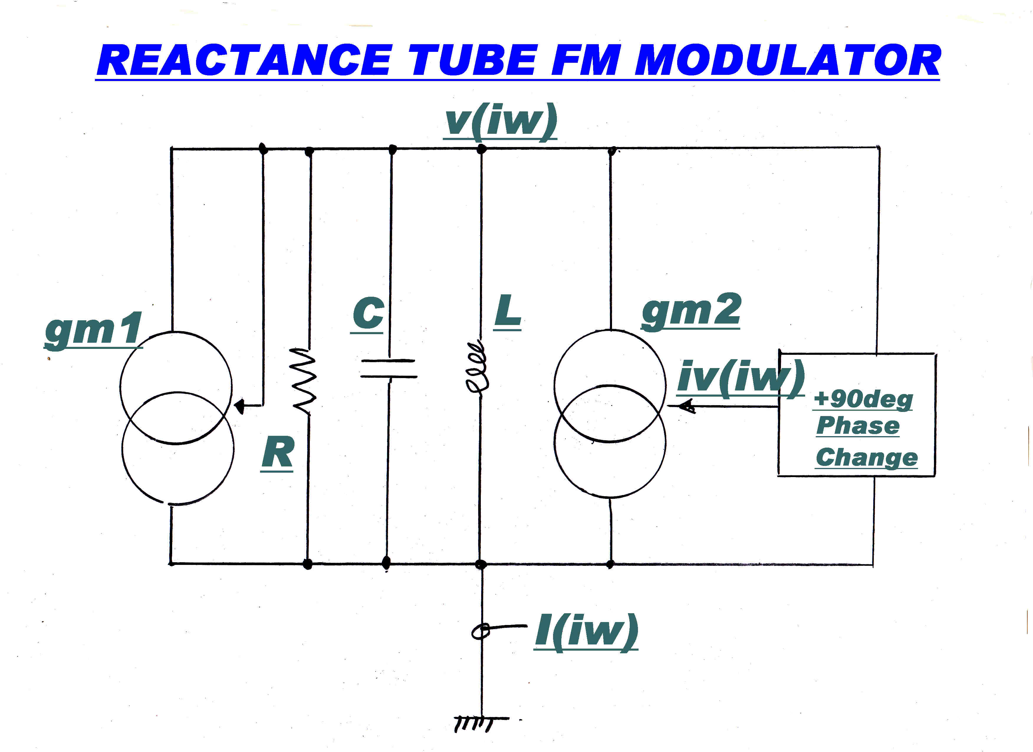 Direct FM modulation of an L-C oscillator by a reactance tube modulator can be
accomplished with minimal distortion.
The difficulty is then stabilising the centre frequency to xtal standard.
The basic circuit of a reactance tube modulator is shown opposite.
The current generator gm1 = -1/R to maintain constant amplitude oscillation.
The phase of the output voltage v(i ω) is shifted by 90 degrees and applied
to the input of the current generator gm2 producing an output
current
Iout(i ω) = i ω v(i ω) gm2.
The current generator will then appear as a pure susceptance y(i ω) where
y(i ω) = Iout(i ω)/v(i ω)
= [ i ω v(i ω) gm2]/v(i ω) = [ i ω gm2]
If we vary gm2 wth audio modulation, the resonant frequency of the L-C tuned circuit will
also vary.
This can be expressed algebraically as follows:-
I(i ω) = v(i ω)[ gm1 + 1/R + iωC -i/ωL + iωgm2 ]
For constant amplitude oscillation: gm1 = -1/R so:-
I(i ω) = v(i ω)[ iωC -i/ωL + iωgm2 ]
At the oscillating frequency ω , I(i ω) = 0 so:-
iωC -i/ωL + iωgm2 = 0
Then ω = 1/[ (L C)1/2 ( 1 + gm2/C)1/2 ]
ω = [ ( 1 + gm2/C) -1/2 ]/[ (L C)1/2 ]
Now gm2/C << 1 , so we expand with the binomial theorem
ω = [ 1/ (L C)1/2 ] [ 1 - 1/2gm2/C + (-1/2)(-1/2 - 1 ) (gm2/C)2/2 /2! ------------ ]
ω ≈ [ 1/ (L C)1/2 ] [ 1 - 1/2gm2/C + (-1/4)(-1/2 - 1 ) (gm2/C)2/ ]
ω ≈ [ 1/ (L C)1/2 ] [ 1 - 1/2gm2/C + (0.375 ) (gm2/C)2/ ]
For a balanced modulator, gm2 = k M(t) where M(t) is the modulating signal.
f ≈ [1/2 Π] [ 1/ (L C)1/2 ][ 1 - k/2C M(t) + 0.375 ( kM(t)/C )2 ]
Put M(t) = sin( ωm t ) then :-
f ≈ [1/2 Π] [ 1/ (L C)1/2 ][ 1 - k/2C sin( ωm t ) + 0.375 ( ksin( ωm t )/C )2 ]
f ≈ [1/2 Π] [ 1/ (L C)1/2 ][ 1 - k/2C sin( ωm t ) + 0.375 ( k/2C )2 (1/2)( 1 - cos(2 ωm t)) ]
f ≈ [1/2 Π] [ 1/ (L C)1/2 ][ 1 + 0.75 (k/2C)2 - (k/2C) sin(ωm t) - 0.75(k/2C)2cos(2 ωm t)]
Now [1/2 Π] [ 1/ (L C)1/2] = fo where fo is the carrier frequency
Put k/2C = δ The equation becomes:-
f ≈ fo[ 1 + 0.75 δ2 - δsin(ωm t) - 0.75 δ2cos(2 ωm t )]
Put the peak deviation at the fundamentral modulating frequency = Δf = foδ
So δ = Δf/fo
For Δf = 75KHz : fo = 100MHz δ = 7.5x 10⁻⁴
The fractional second harmonic distortion = 0.75 δ2/δ = 0.75δ = 5.625 x 10⁻⁵
The carrier shift = 0.75 x 10⁻⁷δ2 = 42Hz
CONCLUSION:THE DISTORTION DEPENDS ESSENTIALLY ON THE (LINEAR) RELATIONSHIP BETWEEN THE gm AND GRID VOLTAGE
OF THE REACTANCE TUBE.
COMMENT ON FM CALCULATIONS
[1] FM modulation is denoted by INSTANTANEOUS FREQUENCY, yet the above calculations were done using steady state
frequency. The two converge as the rate of change of the modulating signal approaches 0.
The analysis, then. can be trusted only for low modulating frequencies.
Only in steady state can we write the susceptance of a condenser y = i ω C
[2] The Q of the tuned circuit is very high - virtually infinite to give continuous oscillation - so if the bandwidth is very low,
Is the FM instantaneous? It is. Normal steady state circuit ideas do not apply, for in it the assumption is that all passive
elements are constant. Here this is not so - gm varies with time.
Instantaneous frequency is discussed more fully in THE INTRODUCTION.
See Introduction
FM MODULATION LINEARITY - Gm versus grid voltage
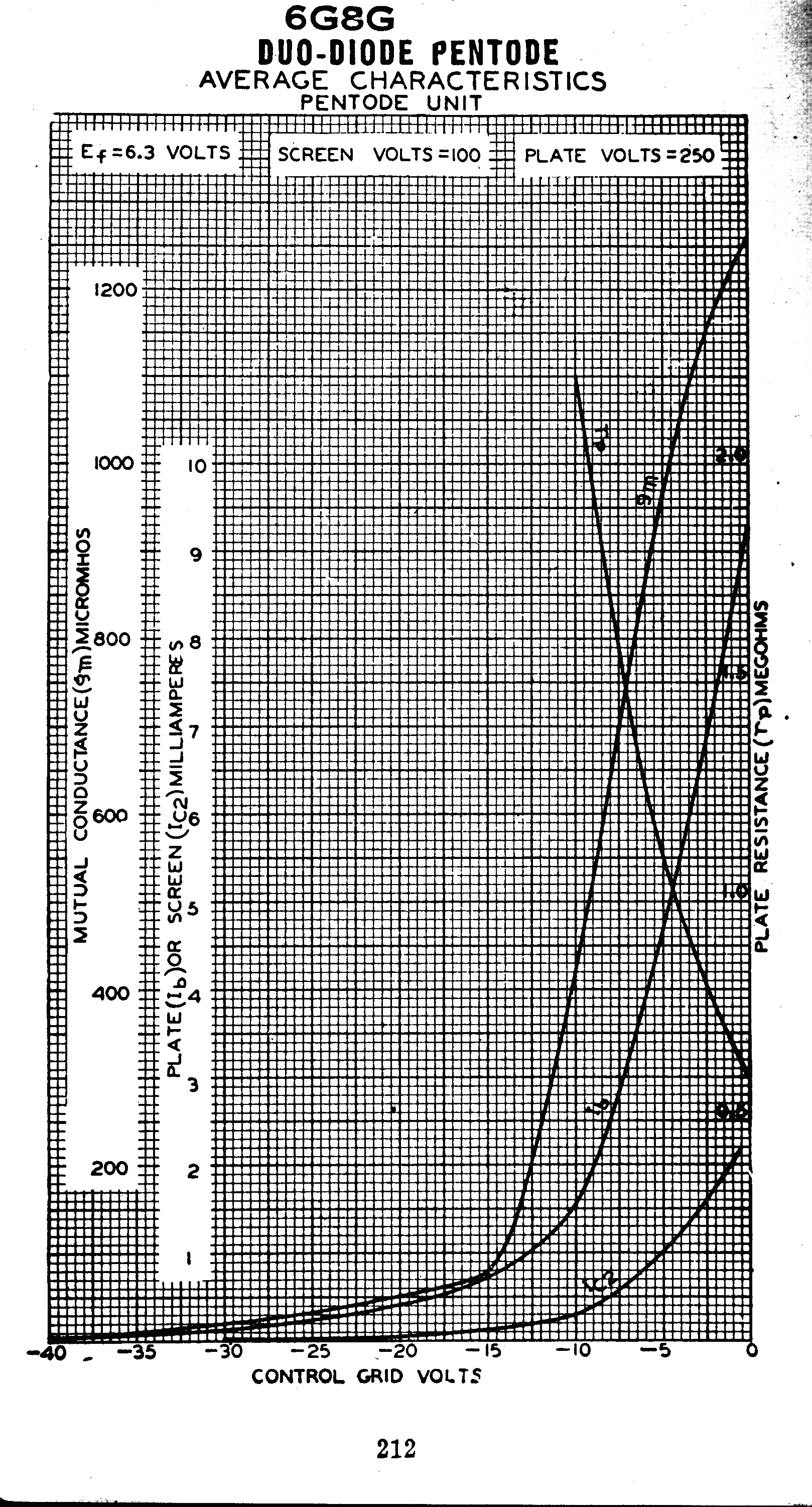 The algebraic analysis indicates that the modulation linearity is entirely dependent
on the relationship between the gm of the reactance tube and the grid voltage.
If this is linear, then the there will be no distortion in the modulator.
If the three halves power law between plate current ip and grid voltage vg applies then:-
ip = k vg3/2
gm = dip/dvg = (3/2)k vg1/2 --not the required linear law.
It can be shown that AM modulation suffers no distortion passing through a square law transfer characteristic,
so this was designed into many tubes using "the inselbildung" effect.
The curves for an Australian RF pentode designed in the mid thirties shown opposite demonstrate this.
ip = k vg2
gm = dip/dvg = 2k vg
The law required for no distortion
For more detail on "Inselbildung" see:-
See 6L6 Amplifier
For more detail on Square Law see:-
See Tuner
The characteristics of three tubes suitable for reactance tube service are shown below:-
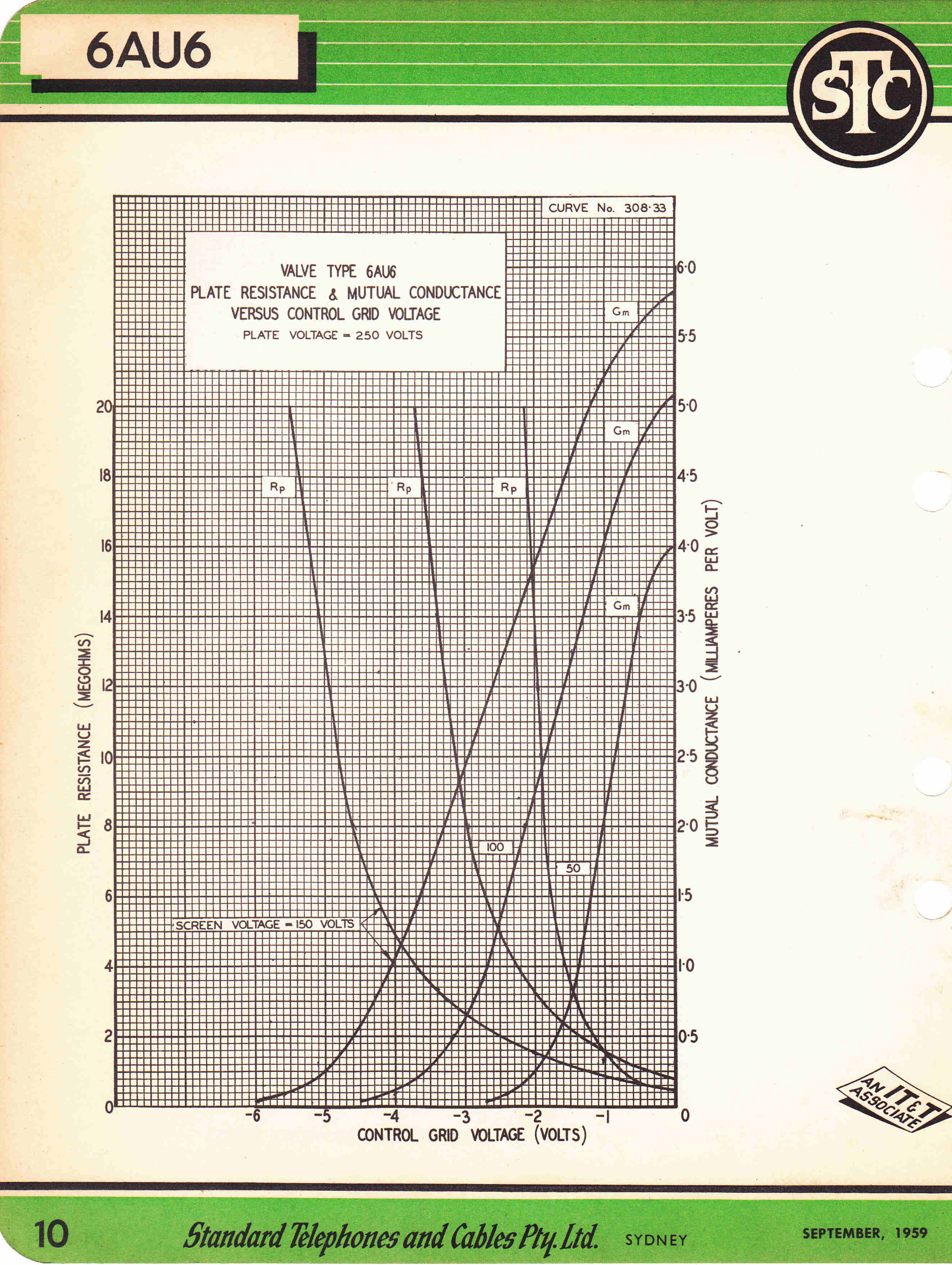
|
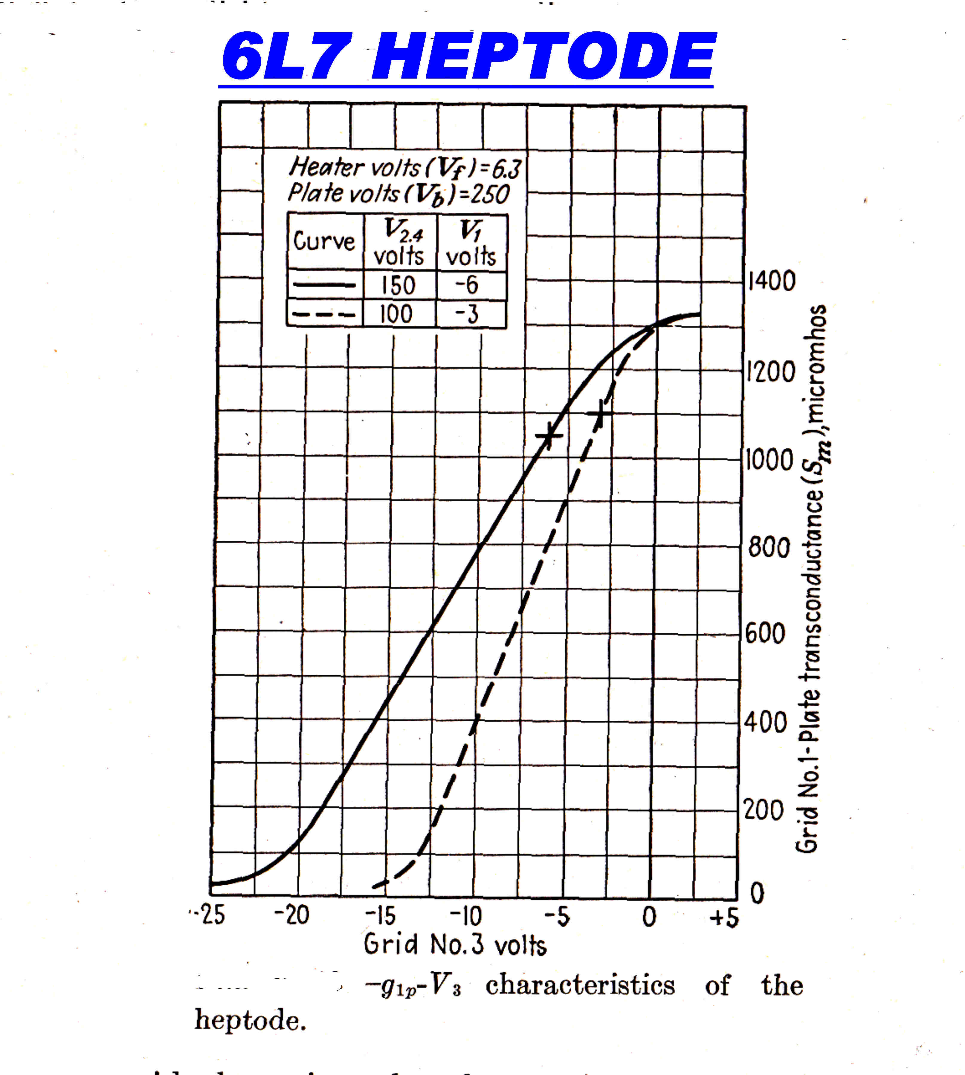
|
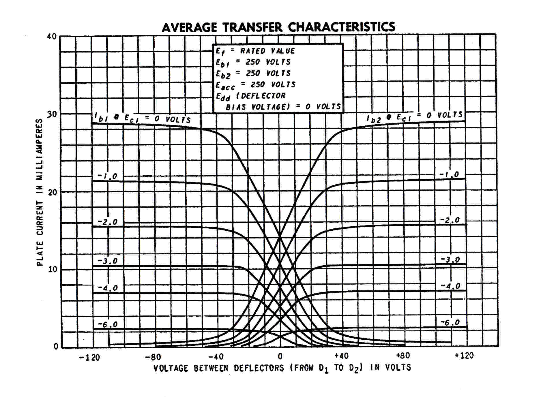
|
|
6AU6 MINIATURE RF PENTODE |
6L7 OCTAL HEPTODE 1937 |
BEAM DEFLECTION TUBE |
CIRCUITS OF REACTANCE TUBE MODULATORS

|
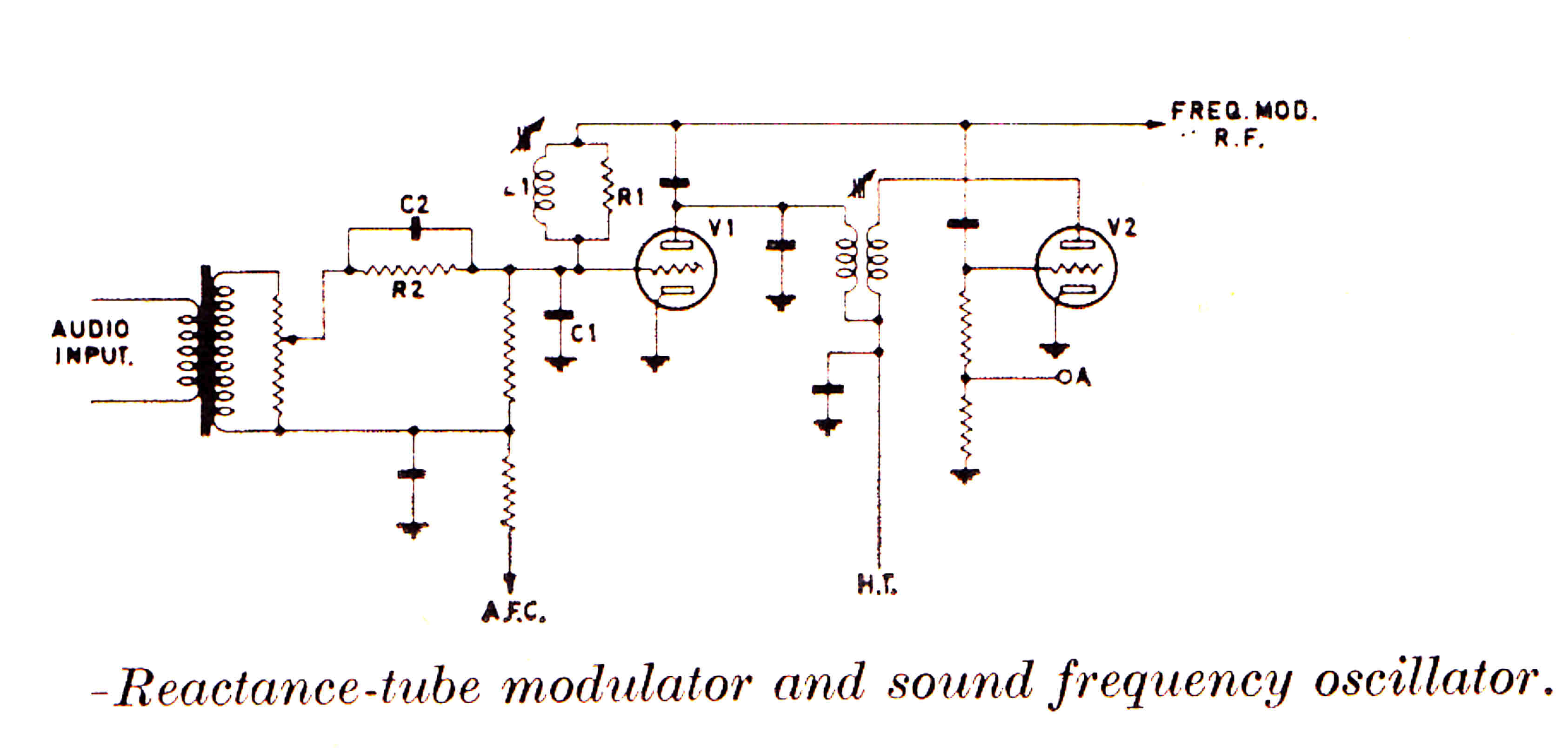
|
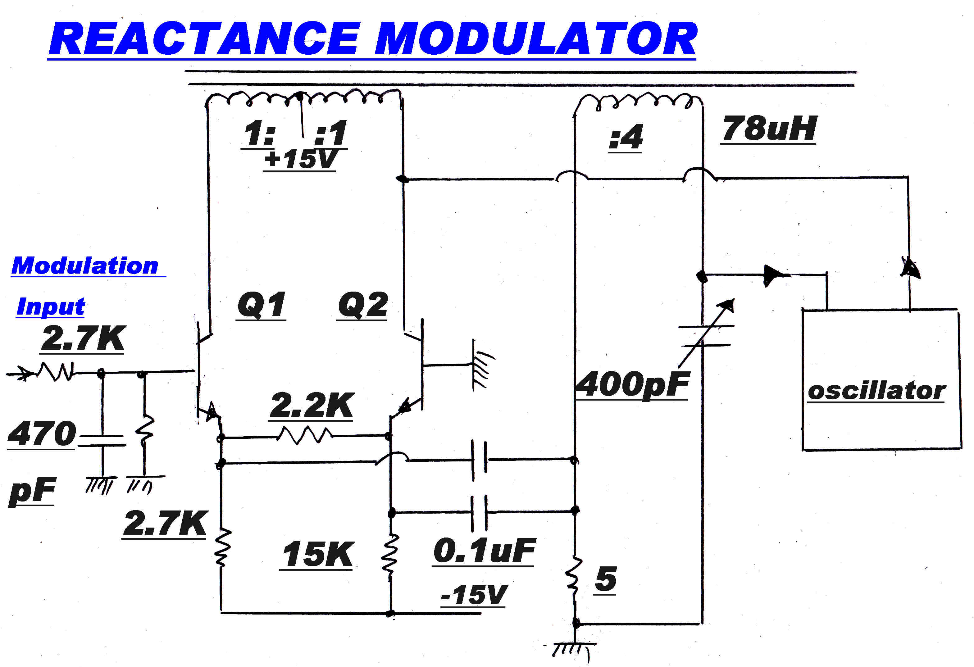
|
|
BALANCED MODULATOR |
FM MODULATOR -- RCA TT-11 AH |
SOLID STATE BALANCED MODULATOR |
FREQUENCY STABILISATION
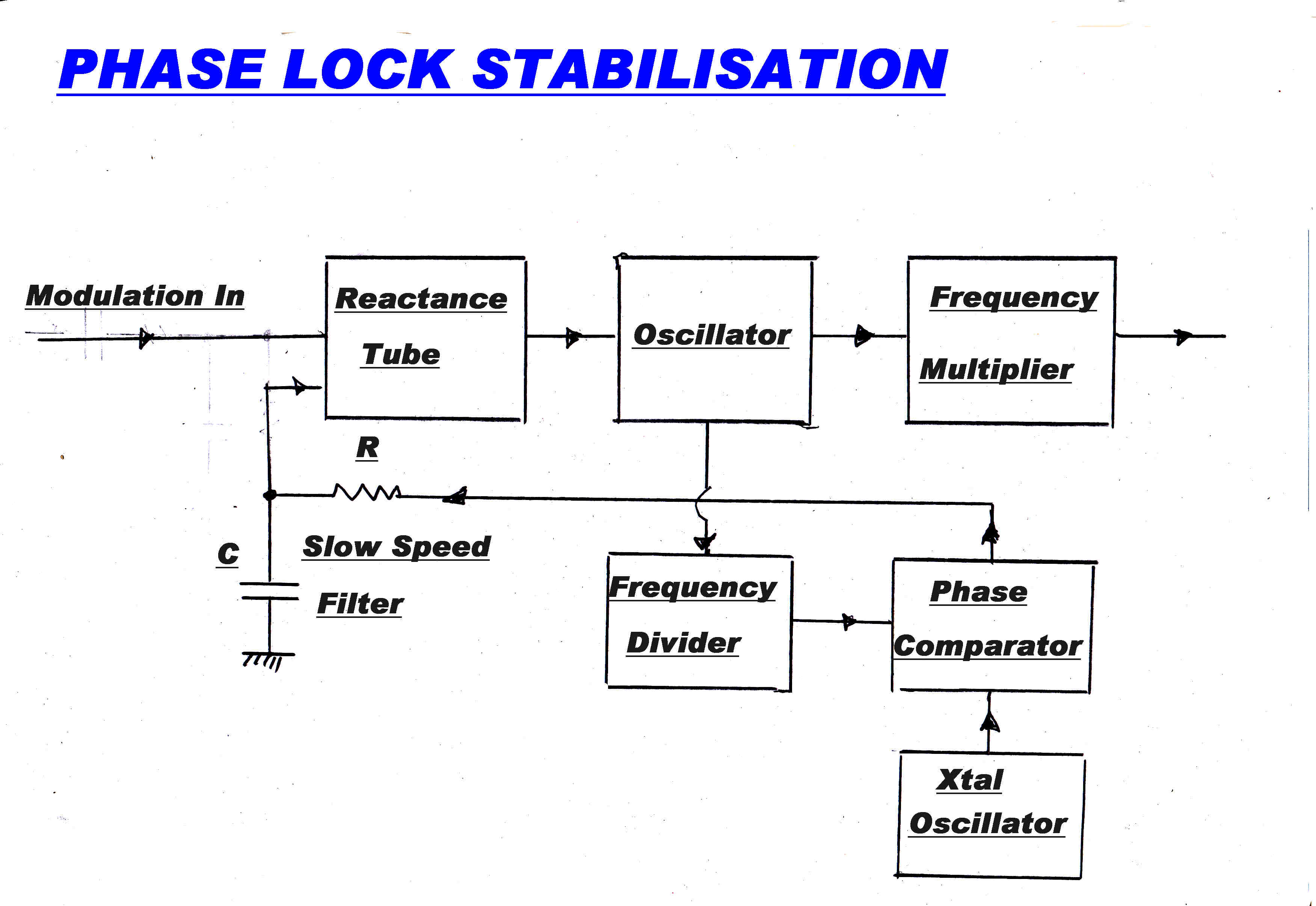 The ultimate goal to stabilise the centre frequency of an FM transmitter is
to phase lock it to a crystal oscillator.
This presents a major problem.
The phase deviation ( modulation index δ ) at low frequencies is of the order of 1000 radians, but most
vacuum tube phase detectors are only valid over a range of +(-) Π/4 radians, so the modulator output
must be divided down to be within this range.
Take the case of an FM transmmitter for TV.
The maximum deviation f = 50KHz.
Low frequency cutoff = 50Hz.
Modulation index δ = 5 x 10⁴/50 = 103 radians.
Typically, the frequency is multiplied X12 after the modulator, so the modulation index at the modulator is 1000/12 = 83.3 radians.
This must be divided down by N to give Π/4 radians.
N = ( 4/Π) x 83.3 = 111.
This frequency division is usually done by injection locked L-C oscillators - usually x4 or x5.
In general δ/N = Π/4 so:-
N = ( 4/Π ) δ
The basic scheme is shown opposite.
After filtering through an R- C low pass filter the error is DC coupled to the control grid of the reactance tube.
USUAL TOPOLOGY FOR FREQUENCY STABILISATION
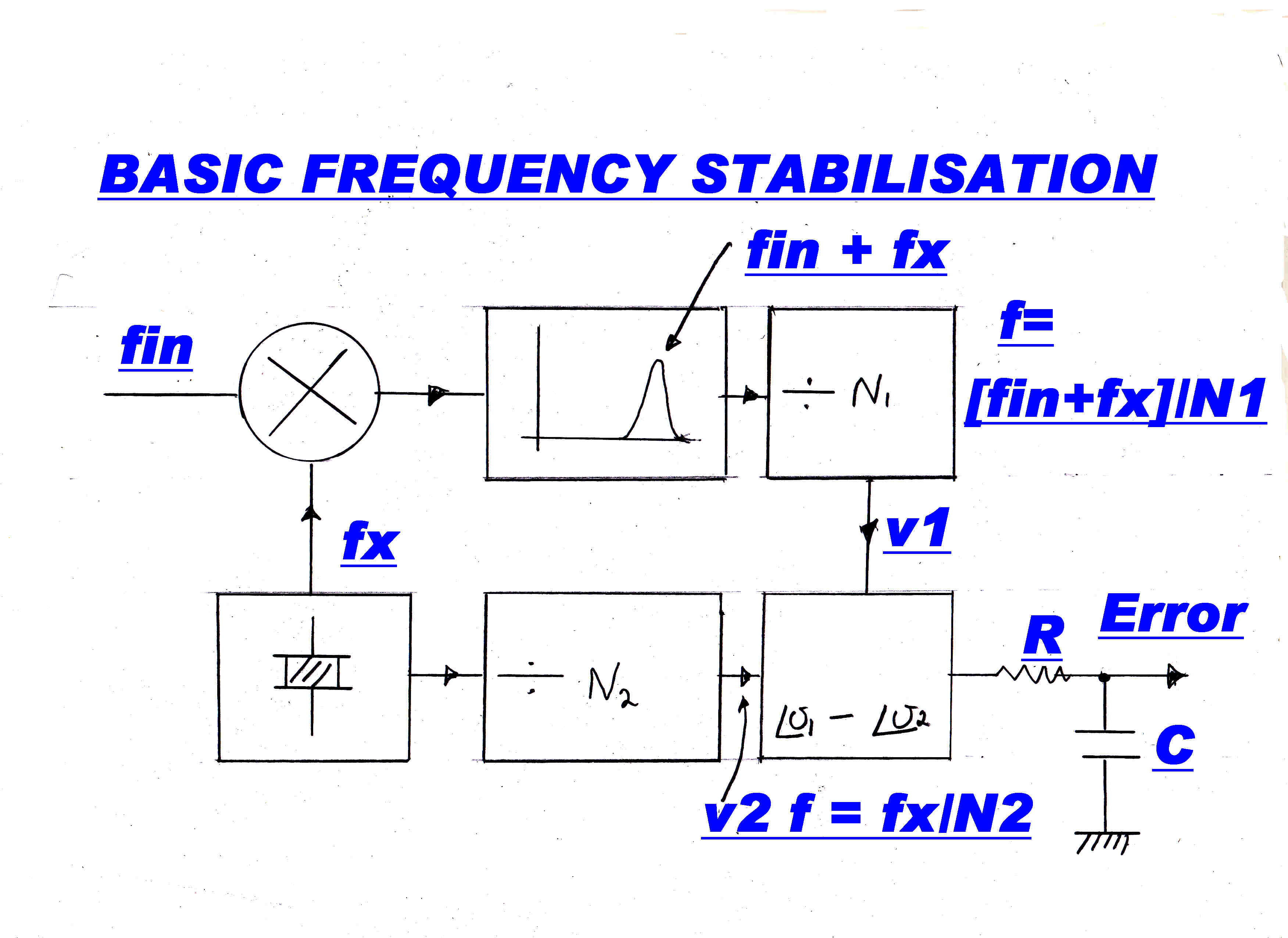 The usual topology for FM frequency stabilisation is shown opposite.
The Xtal frequency fx and input frequency fin are applied to a mixer.
The upper frequency ( fx + fin ) is filtered in a band pass filter and divided down by N1.
We have:-
fx/N2 = ( fx + fin )/N1
This gives:-
fin = ( N1/N2 - 1 ) fx
Usually N1 = 125 : N2 = 100 so:-
fin = 0.25 fx
EARLY DIRECT MODULATION FM TRANSMITTERS
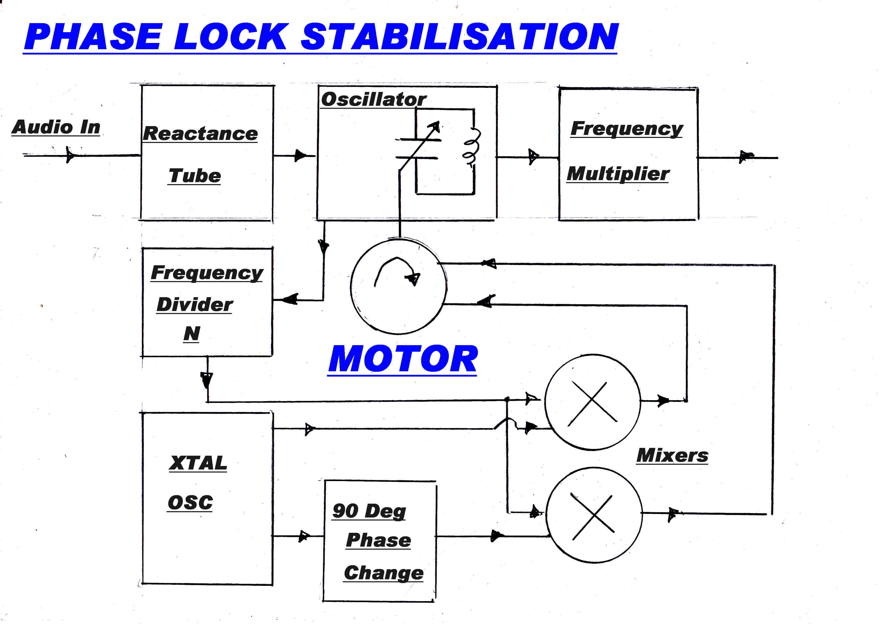 In early direct modulation FM transmitters, the vacuum tube phase detector was replaced by a motor
which drove the shaft of the main tuning capacitor directly.
The motor acted as both a frequency and phase discriminator.
Two outputs from the Xtal oscillator in quadrature were applied to two frequency changers to develop
quadrature drive for the motor.
Two advantages were claimed for the motor drive:-
[1] By changing the main tuning capacity, and not the working point of the reactance tube, optimum conditions
for linearity were maintained in the reactance tube.
[2] Drive failure would pobably stop the motor and leave it in the last adjusted position.
This system was developed by Murray G Crosby at RCA.
FM MODULATOR IN AWA TV TRANSMITTER
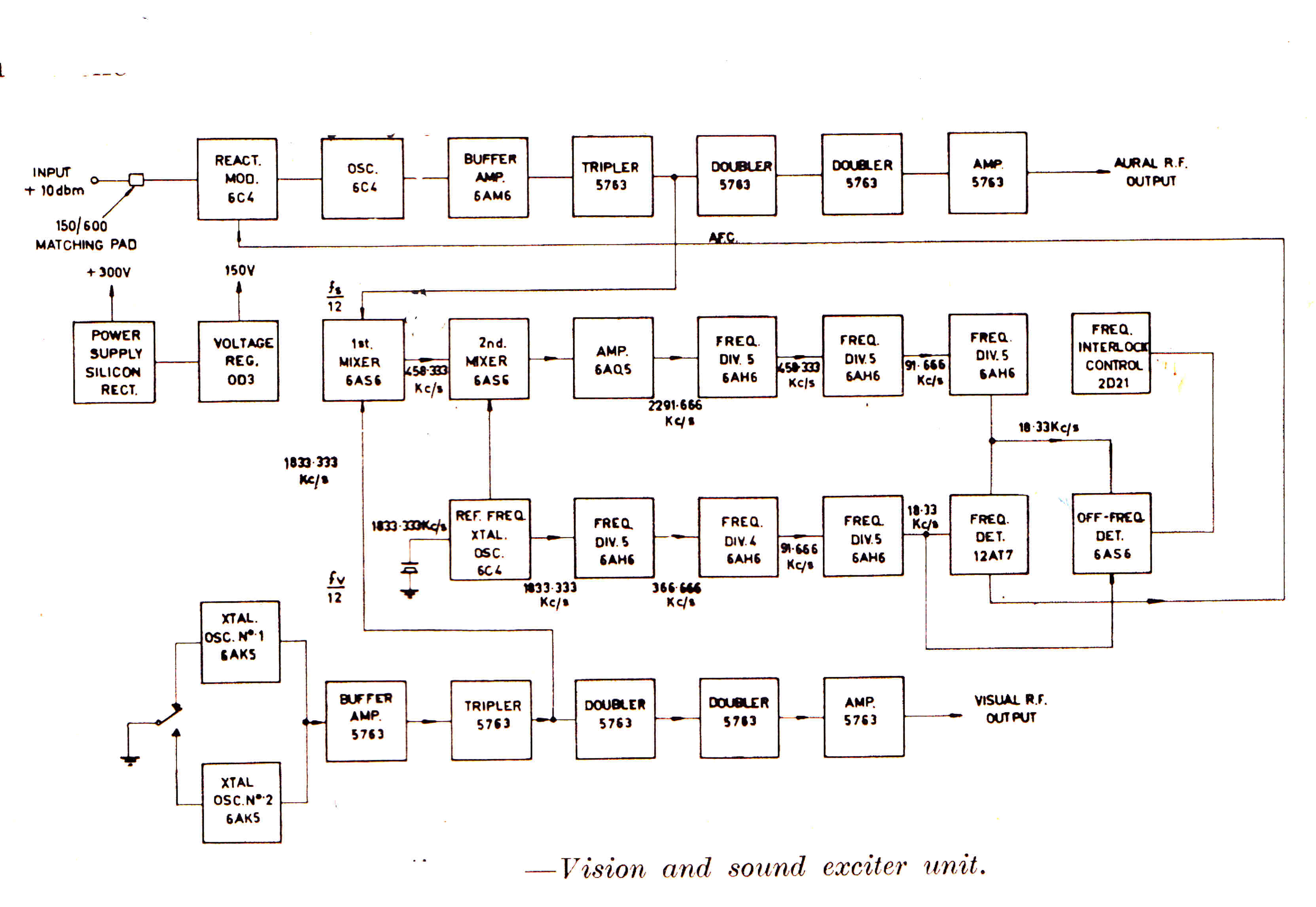
FM MODULATOR IN RCA TT-25DH TELEVISION TRANSMITTER
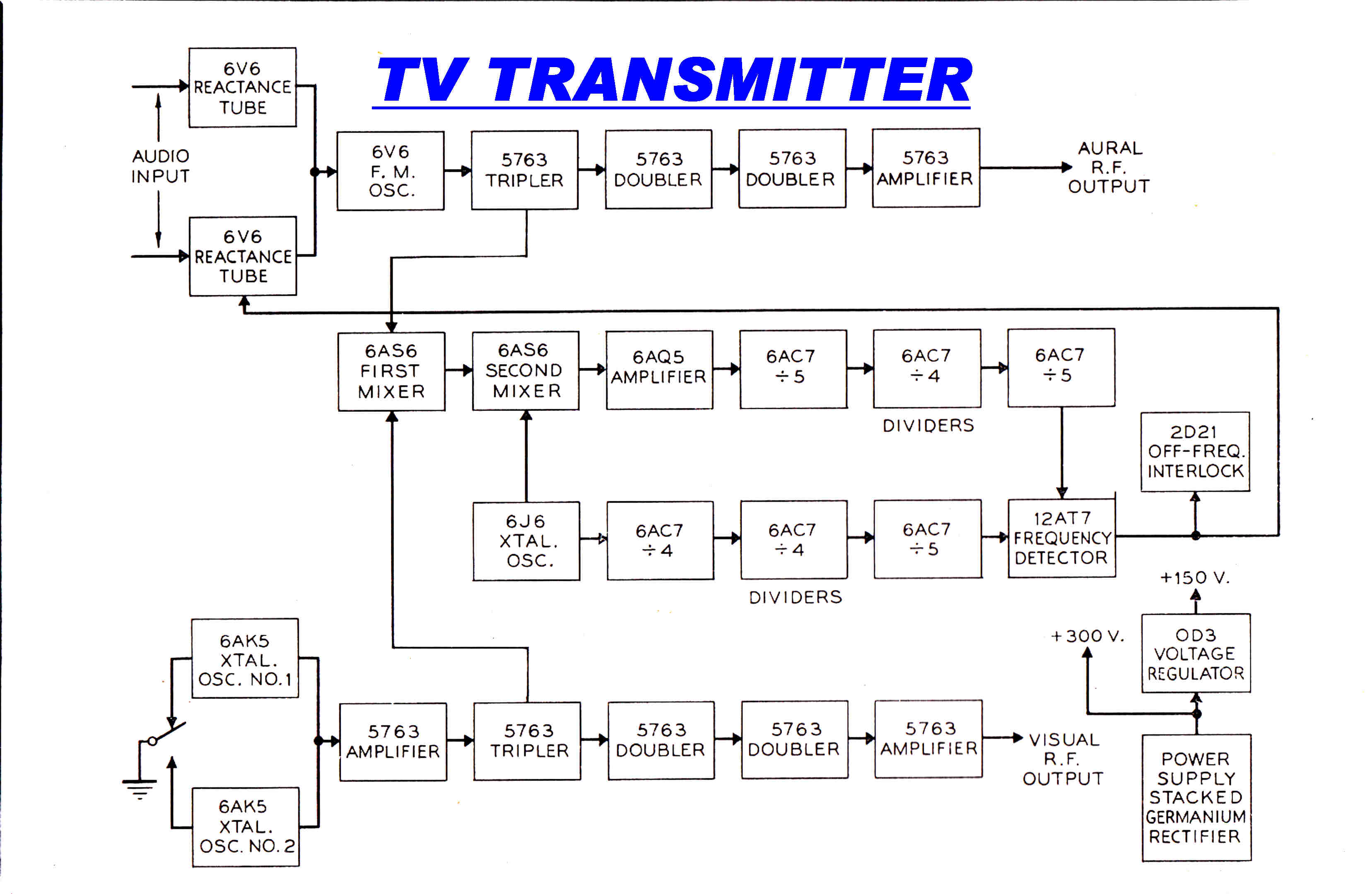
DIRECT MODULATION OF XTAL OSCILLATORS
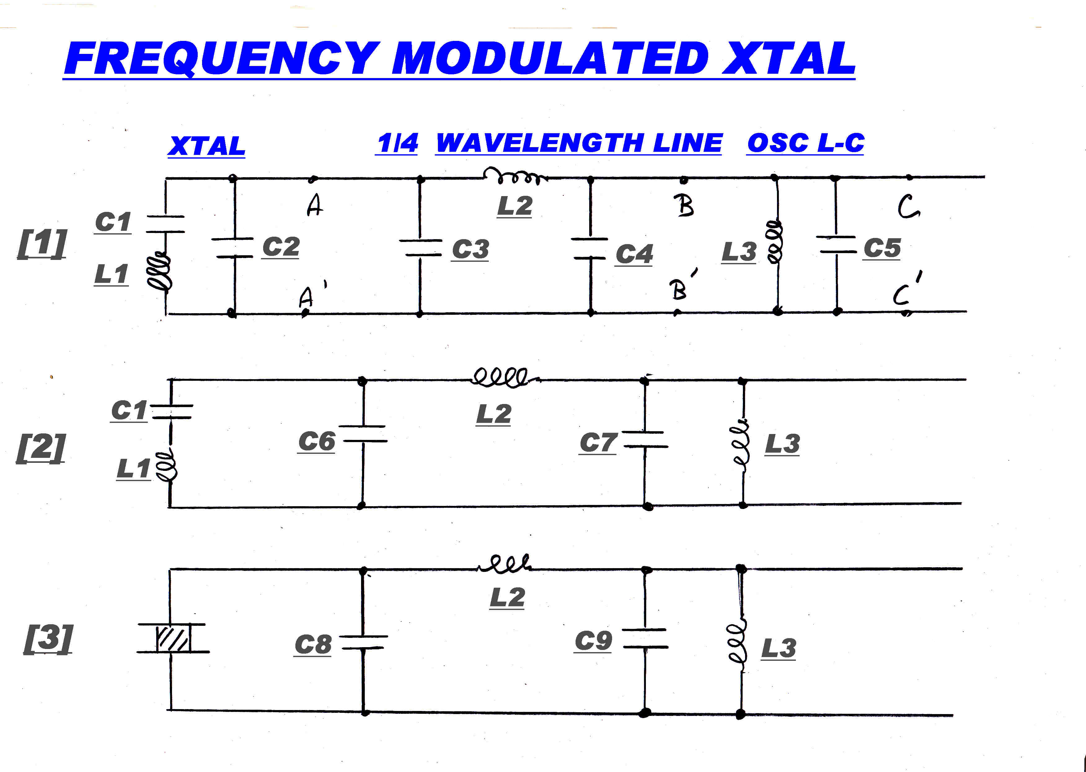 The basic scheme to directly modulate a Xtal oscillator is shown opposite.
A reactance tube operates on a parallel tuned circuit, so an L- C quarter wavelength line ( C3-L2-C4 )
transforms the Xtal series resonant circuit L1-C1 to a parallel resonant circuit across the parallel tuned circuit
of the oscillator L3 - C5
The parallel capacity of the Xtal is adsorbed into the capacity of the quarter wavelength line to give C6
The frequency of the L-C tuned circuit of the oscillator is stabilised, but any drift in the reactance tube modulator
appears directly in the output frequency.
Any attempt to reduce the drift in the reactance tube usually makes the anode current a linear function
of modulating voltage. Unfortunately this gives a gm law which causes gross distortion.
This is not so for bipolar transistors in which the gm is a linear function of collector voltage
for low currents.
For more detail on this Law see:-
See Tuner AGC
It has been pointed out above that almost all AM tuners
failed to realise the excellent potential performance of AM modulation
on the broadcast band.
Almost all FM tuners also failed to fullfill the promise of low distortion
FM narrow-casting.
The rather different circuit topology developed to correct this is
described below. Most FM tuners constructed by my students in the mid
to late fifties were based on these ideas.
The block diagram of the FM receiver is shown below:
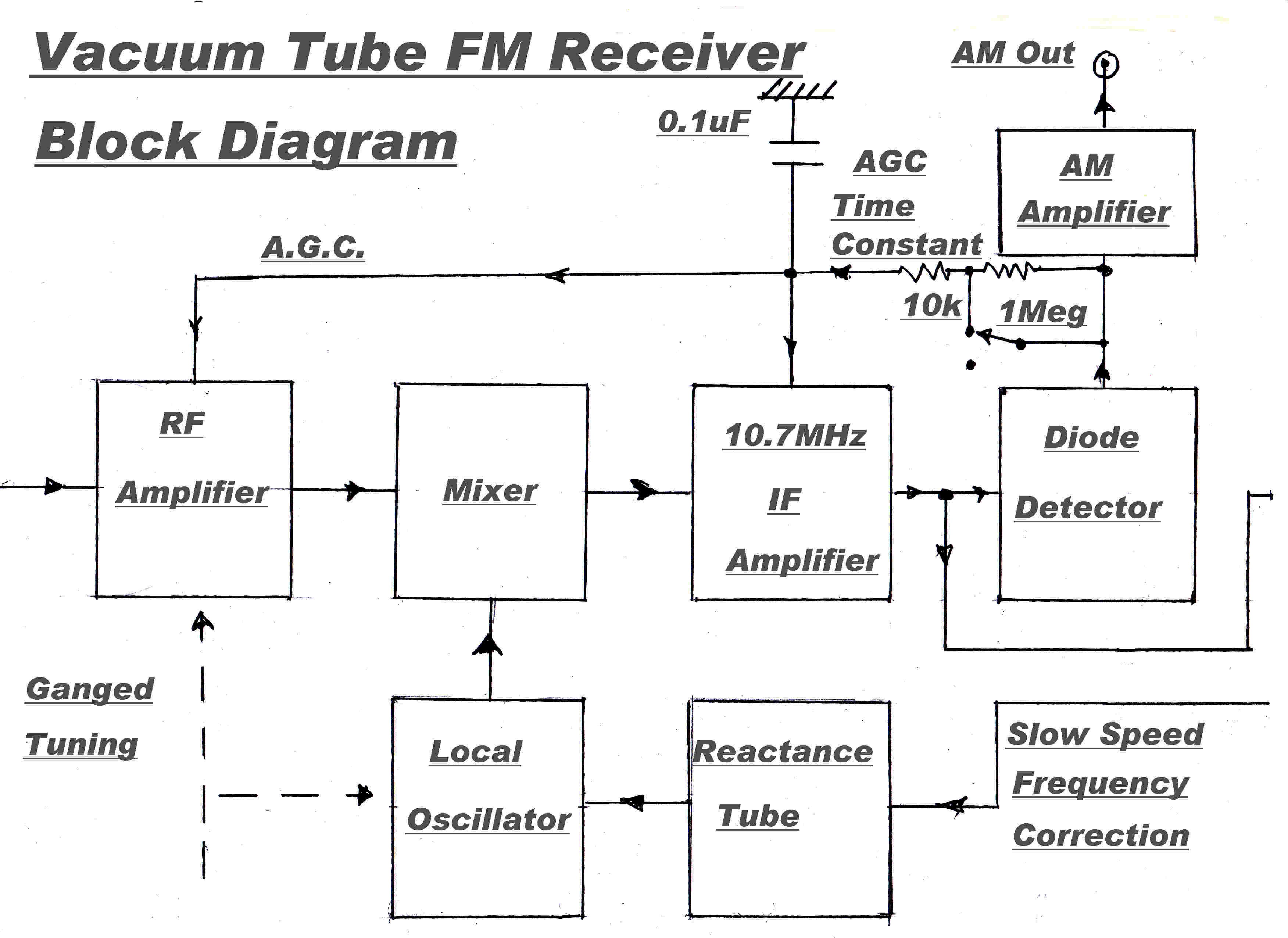
|
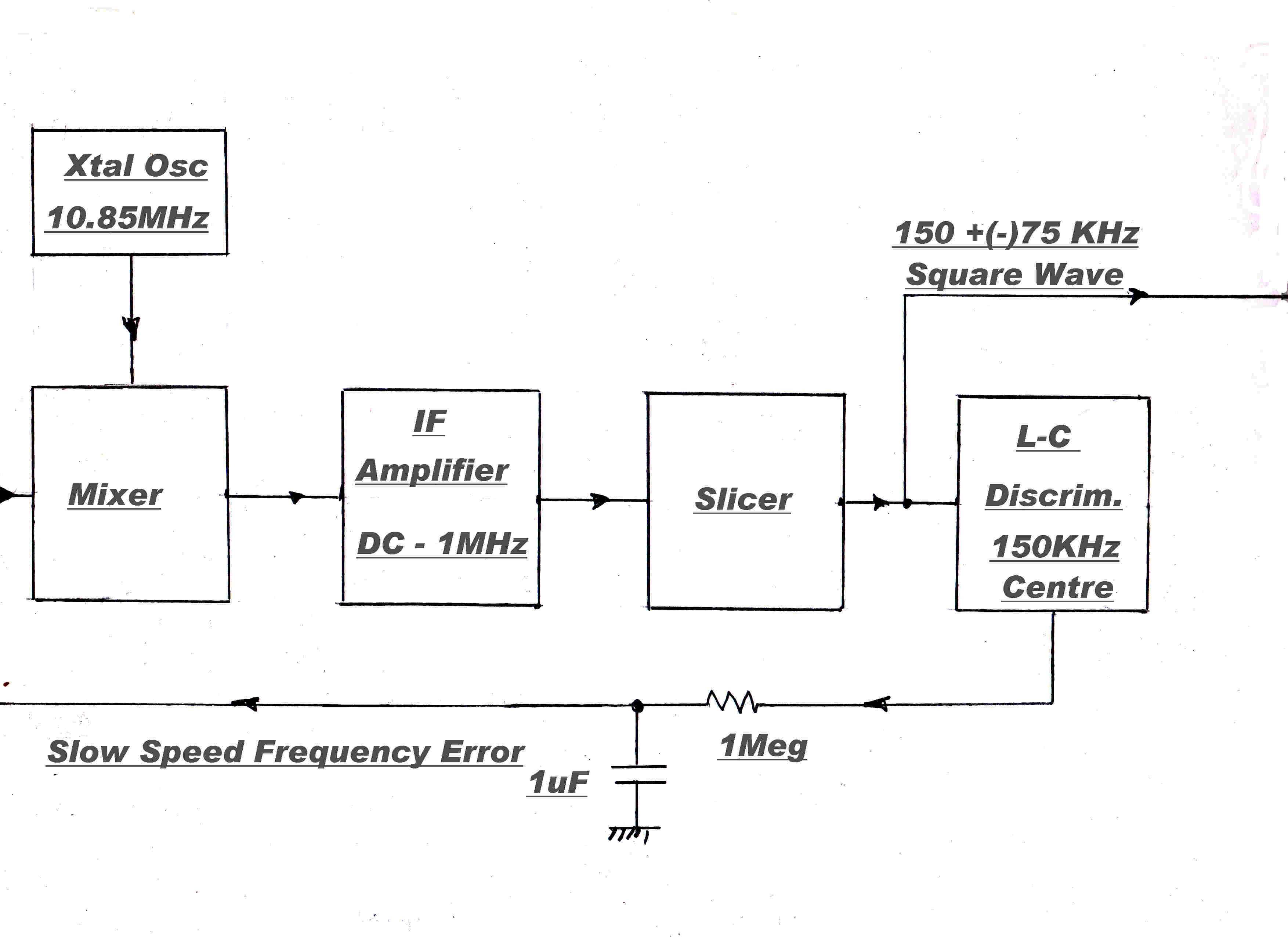
|
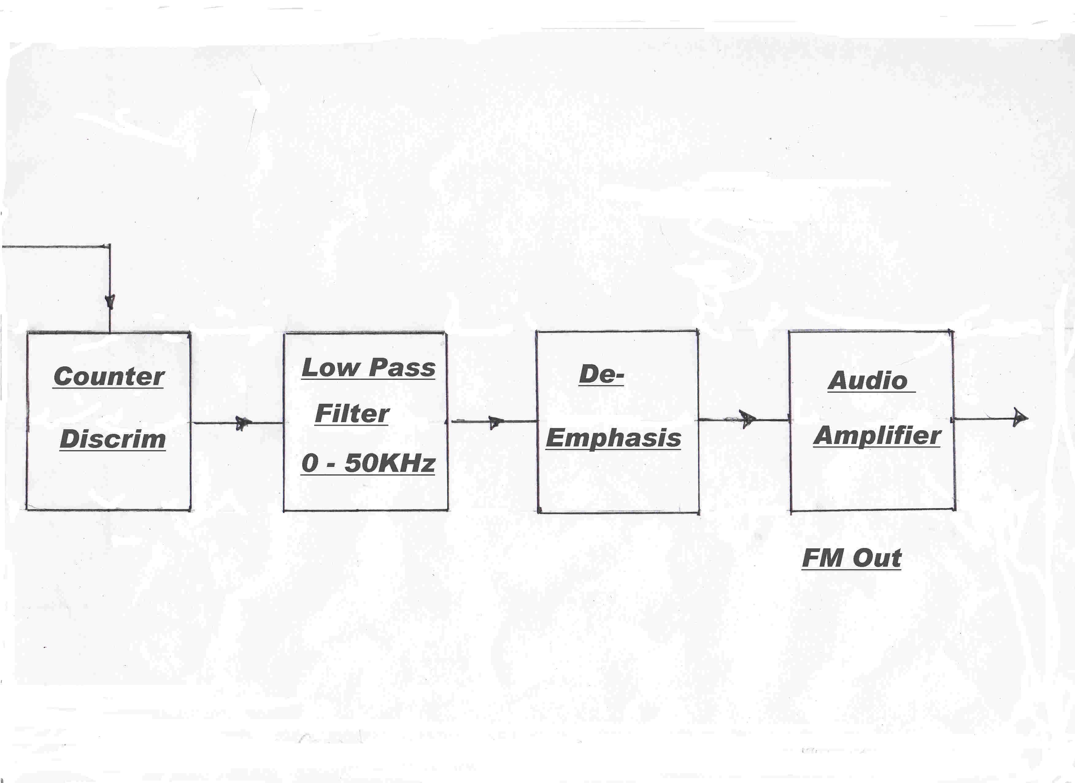
|
The AM modulation on an FM signal indicates the
distortion introduced into the FM content by multipath and
bandwidth limiting during transmission.
[ See the Discussion and Analysis in INTRODUCTION ]
Since it is important to get an estimate of the distortion occuring
to the FM along the transmission path, the first section of the tuner
was designed for AM with a readout of the incident AM.
The RF, converter and 10.7MHz IF stage were designed to
operate in a linear mode to minimise cross modulation of
incoming signals. No limiting or slicing was used in this section.
AGC was applied to the RF and IF stages, but not to the converter.
Converter AGC can change the impedance presented to the local oscillator
and so pull its frequency.
A slow time constant was introduced into the AGC loop for AM inspection.
Normal operation employed a fast AGC loop to get maximum suppression of
signal variation.
The design of the transfer function for the IF of an FM receiver
involves a very difficult compromise.
The ultimate high frequency distortion in the receiver is determined by the
amplitude and phase response of the IF amplifier.
Ideally, the IF amplifier should be as wide as possible with good phase linearity.
For good tuner selectivity, it should be as narrow as possible.
As the bandwidth is increased, so is the noise, so, eventually, there is a trade-off
between the small reduction in distorton and the increase in noise.
Since there was only one FM transmitter in Brisbane in the fifties ( on 91.1MHz )
the problem of selectivity was relaxed in the design.
The double conversion tuners used a first IF centered on 10.7MHz.
This had a fourth order Bessel response of +(-) 400KHz.
The second IF frequency was 200KHz.- the low frequency necessary for the counter
discriminator.
The second IF was essentially a low pass filter flat up to 1MHz.
Frequency drift of the local oscillator on 101.8 MHz caused an unacceptable drift
in the centre frequency of the 200 KHz IF, so a slow speed feedback loop to centre
the frequency was included.
The frequency error signal was generated by an L-C discriminator because of its
stability from zero error drift. A non-linear transfer characteristic is of
no consequence.
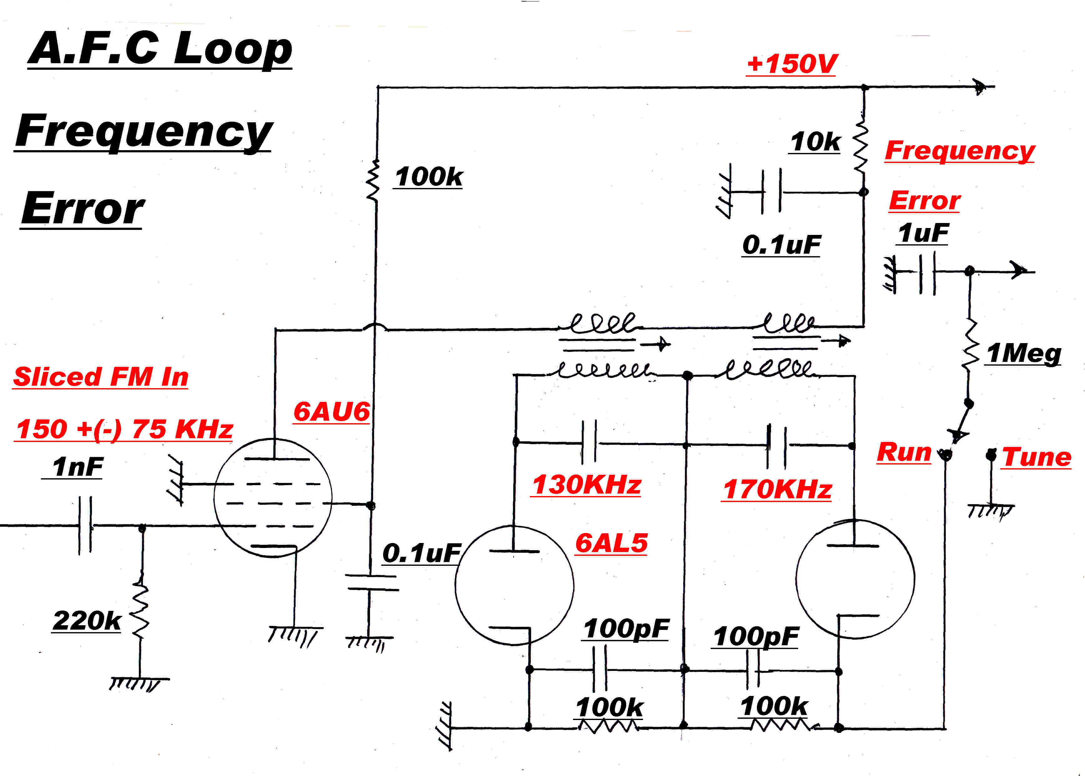 A typical L-C discriminator for frequency stabilisation
is shown opposite.
The two tuned circuits are detuned by the same amount on either side
of carrier to give zero output at carrier frequency.
The tuned circuits are temperature compensated if necessary.
As explained in the introduction, the usual explanation for
limiting in an FM receiver is WRONG!
It usually goes something like: Noise adds or subtracts to the amplitude
of an FM wave, so if we remove the AM we remove the noise.
Noise also alters the zero crossing points of an FM wave, and so phase
modulates it. This is equivalent to frequency modulation with the differential
of the of the noise.
The amplitude of the differential rises at 6db/octave, so we have
BLUE NOISE.
No amount of limiting will remove it!
AM is removed in limiters and slicers so that the detector will not respond
to it - it should respond ONLY to the FM component.
The optimum way to remove AM is by slicing - not limiting.
A slicer has the following logic:-
[1] If the FM wave is positive then the output is positive and constant
[2] If the FM wave is negative then the output is negative and constant
The action of the 6J6 slicers is easily seen in the circuit given below
In the sixties a special tube -the 6BN6- was developed for slicing.
These were never usd in the student tuners.
Since this site is devoted to vacuum tube technique, a brief description
will be given at the end of this section.
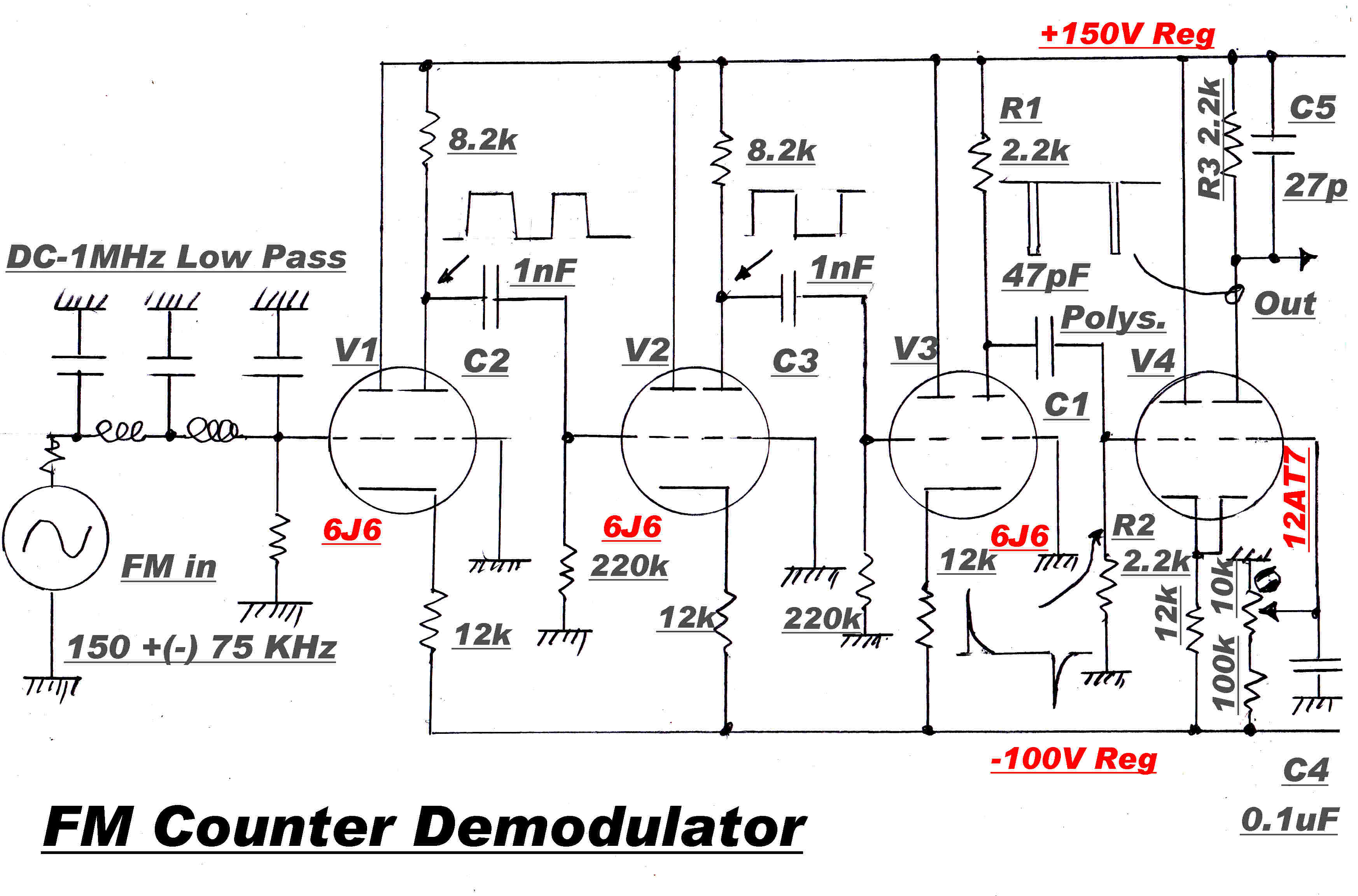 The steady state amplitude response of L-C networks
varies with frequency and this can be made the basis of an FM demodulator.
The steady state amplitude response from a tuned circuit detuned from the carrier
varies with frequency but in a non - linear manner.
More complicated networks in which the amplitude of the output varies with frequency
can be constructed, but, essentially, all are fudges or approximations to make
the output vary linearly with steady state frequency.
The Foster - Seely and Ratio discriminators are good examples of this approach.
There are two difficulties:-
[A] The analysis and synthesis is performed using steady state theory. This applies
to the FM signal only in the limit at very slow speeds or low frequencies.
It is not surprising that the predicted performance of these discriminators fails
at high modulation frequencies.
[B] The attempt at linearity is only a fudge or approximation. The transfer
characteristic is not inherently linear.
These discriminators, then, are not desirable in very high performance FM demodulators.
Counter demodulators are inherently linear and should be used.
The simplified circuit of a counter demodulator, including slicing
stages, is shown above.
Correctly designed, they are capable of demodulating FM signals with less than
0.1% distortion. They were introduced by RCA in 1936.
Their action relys on a very simple and basic law:-
If each cycle of FM produces a pulse of area A then in time T the
total area Atot is given by:-
Atot = f A T
If Atot is taken as the output, then it is linearly related to
the frequency f - the required law.
Note: It is imperative that A be the same for all cycles if the law is to hold.
This means that the pulse of area A produced by each cycle should be independent
of the last cycle - there must be no memory of that cycle.
It is found that the dielectrics of ceramic capacitors do have memory and are
not suitable in pulse forming circuits in FM demodulators.
Capacitors with a polystyrene dielectric are suitable.
In the above circuit the square wave output from the slicer V3 is differentiated
by the R-C network R1 C1 R2.
The tip of the negative pulse is clipped by V4 to produce an output pulse
of constant area.
The time constant τ of the differentiator is given by:-
τ = ( R1 + R2 ) C1
τ = ( 4.4 x 10³ ) 47 x 10-12
= 2.068 x 10⁻⁷ S
The transient response v(t) of the differentiator is given by:-
v(t) = K e-t/τ
The highest frequency fh presented to the modulator is
( 150 + 75 ) KHz = 225 KHz
So the shortest half period t is given by:-
t = 1/( 2 fh ) = 1/( 2 x 225000 ) = 2.222 x 10⁻⁶ S
The differentiated pulse at the end of the half cycle will have decayed by:-
e-t/τ = e- 2.222x 10⁻⁶ / 2.068 x -7
= 2.153 x 10⁻⁵
So there is little memory of the previous pulse and the demodulator is linear.
There are many ways of producing an invariant pulse for a counter demodulator.
[A] A monostable with a quick recovery time.
[B] Two delay lines with slightly diferent delays.
The sliced FM square wave is sent down both terminated delay lines.
A fast logic circuit produces a pulse when the delay lines have different
voltages on their terminations.
The pulse duration is equal to the difference in delays.
This was the system used in AMPEX video tape recorders. One tube -
the 6BN6 described below - can perform the necessary slicing and gating logic
all in the one envelope.
[C] The current pulse from the almost complete discharge of a capacitor from
a constant voltage source.
This was the system used in the first RCA counter demodulators in 1936.
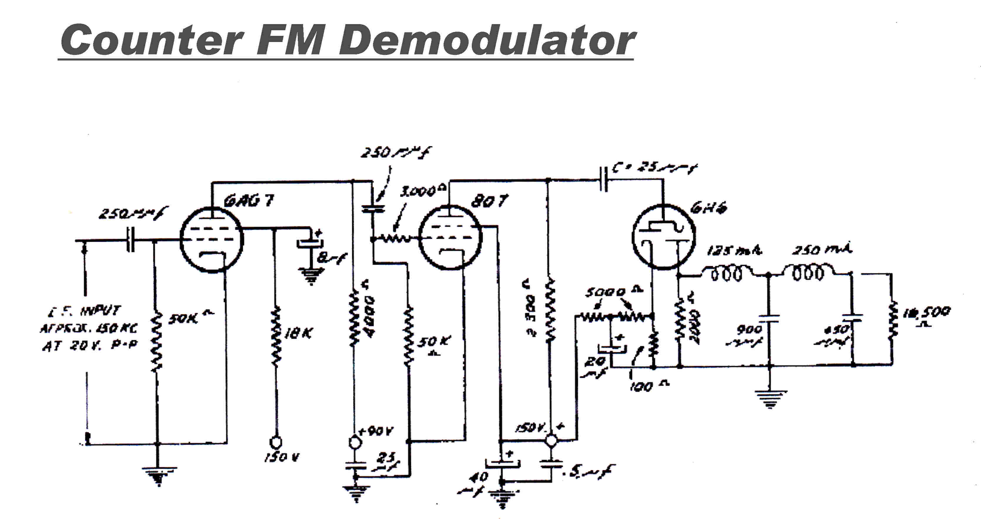
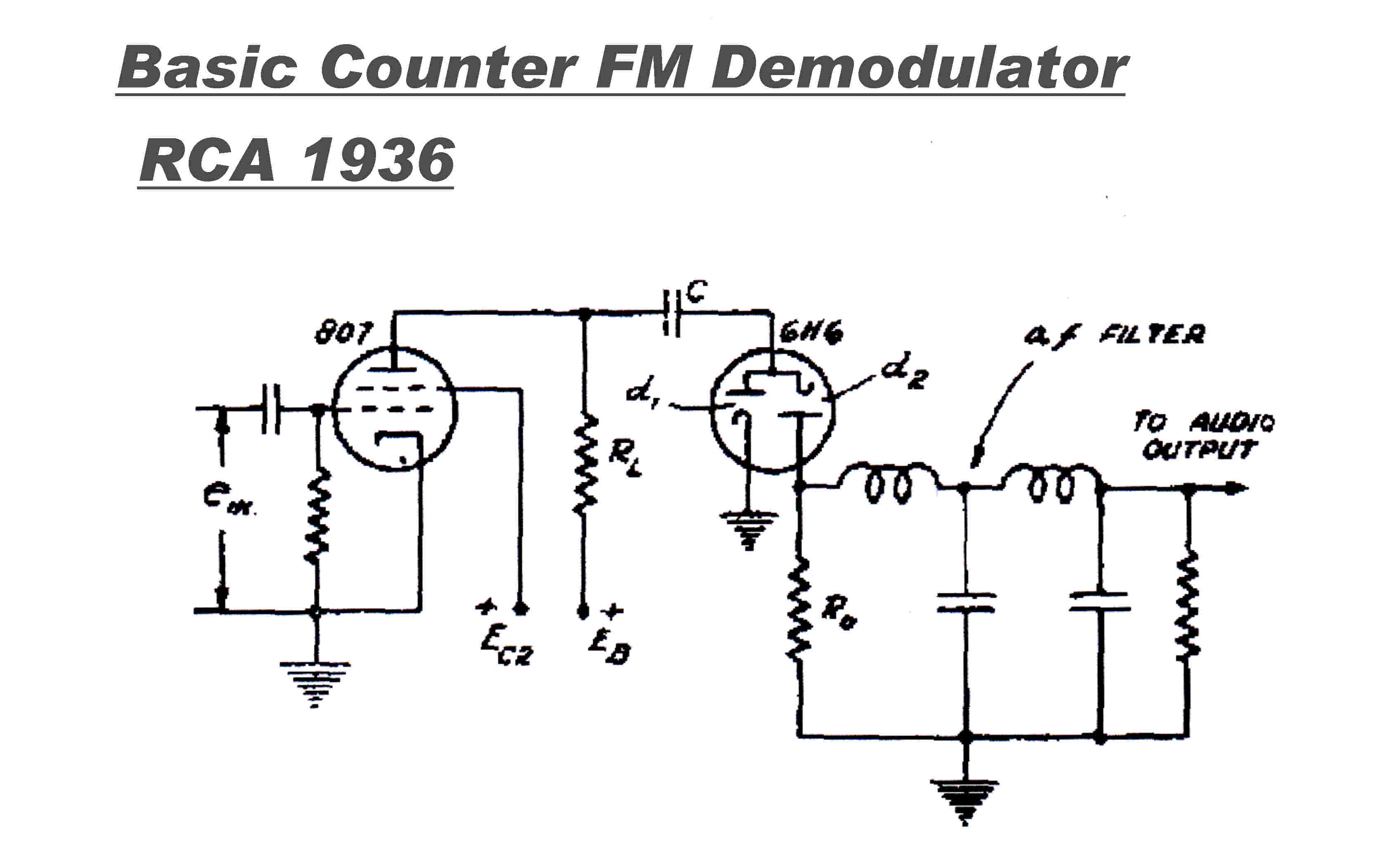 The basic topology of the 1936 RCA discriminator is shown :
then a working circuit with practical values.
The coupling capacitor C is fully charged via the left hand diode on the 6H6
on the positive half cycle, and then fully discharged into the output load
and filter on the negative half cycle.
The total charge on the negative half cycle does depend on the output voltage
stored on the output filter.This will introduce a small non-linear component
into the output. Reduction of the filter impedance will reduce the output and
the non-linearity to any tolerable value.
It is simple to overcome this small amount of non-linearity. See the above
circuit or the solid state discriminator in the frequency readout section of the
high quality AM tuner.
RCA counter discriminators are fully described in:-
GENERATION AND DETECTION OF FREQUENCY MODULATED WAVES
Stuart W Seeley : Charles N Kimball : Allen A Barco
RCA Review January 1942
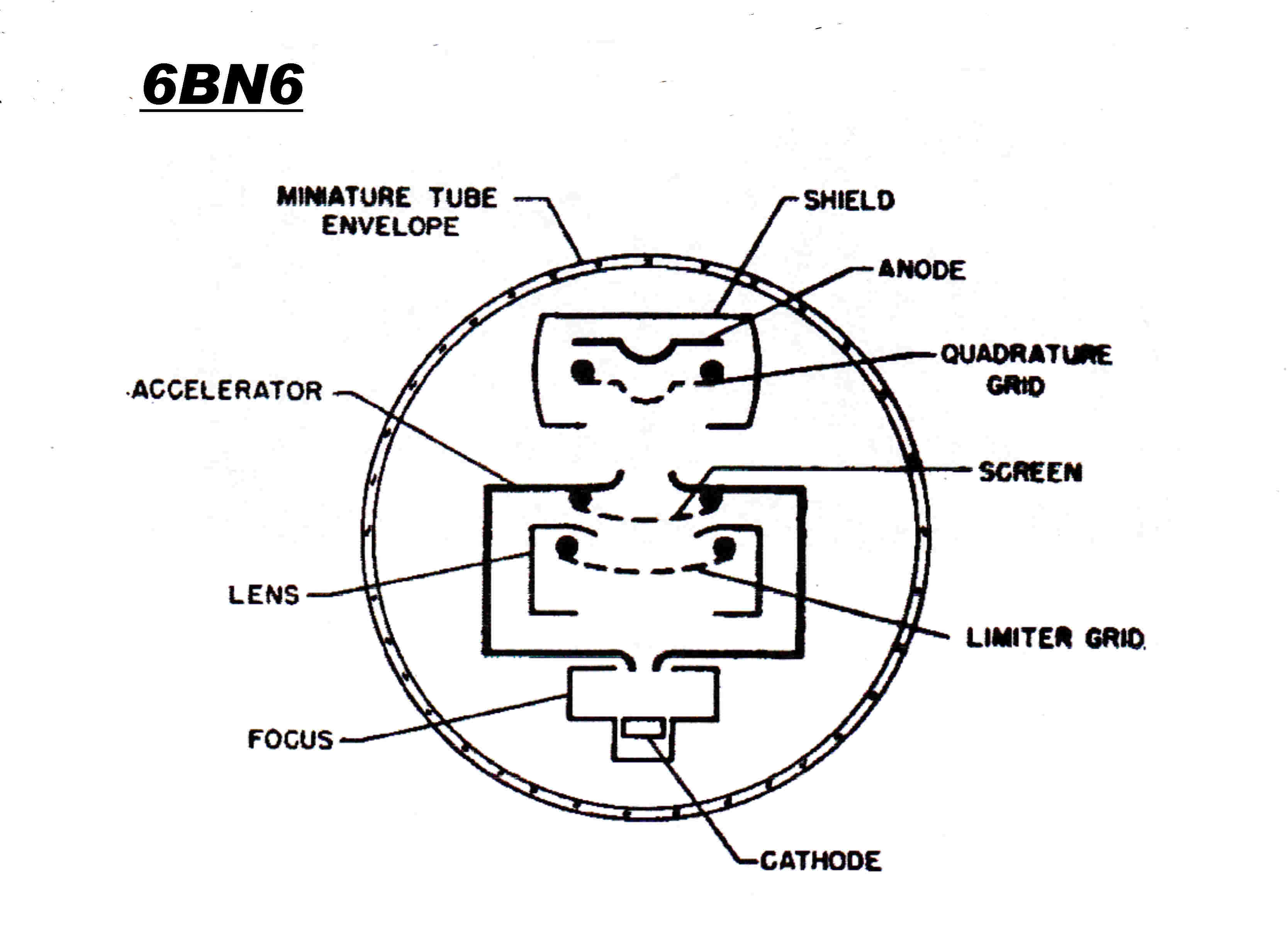
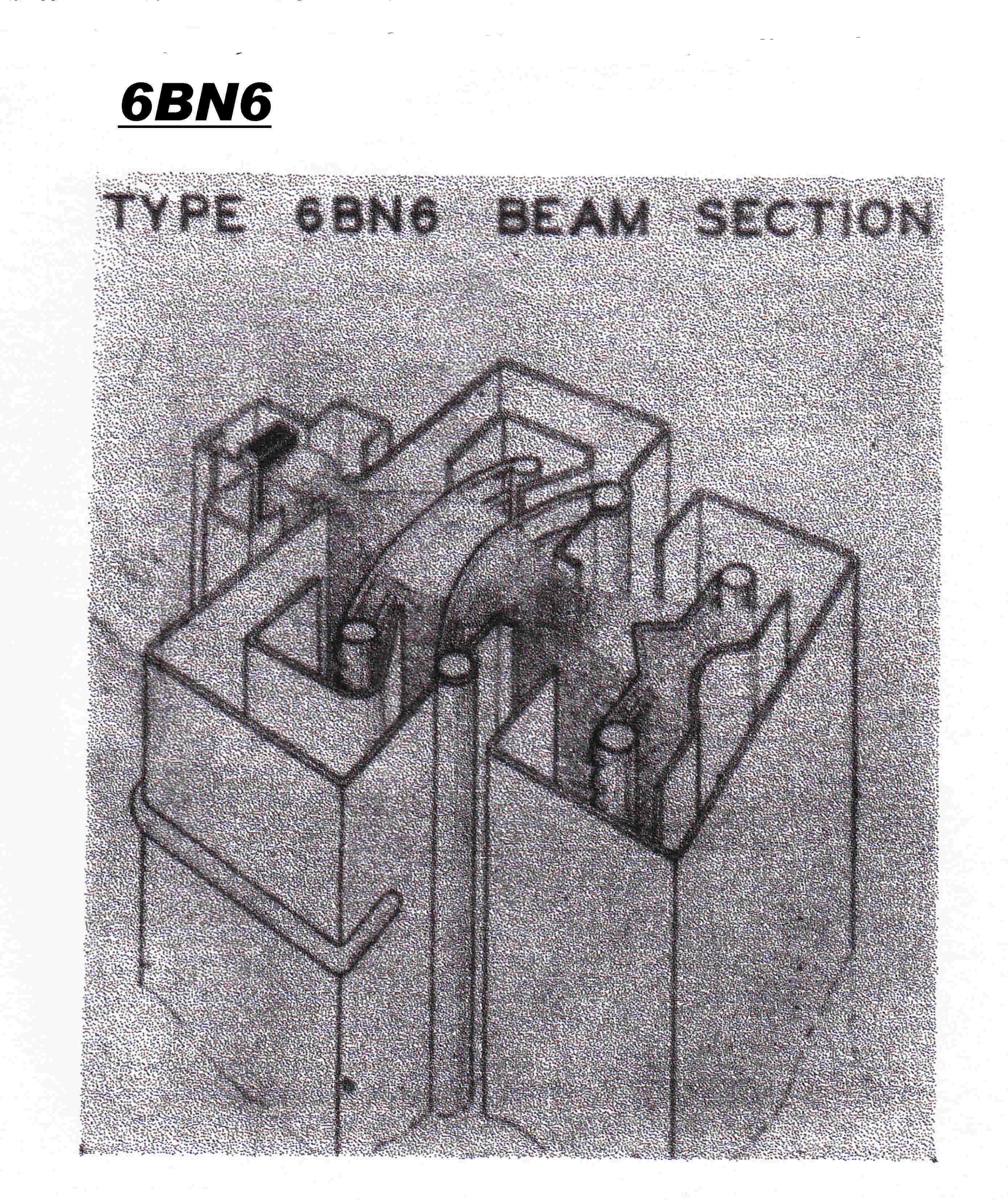 A special vacuum tube - the 6BN6 - was designed for
use in FM demodulators as a slicer and gate.
Two grids in series controlled the electron stream to form an AND gate.
The transfer characteristic of each grid rapidly changed from zero current to
a saturated current of a few milliamps to give a slicing action.
The tube employed an electron stream of uniform density aimed at a fine mesh grid.
The structure is shown opposite.
With the grid slightly positive, a few electrons would be intercepted by the grid
to give a small grid current. The rest would pass through to the plate.
If the grid is brought slightly negative some electrons are repelled
to form a space charge behind the grid. The space charge repells more electrons,
so the effect is cumulative and the electron strean is rapidly cutoff.
The electron stream is unstable and exhibits positive feedback.
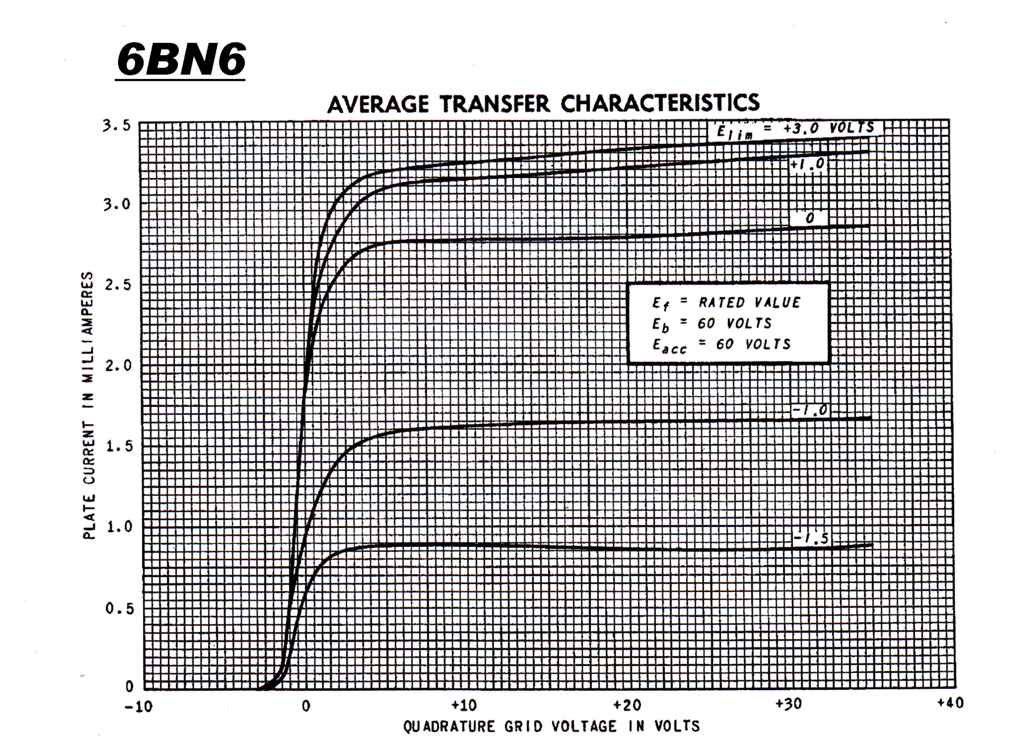
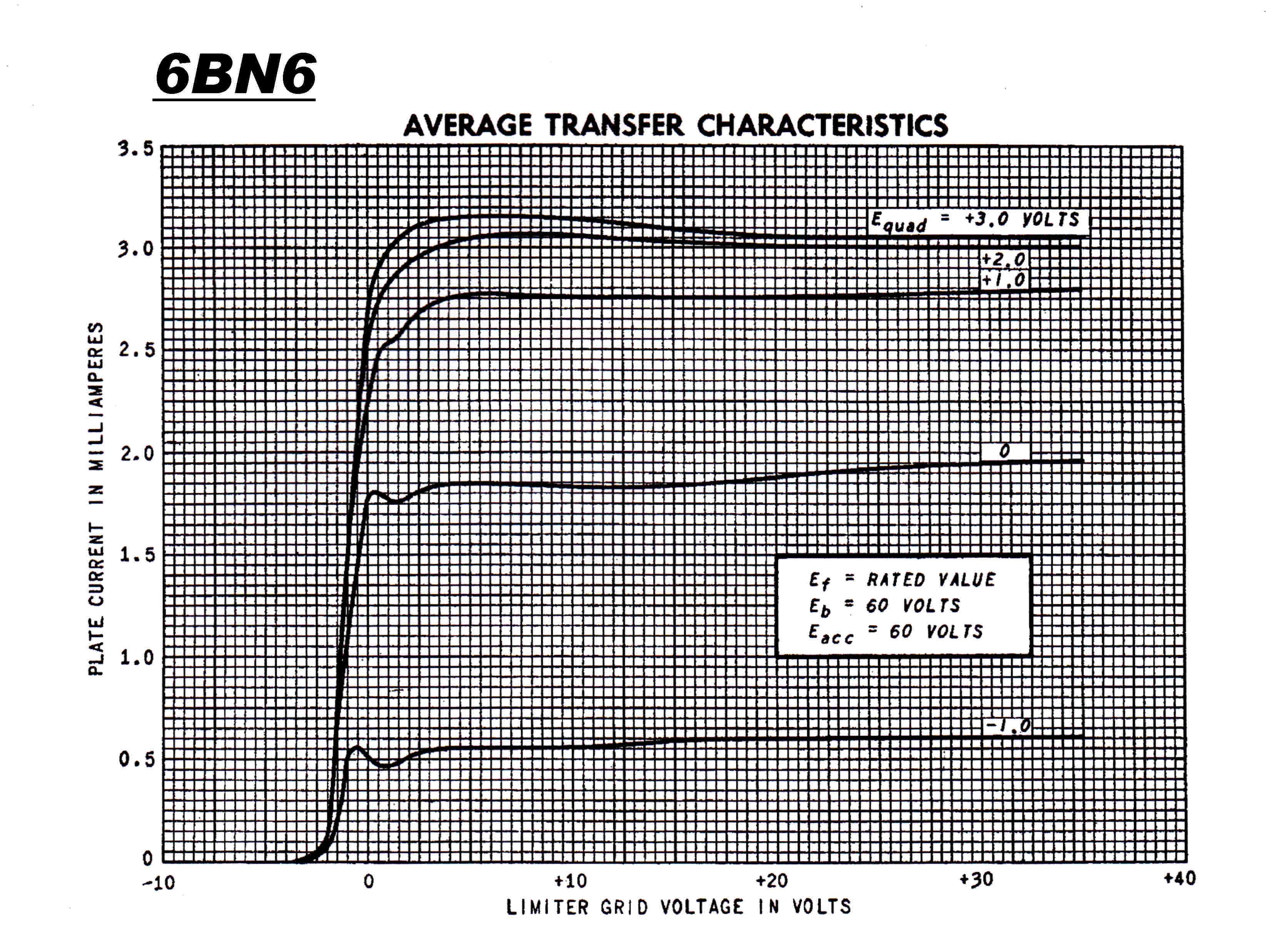 The transfer characteristic of each gate is shown opposite.
They exhibit almost perfect slicing action.
The maximum or saturated current is set by the electron gun and is not under
the control of either grid.
The discription of the tube came in two parts:
The 6BN6 Gated Beam Tube
Part1 : The Laboratory Protoytype and Its Circuit Application
by Robert Adler
Part 2 : The Commercial Realization of the 6BN6
by Allen P Haase
Zenith Radio Corporation
The final vacuum tube 4QR transmitter was installed in 1963.
The 50 KW transmitter was plate modulated at high level by a 30KW class B amplifier.
The transmitter is shown below.
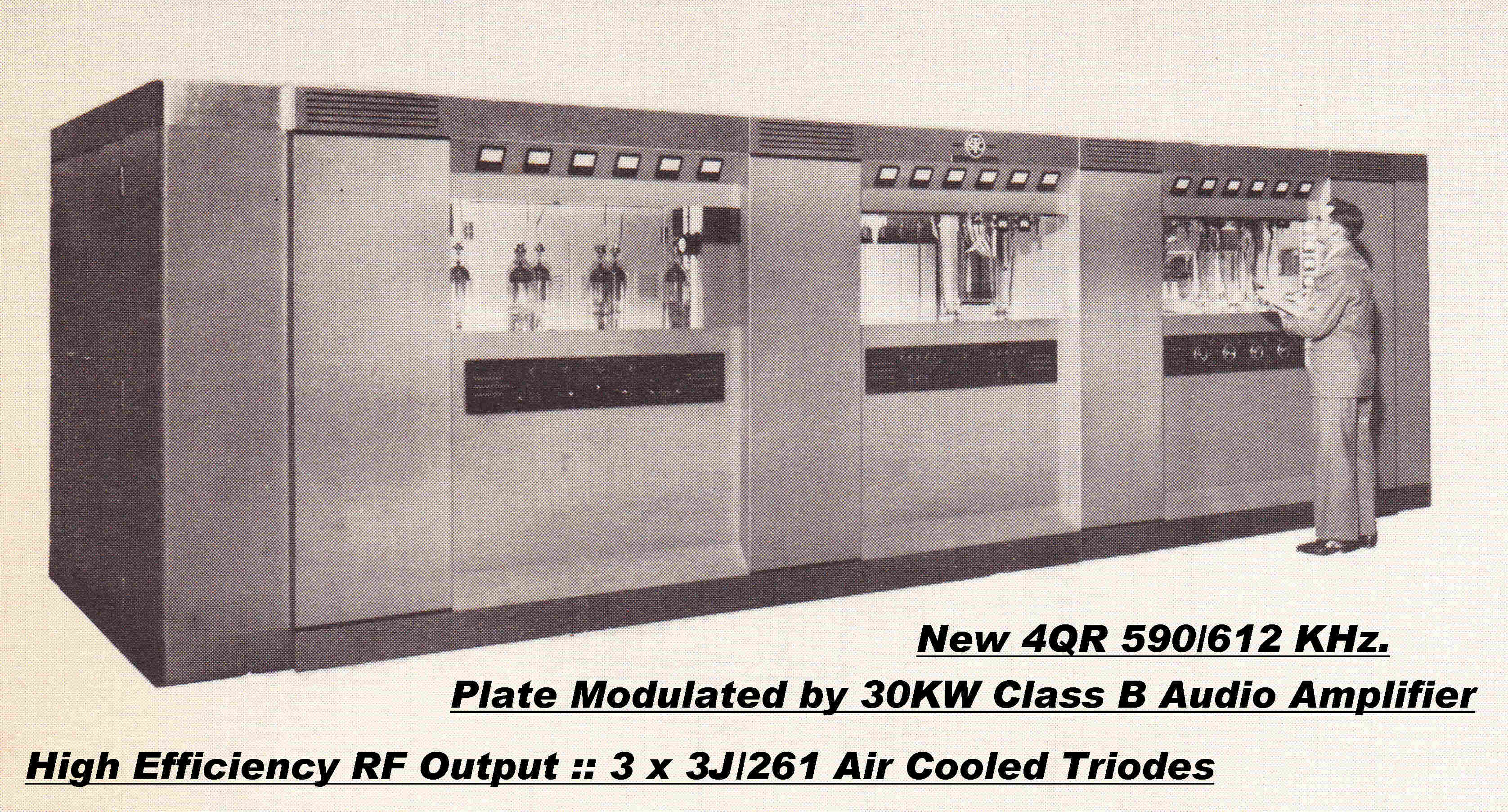
The transmitter is a good example of the final development of
the plate modulated transmitter with a class B audio amplifier as modulator.
It incorporated two notable circuit developments:-
[1] Direct coupled cathode follower drivers to the grids of the two audio output
tubes operated class B.
Heavy grid current at the top of the audio cycle presents a highly variable
load to the driver. This can produce horrendous distortion.
Early transmitters employed triode drivers coupled into the output grids with
a step - down transformer in an effort to produce a low output impedance.
The class B modulator in the 560KW WLW transmitter is a good example.
A better solution is a direct coupled cathode follower. This has a much
lower output impedance and improved frequency response.
A still better solution is to use output tubes which can support the
required plate current with no grid current, so the push - pull audio
output stage can be R-C coupled.
This results in much lower distortion and is a good illustration of the
interaction between vacuum tube and circuit design.
An example of a class AB1 modulator using 3X3000 tubes in an AWA
transmitter is given.
[2] An RF Output Stage with modified Grid and Anode Waveforms .
This results in much higher efficiency and much reduced distortion
in the plate modulation process.
HIGH EFFICIENCY
The higher efficiency - greater than 90% - is obtained by modifying the
grid and anode waveform with "lossless" tuned circuits in the plate
and cathode.
These are tuned to the third harmonic of the carrier.
The grid drive is an approximation to a rectangular pulse 120 degrees wide.
The plate voltage waveform is an approximation to a square wave.
DISTORTION REDUCTION -- PLATE MODULATION
The waveform modifications to increase efficiency have the serendipitous
effect of linearising the plate modulation transfer characteristic.
Almost something for nothing - a rare event in the physical universe!
Ideas for increasing the efficiency of vacuum tubes as generators of RF power
go back to at least 1917.
The ideas were assembled and turned into a practicable system useful in an
AM transmitter b; V J Tyler of the Marconi Company. See:-
A NEW HIGH-EFFICIENCY HIGH-POWER AMPLIFIER
The Marconi Review
Jan 1958 -- Dec 1958
Vol XXI Nos. 128 - 131
Note: Some of the diagrams in the explanation below are based on diagrams
from this paper.
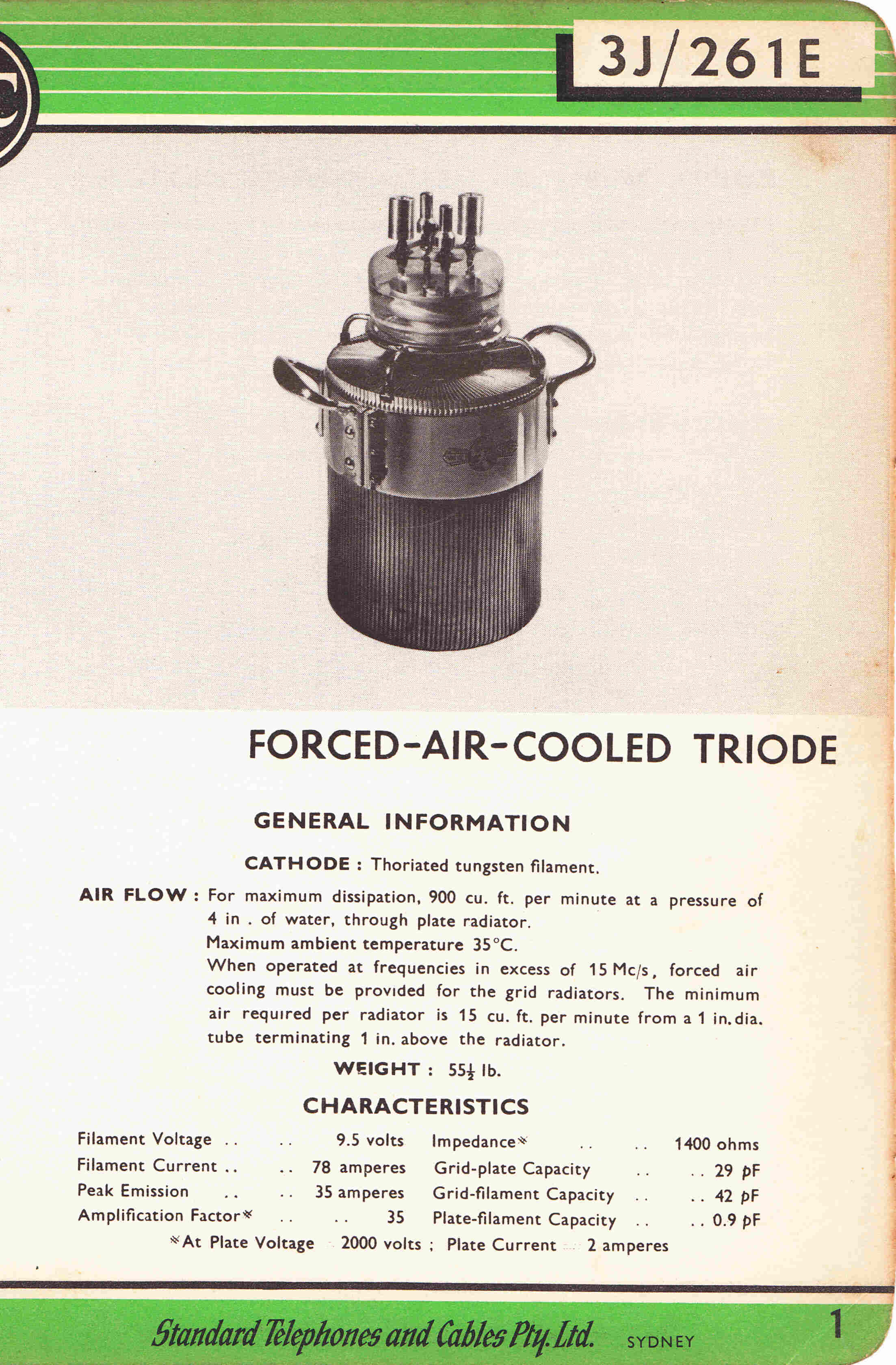
|
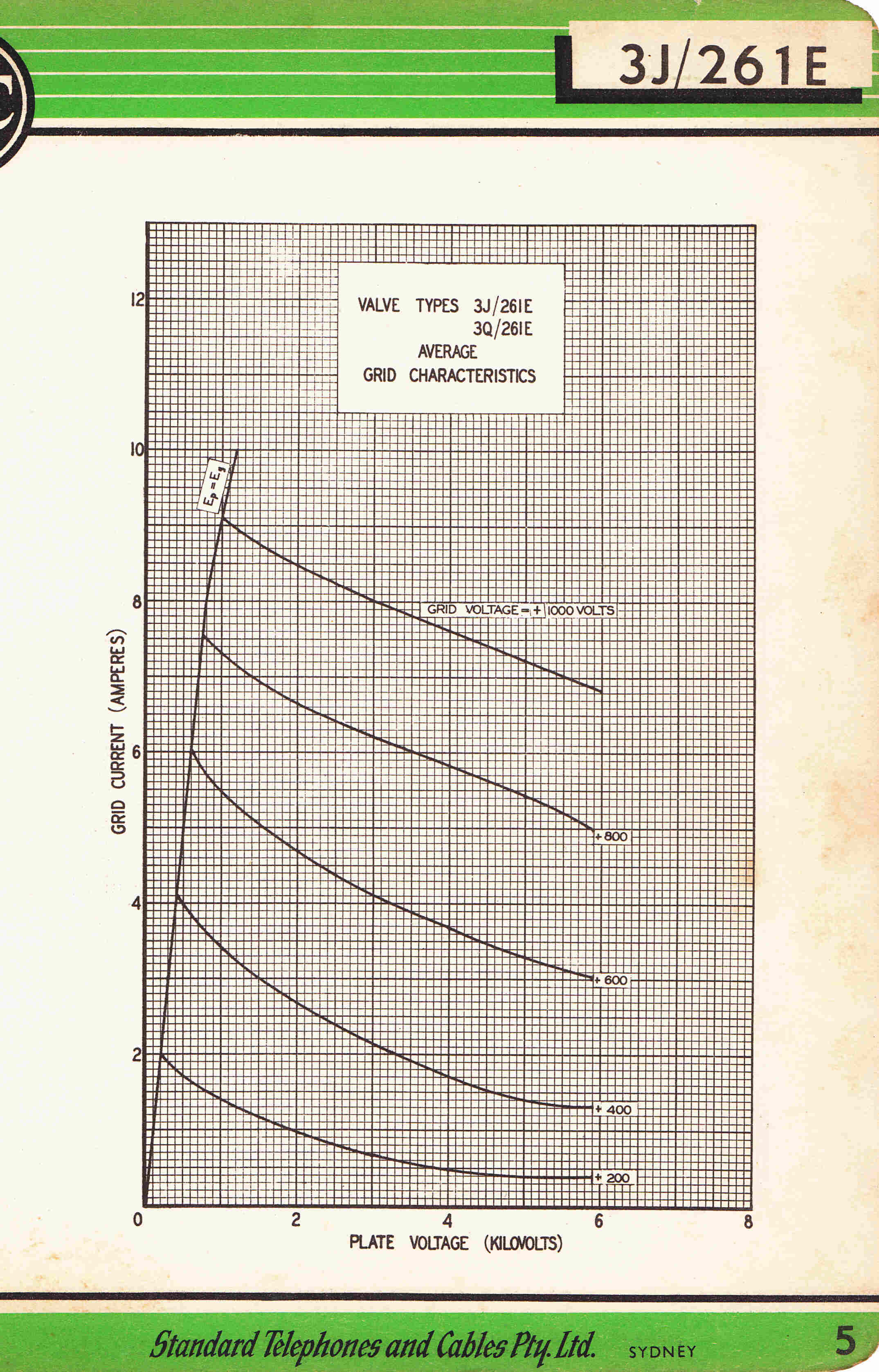
|
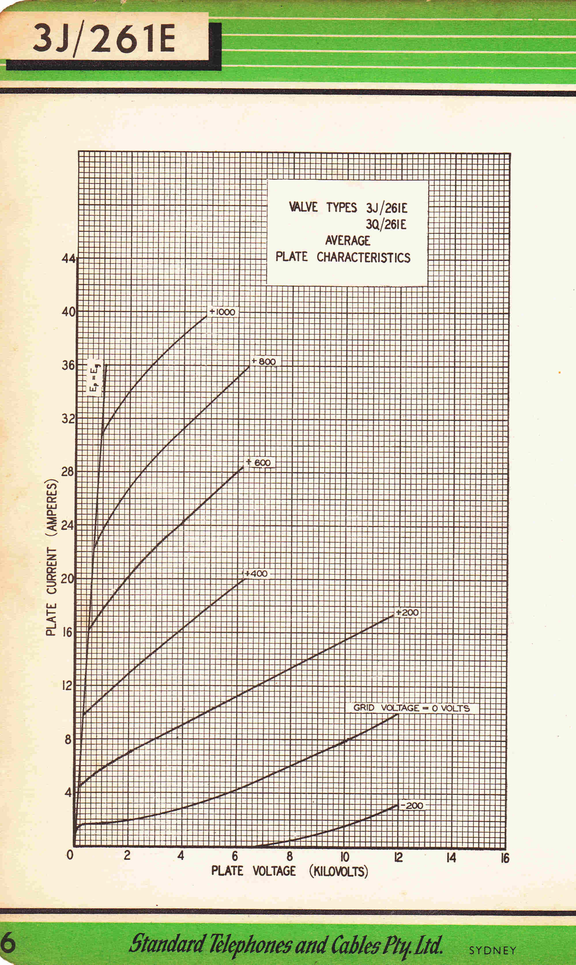
|
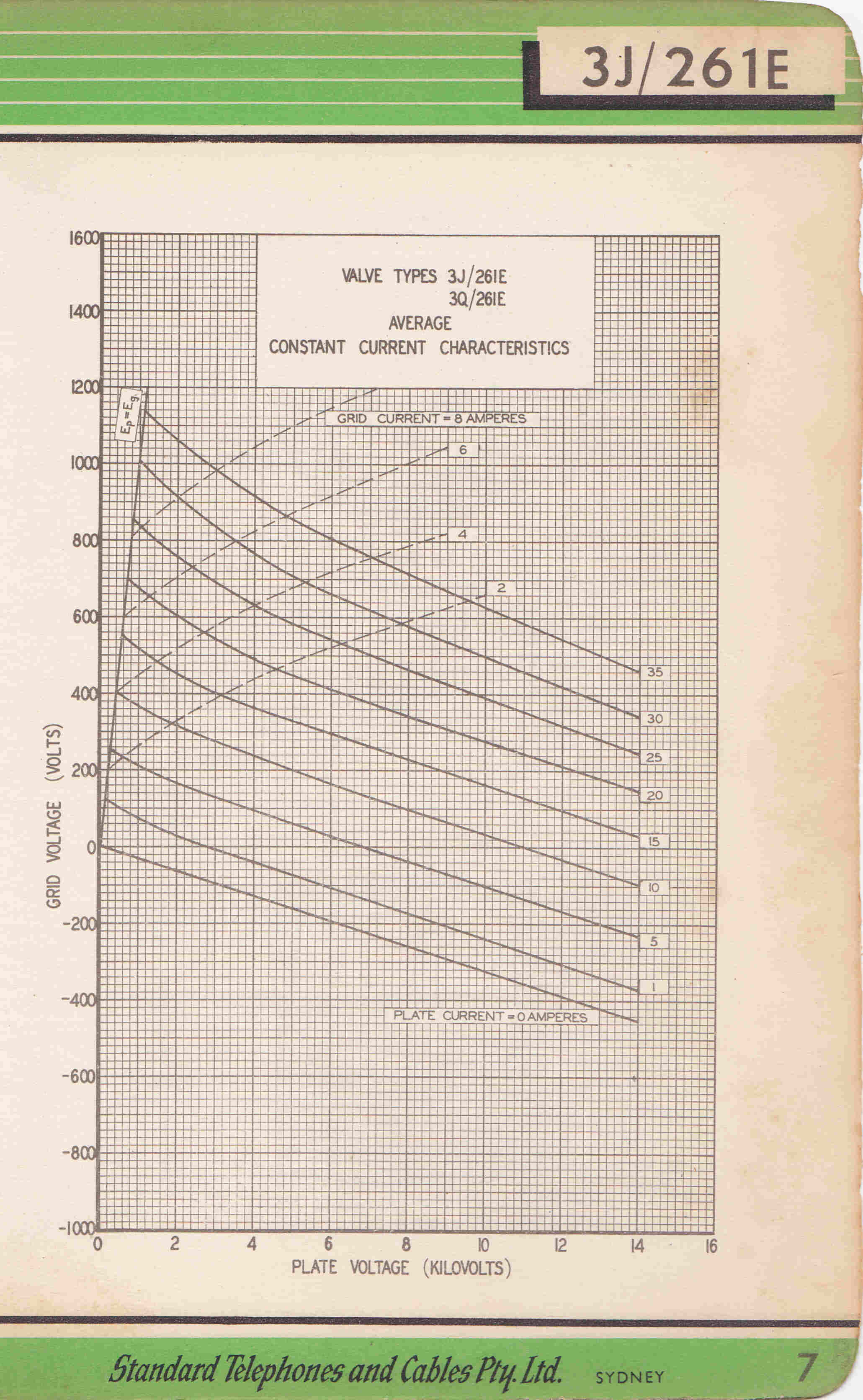
|
|
Modulator class B Output Stage |
RF Output: |
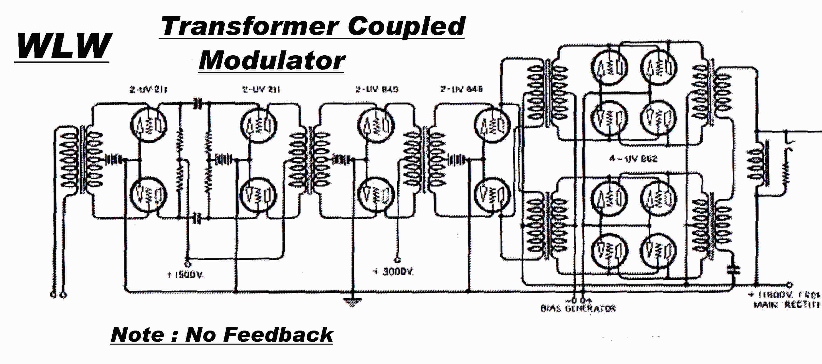 The transformer coupled modulator used in the 500KW
plate modulated WLW transmitter represents early practice.
See:- The WLW 500KW Broadcast Transmitter
Proc IRE Vol. 22 No. 10 Oct 1934
The plate resistance of the low mu triodes driving the output
grids was transformed down in the coupling transformer in an attempt
to provide a low driving impedance for the "peaky" grid current.
The output resistance coupled with the leakage reactance of the transformer
still produced considerable distortion.
Note that there is no feedback on the amplifier.
Feedback theory was still being developed at Bell in the early thirties.
The number of coupling transformers produced a forward transfer function
which precluded the use of overall feedback regardless of the state of
the theory.
In later designs, such as the 50KW 4QR transmitter, a direct coupled
cathode follower provided the low output impedance to drive the
grids of the final stage.
This greatly improved the response and lowered the distortion.
A typical direct coupled cathode follower class B modulator output
stage is shown below.
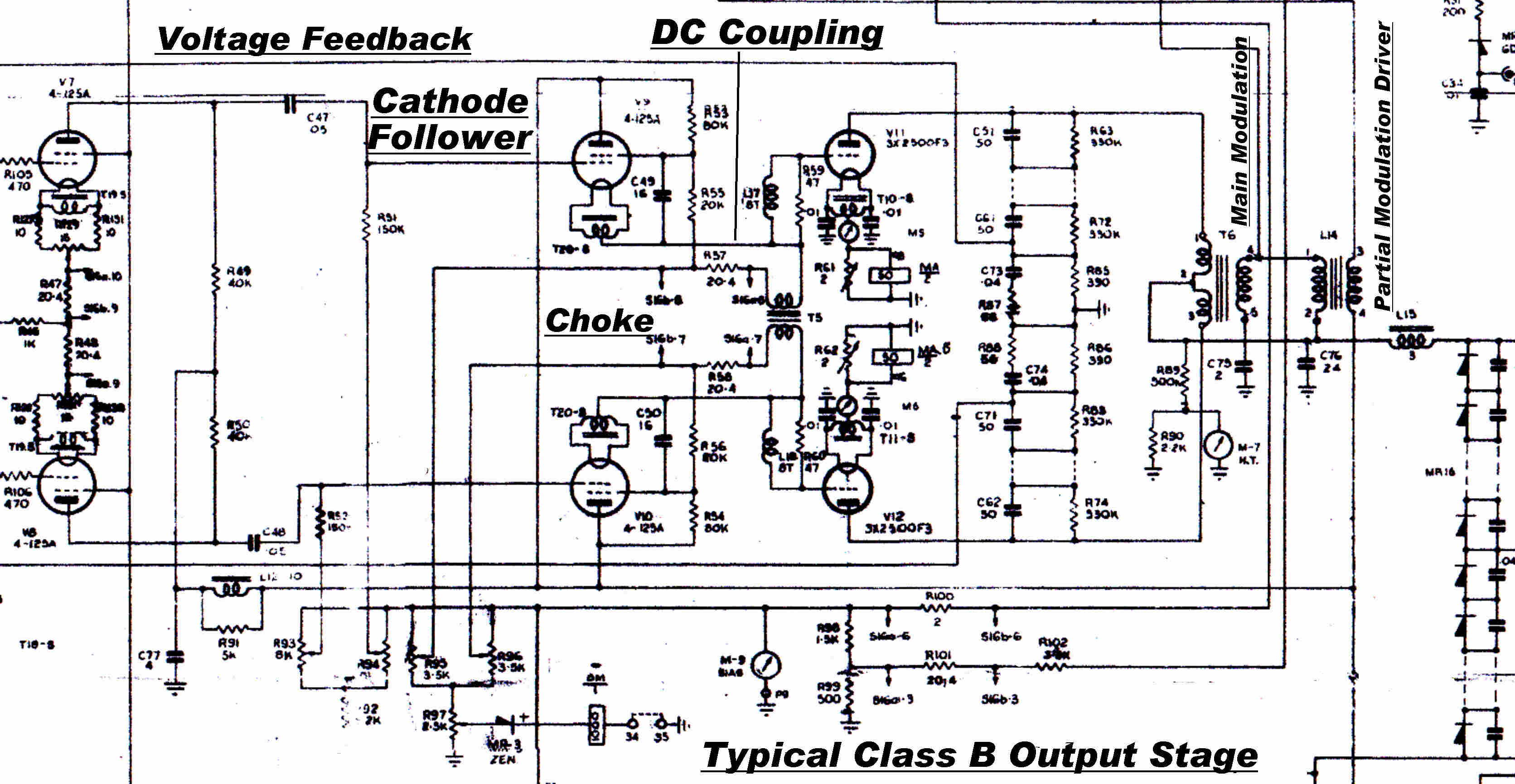 The cathode follower tube acts as a pentode since its screen is bypassed to
its cathode via C49.
The cathode (filament) is coupled directly to the grid of the output tube
via the parasitic suppressor L17 - R59.
This has a very low impedance at audio frequencies.
Towards the end of the vacuum tube era, tubes were developed
in which the grids remained negative with no grid current while supporting
large plate currents.
The problem with grid currents vaniished and circuit design was simplified
- a good example of the interplay between vacuum tube and circuit design.
The circuit of an R - C coupled class AB1 modulator
in an AWA high efficiency plate modulated transmitter is shown below .
Excellent design practice in the feedback loops is also evident with the provision
of both low and high frequency stabilising networks.
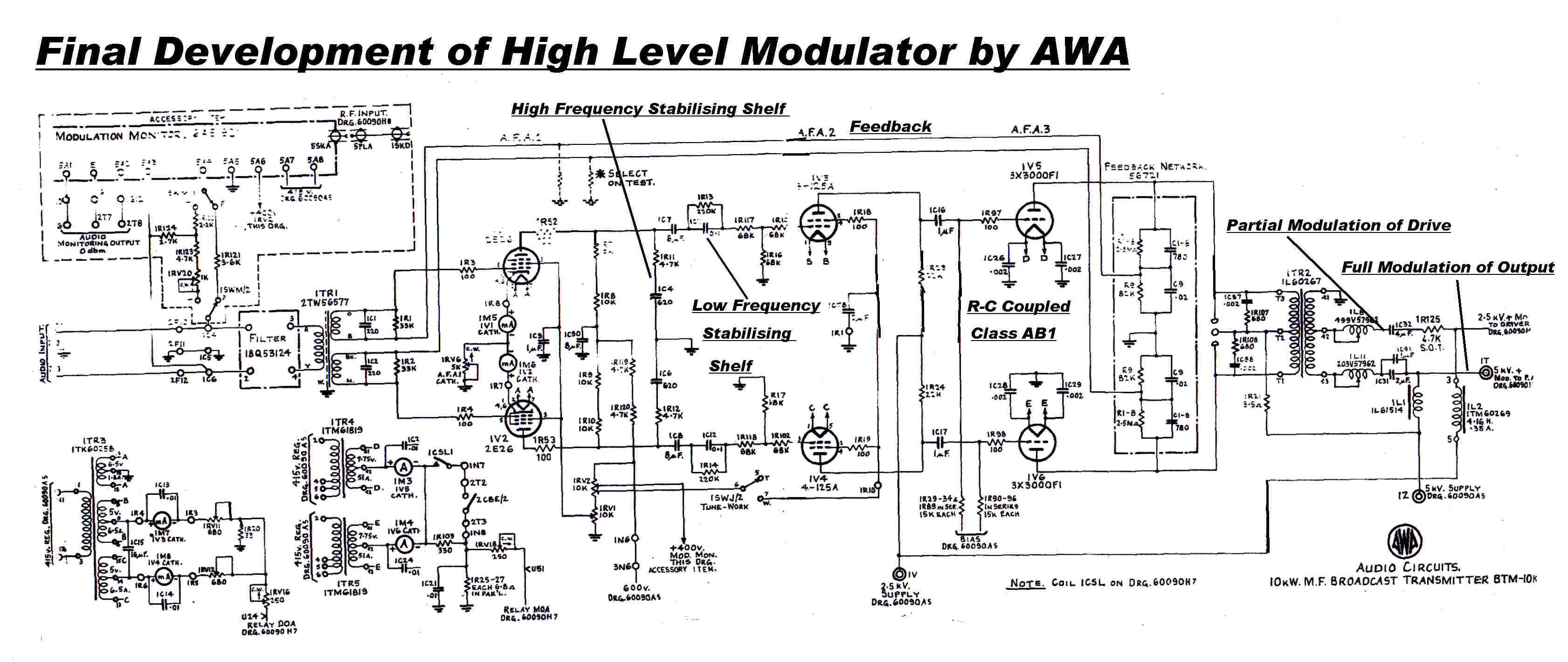
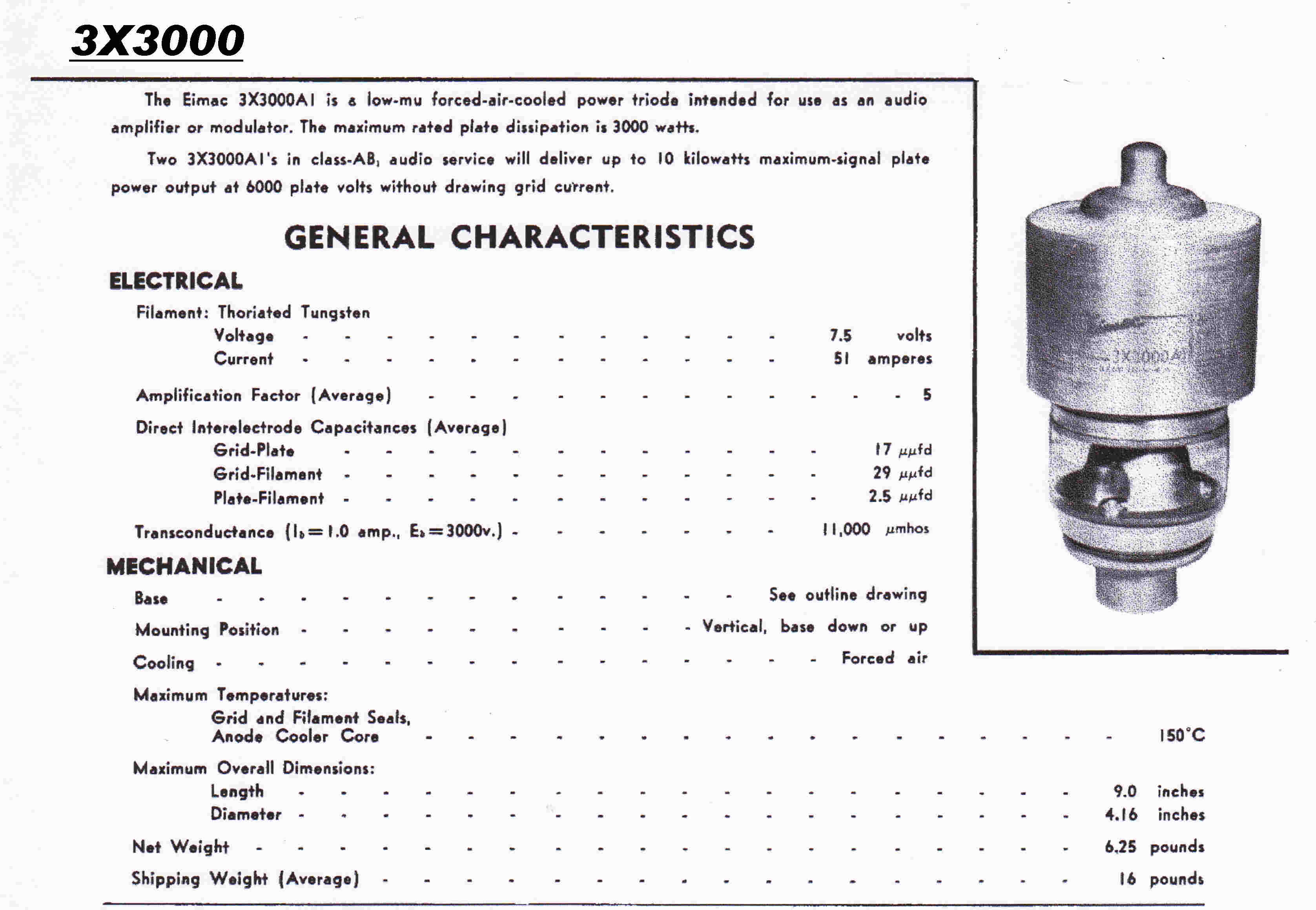
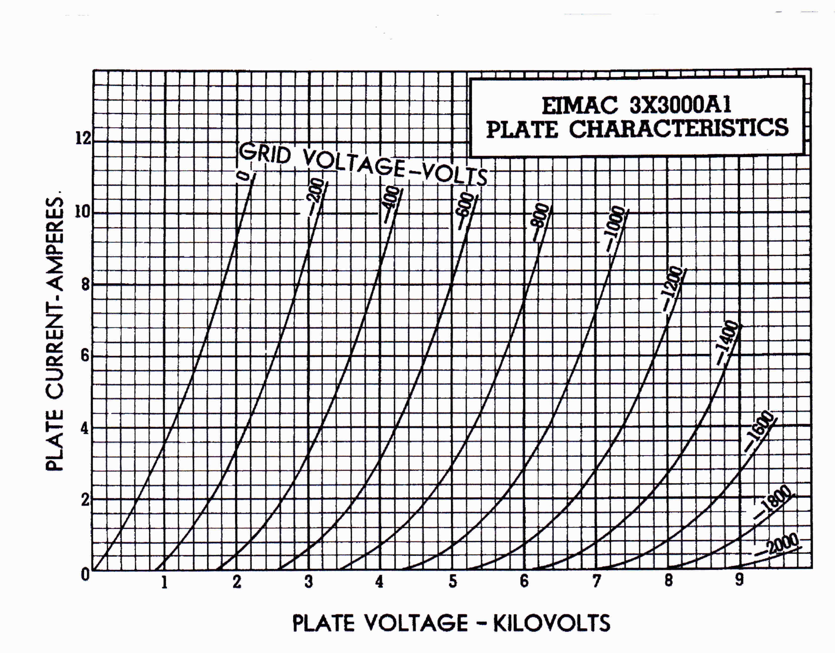 The Eimac Tube Design that made the class AB1 modulator possible.
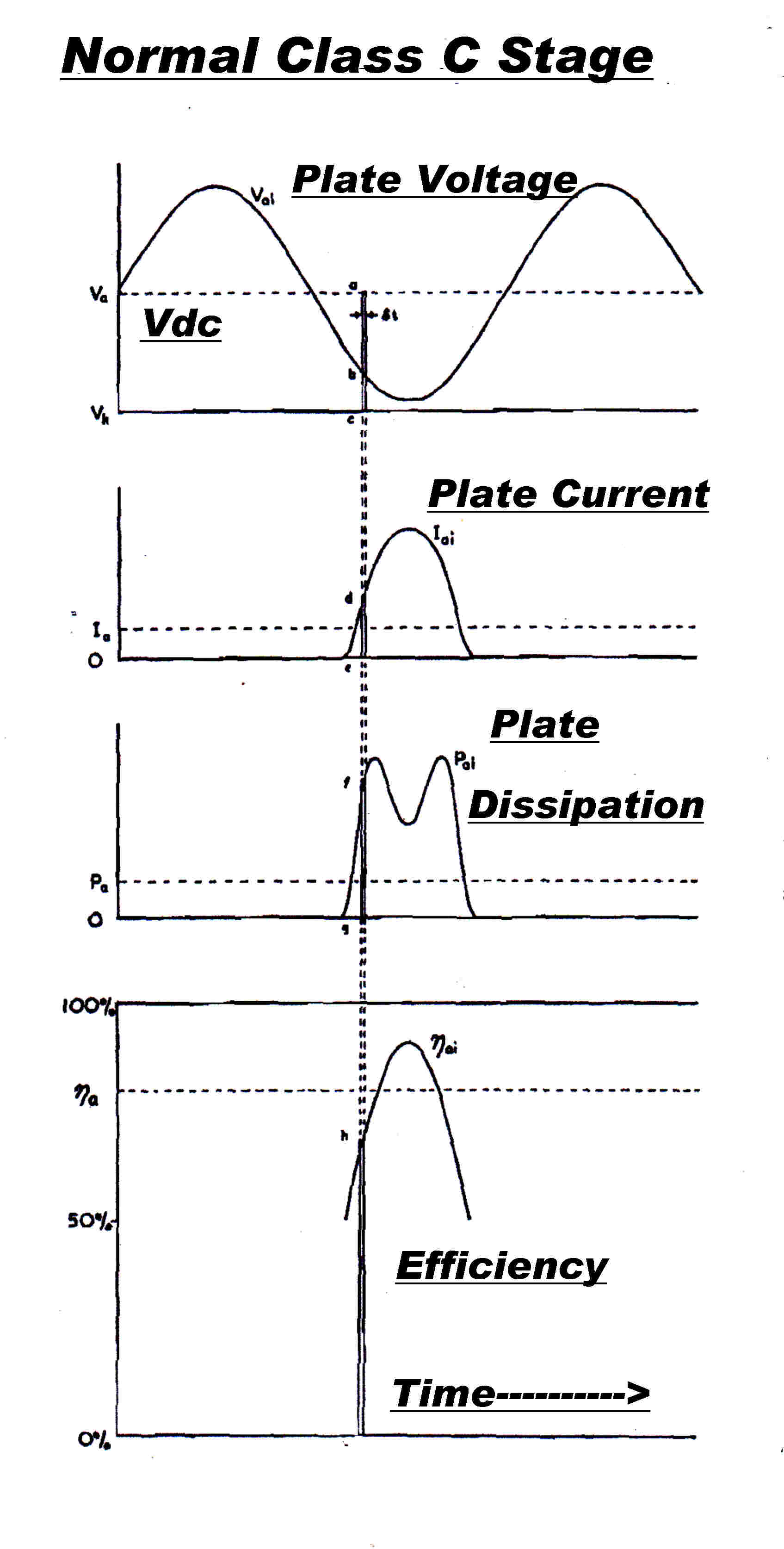
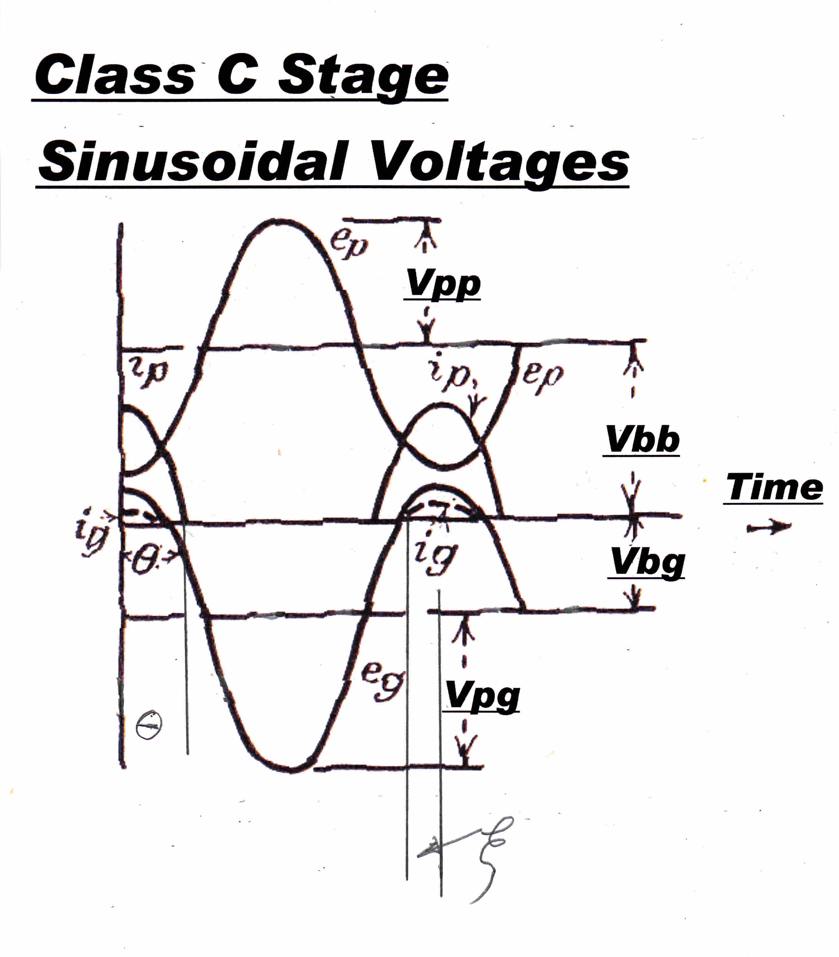 The waveforms in a classic class C stage are shown on the right.
Both the plate voltage swing and grid drive are sinusoidal.
The plate current pulse approximates a truncated sine wave with a half angle
of conduction θ.
The grid current pulse approximates a sin2 pulse with a half
angle ζ.
For class C :: 0 < ξ < θ < 90 degrees.
Although the plate current is small at the start of the pulse it occurs at
a high plate potential and causes significant plate dissipation.
A plot of the instantaneous plate dissipation and efficiency is given.
Maximum plate dissipation does not occur at maximum plate current, but on
the side of the current pulse.
It is apparent that the plate dissipation will fall and the efficiency
will rise with a very narrow plate current pulse, say 5 degrees.
What are the implications?
[1] The input power must remain (approximately ) the same to give the
same output power.
Now the input power equals Vdc x Idc, so the DC input current must
remain about the same.
Since the conduction angle θ is now very small, the plate current
peak must be greatly increased to give the same DC.
[2] The very high peak plate current cannot be supported by a vacuum tube
and, so rules out lowering the conducion angle as a method of
improving efficiency.
The very high plate current cannot be supported for two reasons:-
[3] Space charge between grid and plate prevents high plate currents at
low plate voltages.
[4] For long life, the pure tungsten filaments of vacuum tubes are
run at a temperature to produce just a little more emission than
the peak plate current demand.
The demand for extremely high peak currents would then give rise
to impossible filament designs.
High efficiency with high power output can be obtained by modifying
the shape of the plate voltage and plate current waveform.
This is described below.
Class C stages, and especially plate modulated class C stages,
are highly non-linear.
Until the advent of fast digital computers graphic design prevailed.
If linearising assumptions are made, useful closed algebraic solutions
can be found.
While only approximate, they provide useful insight into class C behaviour.
They are also useful in establishing the parameters before the start of
a more detailed non- linear design.
PLATE CURRENT PULSE
If we approximate the plate current pulse by a truncatred sine wave : then :-
ip(φ) = I[ cos(φ) - cos(θ) ] for -θ < φ < θ
ip(φ) = 0 elsewhere
GRID CURRENT PULSE
In most class C stages the grid is driven to approximately the same positive
potential as the plate. This results in the build up of space charge between
the grid and the plate. This reflects electrons back towards the grid to
give a "peaky" grid current response.
This can be roughly represented by :-
ig(φ) = I[ cos(φ) - cos(ξ) ]2
for -ξ < φ < ξ
ip(φ) = 0 elsewhere
FOURIER ANALYSIS
Now subject the above equations to Fourier Analysis
ANODE CURRENT
We are interested in the ratio of the peak anode current to the DC anode current
Ippk / Ipdc and the ratio of peak fundamental
plate current to the DC current Ippkf / Ipdc
Ippk / Ipdc =
π [ 1 - cos( θ ) ] / [ sin( θ ) - θ cos( θ ) ]
Ippkf / Ipdc =
[ θ - ( sin( 2 θ ) ) /2 ] / [ sin( θ ) - θ cos( θ ) ]
GRID CURRENT
We are interested in the ratio of the DC grid current to the peak grid current
Igdc / Igpk and the ratio of peak fundamental
grid current to the peak grid current Igpkf /
Igpk
Igdc / Igpk =
[ ξ ( 1/2 + cos2( ξ ) ) - ( 3/4) sin( 2 ξ ) ] /
[ π ( 1 - cos( ξ ) )2 ]
Igpkf / Igpk =
[ (1/12)sin(3 ξ ) + (3/4)sin( ξ ) - (1/2)sin( 2 ξ )cos ( ξ)
- ξ cos( ξ ) + sin( ξ )cos2( ξ ) ] /
[ π ( 1 - cos( ξ ) )2 ]
where:-
θ = (half) plate current conduction angle
ξ = (half) grid current conduction angle
CLASS C DESIGN TABLE
Although extremely useful, the above equations are a pain to evaluate by hand,
and so their evaluation formed my first digital program.
The computer fully occupied the basement of a large building : the clock
frequency was 455KHz and 4K of RAM was generously provided.
Data entry was on punched cards. After several days the results were returned
on punched paper tape and then printed out on a teleprinter.
The results are still very useful and shown below.

THE IDEAL CLASS C STAGE -- PERFORMANCE LIMITS
By asuming an ideal tube with no voltage drop, and using the values from the
table, it is possible to get a better "feel" for the parameters governing
the behaviour of a clas C stage.
Some fundamental equations of the ideal stage:-
Pin = Vdc Idc
vp(t) = Vdc - Vppkcos( ωt )
: plate voltage swing sinusoidal
Let the peak fundamental plate current be:- Ippkf
Then the power out Pout at fundamental frequecy is given by :-
Pout = 1/2 Vppk Ippkf
But Vppk = Vdc : plate voltage swings down
to zero volts
So: Pout = 1/2 Vdc Ippkf
But the efficiency η is given by:-
η = Pout / Pin
So η = 1/2 Vdc Ippkf /
Vdc Idc
So:
SOME PRACTICAL VALUES FROM THE TABLES
CLASS B STAGE :: θ = 90 degrees
[ Ippkf / Idc ] = 1.5708 (table)
η = .7857
[ Ippk / Idc ] = 3.141 (table)
CLASS C STAGE :: θ = 60 degrees
This angle is typical of a class C stage.
[ Ippkf / Idc ] = 1.794 (table)
η = .897
[ Ippk / Idc ] = 4.587 (table)
CLASS C STAGE :: θ = 5 degrees
Shows the behaviour with a very narrow driving angle.
[ Ippkf / Idc ] = 1.998 (table)
η = .999
[ Ippk / Idc ] = 54 (table)
Note the large peak current ratio.
This makes small conduction angles impractical in high power stages.
THE CLASS C STAGE -- BASIC PROBLEM AND A SOLUTION
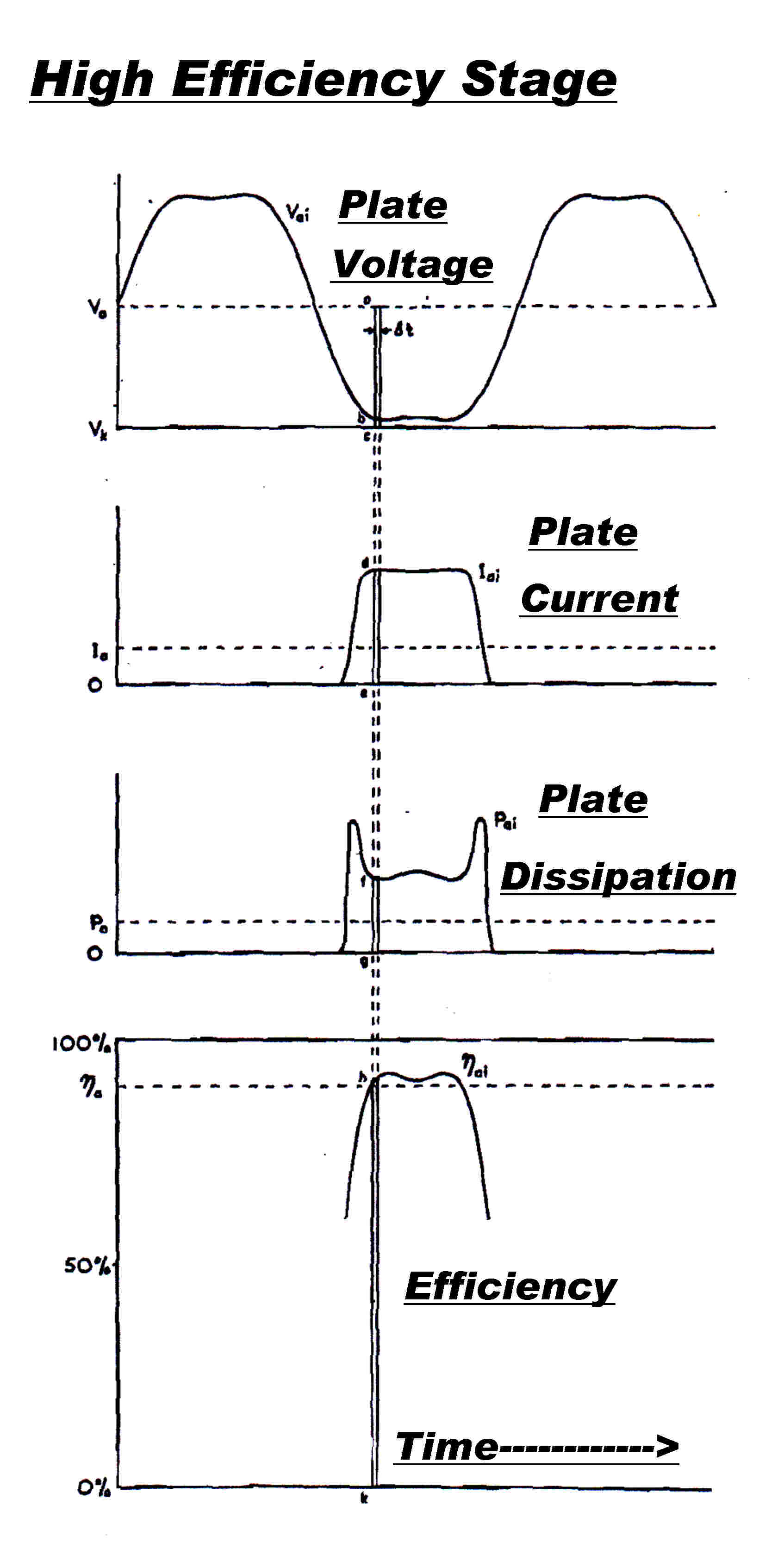

The conventional class C stage is normally run with a (half)
conduction angle of about 60 degrees.
This gives rise to plate voltage and plate current waveforms shown immediately
to the right.
It has been pointed out above that two problems arise:-
[1] A significant fraction of the plate current passes through the tube at a
high plate voltage giving high plate dissiation and relatively low efficiency.
[2] The ratio of peak to average plate current is high, and this is not consistent
with the limitation on filament emission.
The waveforms shown next are are more desirable for :-
[1] An approximation to a square wave in the plate allows plate current conduction
with a much reduced plate voltage, and so lower dissipation and higher efficiency.
[2] The rectangular plate current pulse lowers the peak to average plate current, and so
eases the limitation on filament emission.
FOURIER ANALYSIS - RECTANGULAR PULSE TRAIN - SQUARE WAVE
Fourier Analysis of Rectangular Pulse Train i(t)
Height of current pulse = I
Duty Ratio = k
Repetition frequency = f : angular frequency = ω = 2 π f
x = ω t = 2 π t
Then the Fourier analysis of the pulse train is:-
i(t) = I { k + ( 2/π )[ sin( k π )cos(x) + ( 1/2 )sin( 2 k π ) cos(2x)
+ ( 1/3 )sin( 3 k π ) cos(3x) ........
+ ( 1/n)sin( n k π ) cos(nx) ] }
The magnitude of the components can now be noted:-
Idc = I0 = k I
Ifundamental = I1 = I (2/π)sin( k π )
Isecond harmonic = I2 = I (2/π)sin( 2 k π )
Ithird harmonic = I3 = I (2/π)sin( 3 k π )
For I3 = 0
sin( 3 k π ) = 0
So : k=0 : k = 1/3 : k = 2/3
If k = 0 there is no current - trivial result
If k 1/3 plate conduction angle 120 degrees OK
If k = 2/3 plate conduction angle 240 degrees - not permissible in class C stage
Fourier Analysis of Square Wave v(t)
The Fourier Analysis of a square wave can be obtained from the above equation by
putting k = 1/2 , however it is convenient to write it down directly.
For a square wave of peak amplitude Vpk :-
v(t) = ( 4 / π ) Vpk [ cosx - ( 1/3 )cos3x + ( 1/5)cos5x - ( 1/7 )cos7x
....... ]
A LIMITING CASE - SQUARE WAVE DRIVE AND PLATE VOLTAGE SWING
For an insight into the problem, take the plate voltage and
plate current waveform to the limit - make both a square wave.
For a perfect tube there is no dissipation and the efficiency is 100% -
what is the catch?
For a broadcast transmitter we are interested in power at the carrier
or fundamental frequency only, since this is the only signal radiated.
It turns out that only a fraction of the power in the square wave system
is produced at the fundamental frequency -- and so the scheme fails.
Idc = Ippk / 2
Pin = Idc Vdc = ( 1/2 ) Ippk Vdc
Now evaluate the fundamental component of plate voltage and plate current.
For the plate current pulse k = 0.5 so :-
Ippkf =
[ ( 2/π ) sin( k π )] Ippk
= [ ( 2/π ) sin( π / 2 )] Ippk
= ( 2/π ) Ippk
For tne plate voltage Vppk = Vdc so
Vppkf = ( 4 / π ) Vppk
The power Pf at the fundamental frequency is then :-
Pf = ( 1/2 ) Vppkf Ippkf
= ( 1/2 )( 4 / π ) Vppk ( 2/π )Ippk
= ( 4/π2 ) Vdc Ippk
Pf/Pin = [( 4/π2 ) Vdc Ippk ] /
Vdc ( 1/2 ) Ippk
Pf/Pin = 8/π2 = 0.8106
Only 0.8106 of the power is going into the carrier :: so the scheme fails!
A RECTANGULAR PLATE CURRENT PULSE
We now rely on a basic theorem from linear circuit theory:-
A sinusoidsl voltage can only produce power with a sinusoidsl current
of the same frequency
Suppose we introduce a third harmonic sinusoidsl voltage into the plate to
approximate a square wave.
If we can discover a rectangular plate current pulse with no third harmonic component,
then we have a guarantee that all the generated power will go into the fundamental.
Further, we can alter the magnitude of the third harmonic plate voltage at wil
without affecting the power balance.
From above we had:-
For I3 = 0
sin( 3 k π ) = 0
So : k=0 : k = 1/3 : k = 2/3
If k = 0 there is no current - trivial result
If k 1/3 plate conduction angle 120 degrees OK
If k = 2/3 plate conduction angle 240 degrees - not permissible in class C stage
So: For a rectangular plate current pulse with K = 1/3 - a total conduction angle of
120 degrees - there is no third harmonic plate current and all the power goes
into the fundamental.
Consider a stage with a rectangular plate current pulse and a sinusoidal plate voltage
of variable magnitude K times the DC input voltage V dc
Then:-
vp(t) = Vdc [ 1 - K cos( ωt ) ]
The rectangular plate current pulse has a a magnitude of Ipk and a
duty ratio k
Then Idc = k Ipk
Pin = Idc Vdc = k Ipk Vdc
Pout = 1/2 Vfpk Ifpk
Since Vfpk = K Vdc
Then: Pout = 1/2 K Vdc Ifpk
But: Ifpk = ( 2/π ) sin( 2 k π) Ipk
Then: Pout = 1/2 K Vdc ( 2/π ) sin( 2 k π) Ipk
But the efficiency η is given by:-
η = Pout / Pin
= [ K sin( k π ) Ipk Vdc /
[ k π Ipk Vdc ]
That is η = K sin( k π ) / k π
If k = 1/3 ( 60 deg half angle ) η = 0.827 K
If K =1 η = 0.827 That is: If the plate voltage swings down to zero volts
with a 60 deg. rectangular pulse of plate current K = 1 and the efficiency
η = 0.827
But the efficiency in a normal class C stage with a normal truncated sine pulse
of 60 degrees is 0.897 - higher as expected - so what is the point of the
rectangular pulse ?
We can now add a third harmonic plate voltage without upsetting the
fundamental power delivered to the load.
We now ask: For an efficiency of 1, what plate voltage swing
K Vdv is required ?
K = 1 / η = 1.21
but this would bring the plate negative by ( 1 - 1.21 ) Vdc
= - 0.21 Vdc
Normally this would not be possible, but not here:-
We can add a third harmonic which carries the plate positive and cancels out the
negative swing of the fundamental, so the net plate voltage is positive while
still having a large fundamental plate voltage swing, and so a high and efficient
output.
THIS IS THE BASIC IDEA BEHIND THE TYLER HIGH EFFICIENCY OUTPUT STAGE
We have considered an ideal stage where plate current flows with zero plate voltage.
When allowance is made for adequate minimum positive plate voltage, efficiencies of
up to 95% are possible.
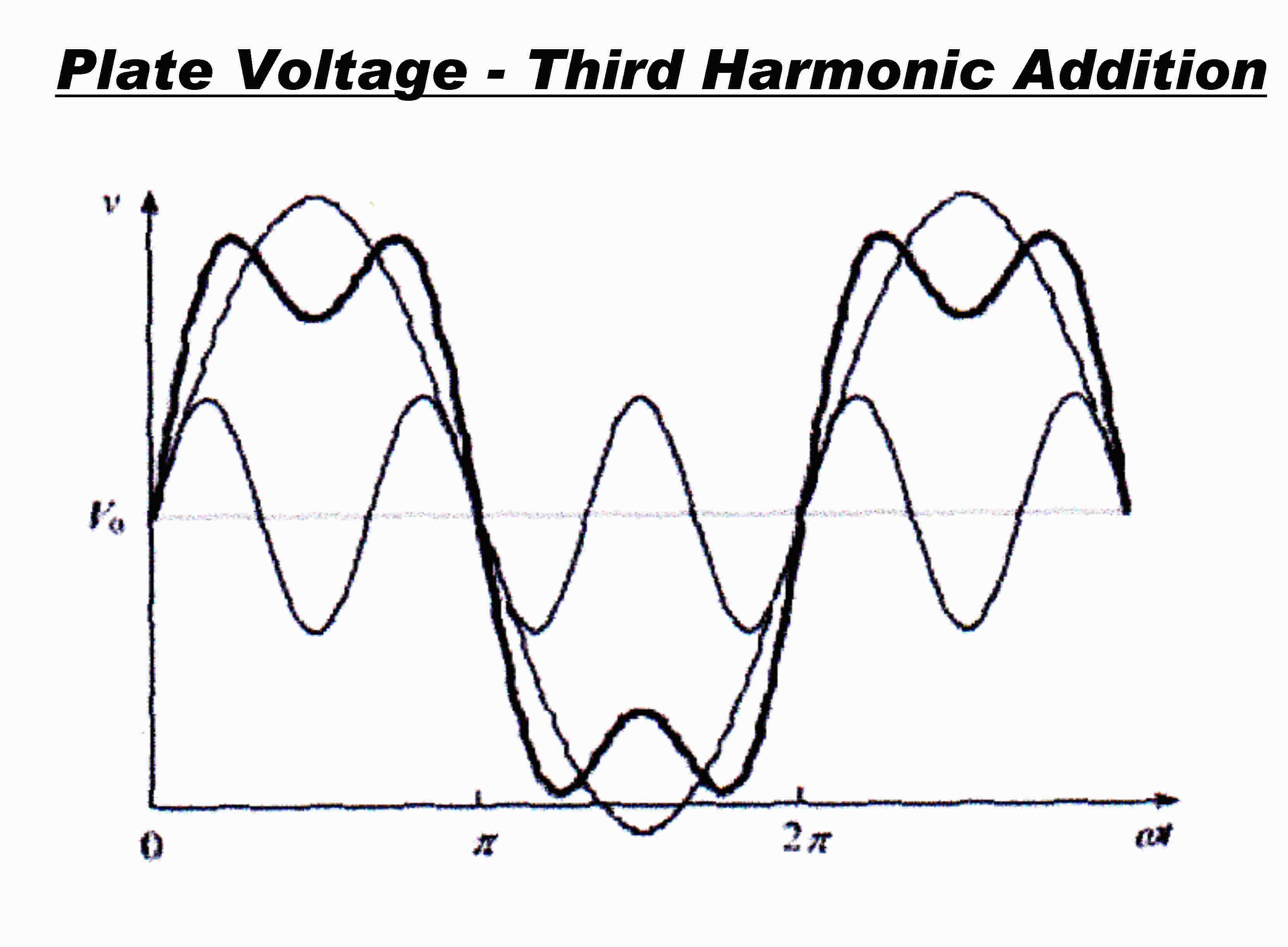 The process described above is illustrated graphically
in the diagram on the right.
The amplitude of the fundamental plate voltage is high enough
to take the plate negative.
The third harmonic maintains a positive plate voltage, allowing the
large fundamental plate voltage swing.
PRACTICAL REALISATION OF THE TYLER OUTPUT STAGE
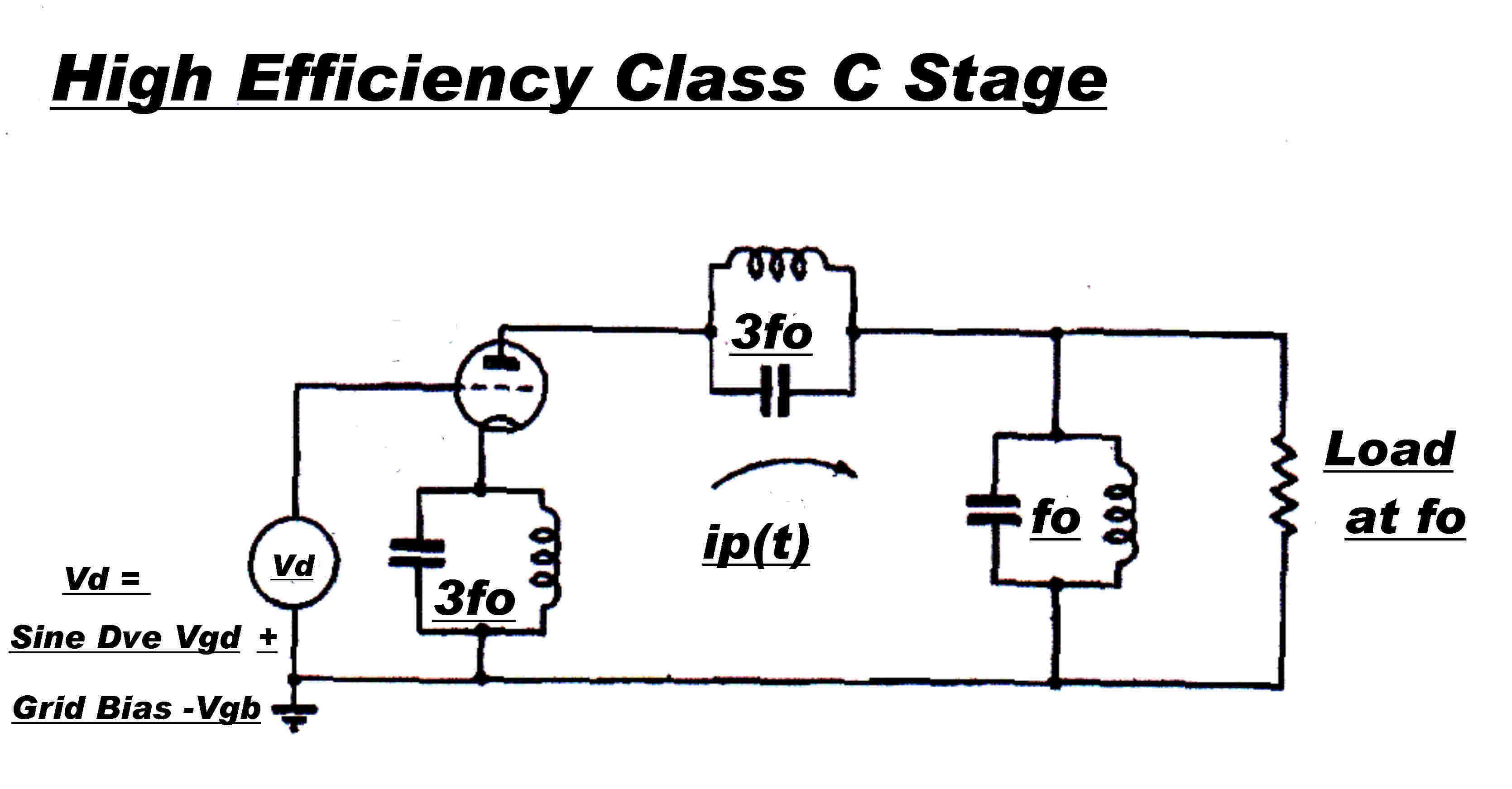 It is desirable that the required waveforms introduced into
the plate and grid be generated by lossless L-C networks.
The usual arrangement is shown opposite.
Plate Voltage Waveform
The third harmonic parallel L-C tuned circuit in the plate is designed with the
highest Q possible, so that it has a very high resistive impedance
at resonance.
It was stated above that the grid drive was designed to produce NO third harmonic
plate current.
In the real world there will always be a small component.
This into the very high impedance of the tuned circuit is enough to produce a
large third harmonic voltage.
The amplitude of this is limited by non-linearities in the plate resistance
of the output tube - so the system is self regulating.
Although the bandwidth of the third harmonic L-C tuned circuit is low, the system
responds to fast changes during plate modulation because of the high gain within
the non-linear feedback loop.
Grid Cathode Voltage Waveform
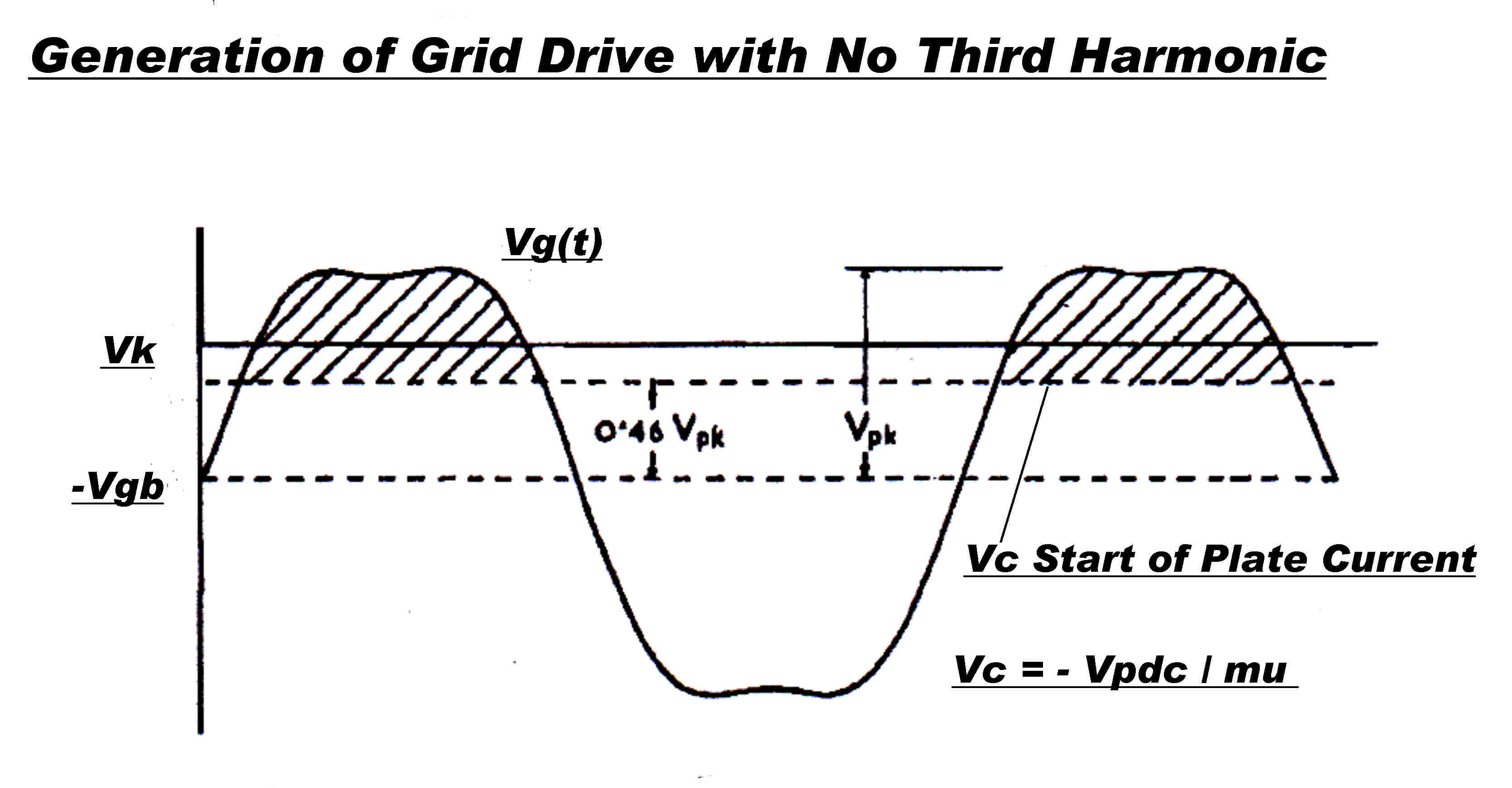 The synthesis of the rectangulsr drive pulse in the grid
presents a conundrum.
Third harmonic voltage is injected between grid and cathode by a
high Q L-C tuned circuit resonant at the third harmonic in the cathode.
The object is to produce a 120 degree rectangular pulse with NO
third harmonic.
How do we achieve this by ADDING third harmonic to the fundamental
sinusoidal grid drive?
The answer: The grid circuit is biased beyond cutoff and non-linear,
and the grid pulse is produced by lopping off the top of the pulse
and drivinhg the grid with that.
The drive pulse is not a good approximation to a rectangular pulse.
Tyler states that it has no third harmonic when:-
[1] 15% third harmonic is added to the grid drive
[2] the grid bias is set to start plate conduction
at 0.46 of the pulse height.
PLATE MODULATION OF THE TYLER HIGH EFFICIENCY RF OUTPUT STAGE
In this region the plate current is a sensitive function of plate voltage,
so the plate voltage waveform accurately tracks the DC input.
The distortion in the plate modulation process is low - an added bonus
to the gain in efficiency.
The develpment of waveforms for a high eficiency RF output stage
is neatly summarised in the operating manual for an AWA broadcast transmitter.
It is an excellent example of the final development of the
classical plate modulated transmitter.
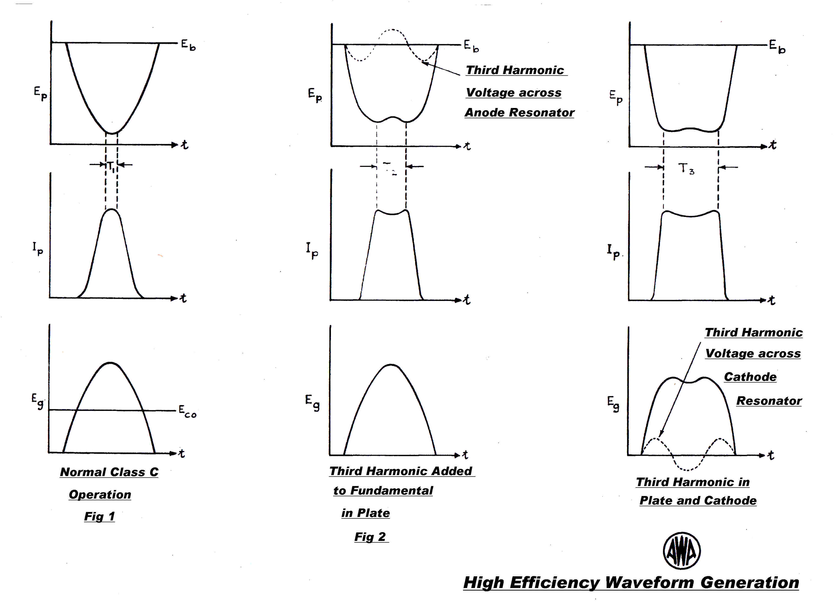
This 50KW STC high efficiency plate modulated transmitter carried
the popular or "light" program of the ABC and provided excellent service over
a wide area.
The compressor amplifier was particularly active about forty years ago
when the following audio was recorded from this transmitter.
The level of the surface noise and turntable rumble from the 1926 disc
rises as the signal level falls - particularly at the end.
At any rate, a 1926 disc cut with the Harrison cutter modulating a large
all vacuum tube transmitter is a very satisfying experience.
Historic 4QR Audio
As pointed out above, the performance of the plate modulated
transmitter exceeded the capabilities of most receivers while still
offering high efficiency.
There was no incentive on the designers to upgrade the performance.
There were a very small number with ultra low distortion tuners who could
appreciate an improvement - say from 2% to 0.2% overall total harmonic
distortion.
Such am improvement could only be obtained by overall envelope feedback.
Winding capacity and leakage inductance degraded the modulation transformer
response to such an extent that any significnt overall feedback became impossible.
It is stil possible to bypass the modulation transformer and choke to allow
a significant amount of feedback.
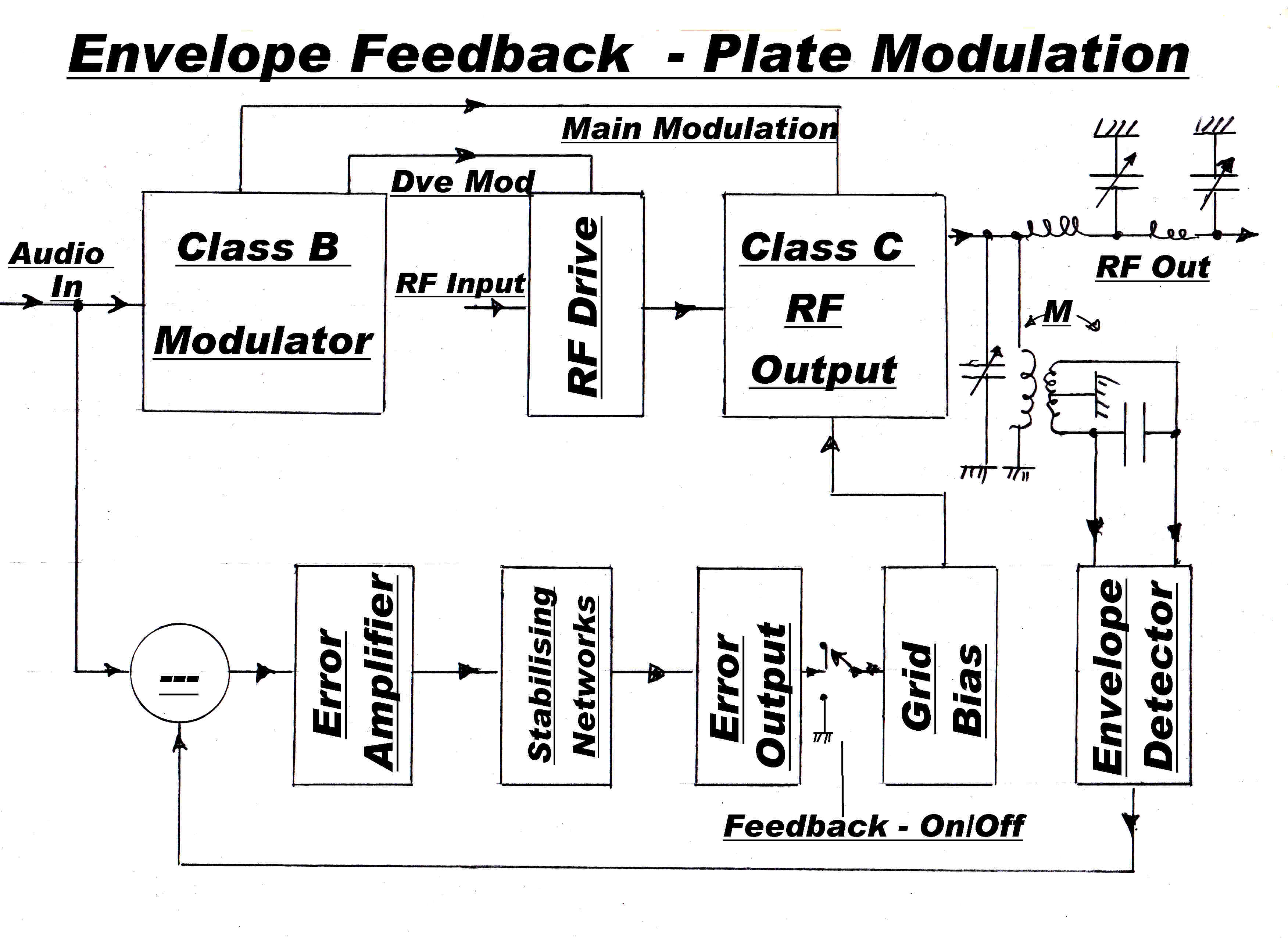 "If you can't go through it, go around it !" applies
to feedback loops too.
Many feedback problems can be solved with parallel loops.
One of several solutions to the problem of feedback over plate
modulation transmitters is shown opposite.
The error between the incoming audio and transmitted RF envelope is amplified
and applied as grid modulation to the final stage.
This has the following advantages:-
[1] It bypasses the modulation transformer and choke.
The feedback transfer function is now limited by the
bandwidth of the tank circuit in the RF amplifier plate.
[2] It operates at a low level, since the total correction is only a
few per cent.
[3] It can easily be switched out of circuit and the transmitter
operated without feedback.
The WLW Rockwell transmitter achieved a distortion figure below 0.2%
with some rather "touchy" circuitry.
The same can be done with a much simpler parallel feedback loop.
Alas the great days of vacuum tube transmitters have passed, and we will
never see the idea realised in a high power transmitter!