AMPLITUDE MODULATION HIGH FIDELITY
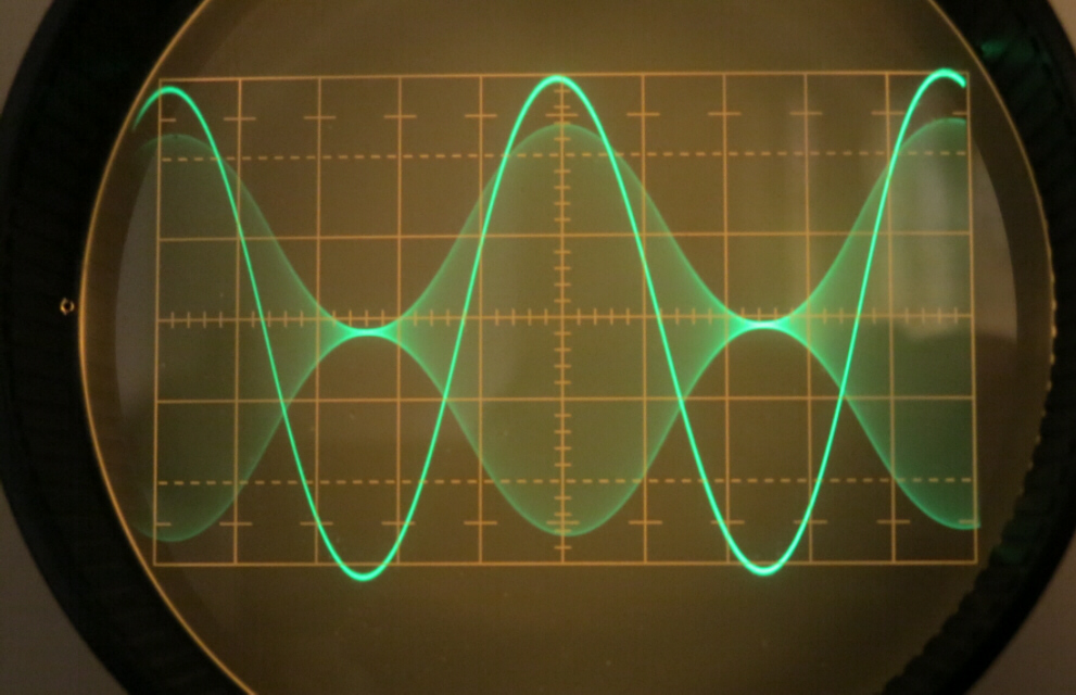
AMPLITUDE MODULATION HIGH FIDELITY

This site was started to promote AM transmission on the Broadcast Band.
It has been extended to cover other interests - vacuum tube design and
early recording equipment.
CONTACT : COMMENTS AND QUESTIONS
AMPLITUDE MODULATION
[1] The properties of both AM and FM are developed both intuitively and mathematically
in the introduction.
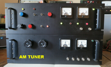
[2] The design of a solid state AM tuner with a maximum bandwidth of about 38KHz. and
neglgible distortion is described in detail.
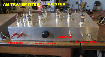
[3] The design for a low power AM transmitter for the broadcast band ( 500KHz to 1500KHz )
is given.
Techniques for reducing the distortion to a very low value are analysed.
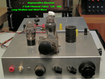
[4] A regenerative receiver employing 2 volt filament tubes rounds out the section
on AM receivers.
A sample of audio from both receivers is included.
[5] The design of a complete vacuum tube audio system is described.
This comprises:-
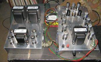
[A] A power amplifier with eight 6V6s in parallel push-pull.
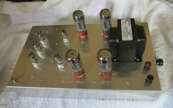
[B] A power amplifier with four 6L6s in parallel push-pull.
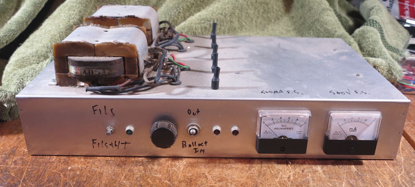
[C] A variable voltage ( 250V - 320V) regulated power supply with current limiting suitable for
setup and debugging of vacuum tube equipment.
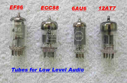
[D] A low noise preamplifier switchable for stereo , mono lateral and mono vertical recording.
[E] A universal disc equaliser to handle all acoustic and electrically recorded discs.
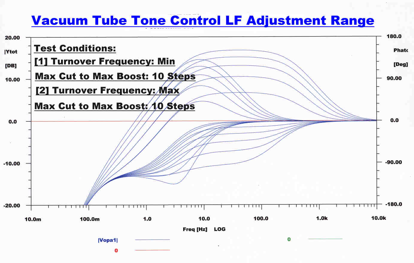
[F] A universal tone control with variable amount of treble and bass cut and boost and variable
turnover frequency.
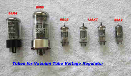
[G] A high performance voltage regulator for the low level stages.
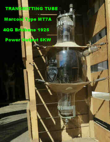
[6] A short history of the Brisbane national vacuum tube AM transmitters 4QG and 4QR
is given along with design details.
Sample audio from these transmitters is included.
The first Brisbane FM transmitter in 1953 is also covered.
[7] A rigorous algebraic and numerical analysis of circuits encountered in Ampliphase
transmitters is presented.
It is hoped that this may stimulate discussion.
The site is under construction with sections on actual and model Ampliphase
transmitters to be added.
DESIGN of VACUUM TUBE EQUIPMENT
The design of vacuum tube equipment is rapidly becoming a lost art.
The detailed design of the following vacuum tube equipment is included:-
[1] A push-pull 6V6 audio amplifier
[2] A push-pull 6L6 audio amplifier
[3] A high performance low power AM transmitter
[4] A two tube regenerative receiver with audio samples
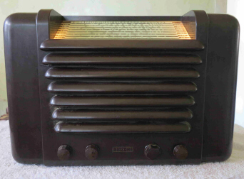
[5] An Australian radio receiver from the forties
[6] A high performance Voltage Regulator
[7] A Vacuum Tube Preamplifier and Disc Equaliser
[8] A Vacuum Tube Universal Tone Control
[9] A History of the Brisbane Vacuum Tube Broadcast Transmitters
AM 1925 to 1990
FM 1953
The Interaction between Transmitter and Receiver Design
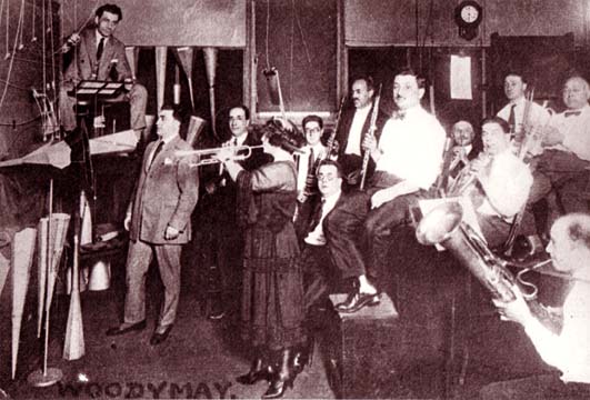
ACOUSTIC and EARLY ELECTRICAL RECORDERS
The detailed design of the following equipment is discussed:-
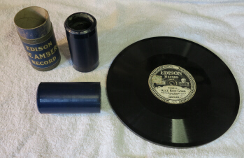
[1] Edison Vertical [ Hilland Dale ] Recorders
[1A] Audio tracks are included to illustrate the above
[2] Vertical Recorders with Negative Feedback
[2A] Audio tracks are included to illustrate the above
[3] Henry Harrison's 1926 Recorder
[3A] Audio tracks are included to illustrate the above
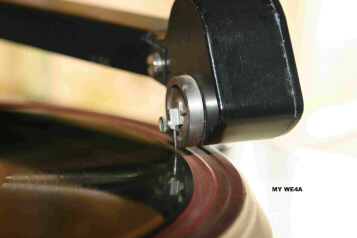
[4] The WE4A Reproducer
[4A] Audio tracks are included to illustrate the above
[5] Early Australian Pickups - The CE and MBH
[6] Eighty Minute Concerts from Edison Hill and Dale Diamond Discs
The Discs are chosen at random. Most are acoustically recorded
with some electricals included.
 |
|
 |
|
 |
|
 |
|
 |
|
 |
|
|
A 250 -320 VOLT BUFFERED AND CURRENT LIMITED POWER SUPPLY FOR VACUUM TUBE EQUIPMENT TESTS |
 |
 |
|
 |
|
 |
|
 |
|
 |
|
 |
|
 |
|
 |
|
 |
 |